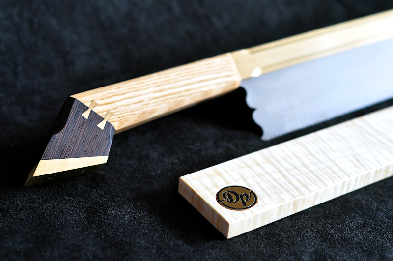
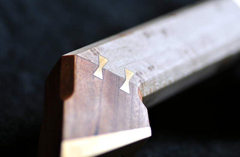
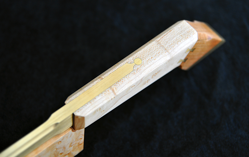
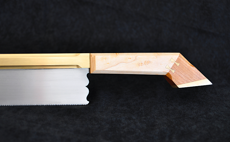
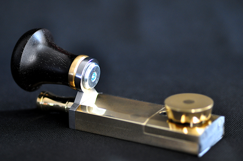
Making a brass infill plane (Hattori Hanzo, DP)

UKworkshop.co.uk

Help Support UKworkshop.co.uk:

This site may earn a commission from merchant affiliate links, including eBay, Amazon, and others.
Another small update.

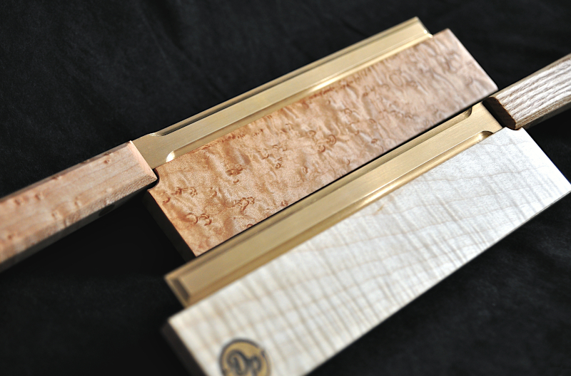
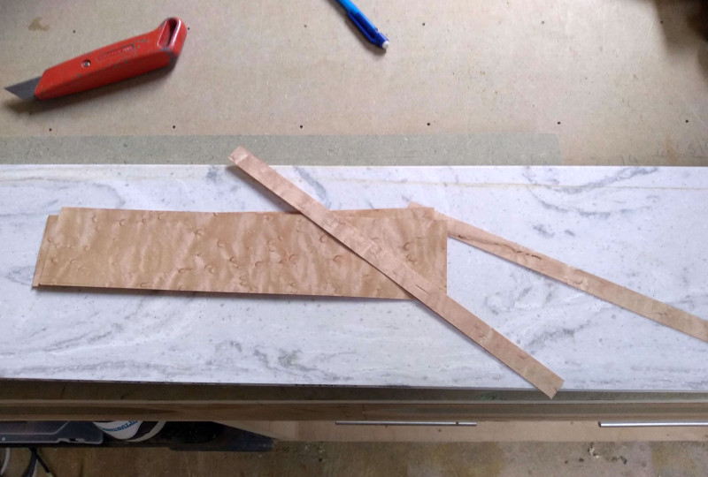
Now the sheath cases are dry and cleaned up I started to work on the veneers.

I cut Thin strips for the edges of the sheath and larger pieces for the front and back.
3yz8NRd.jpg


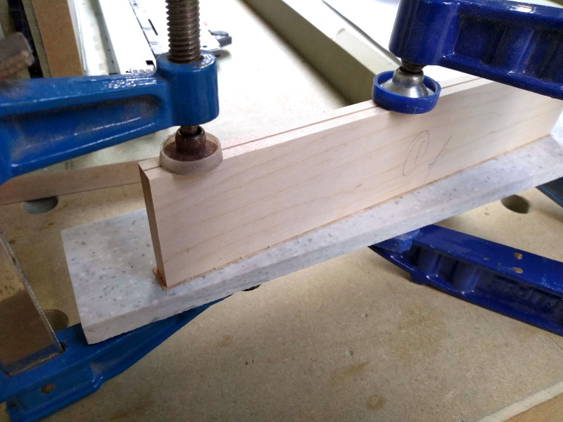
I carefully spread pva glue onto the edge veneers and used a flat surface to cramp against to ensure the veneers laid flat.
Careful application avoids unnecessary glue squeeze out.
KnUG5Dd.jpg


I repeated the same process for the ends of the sheath.
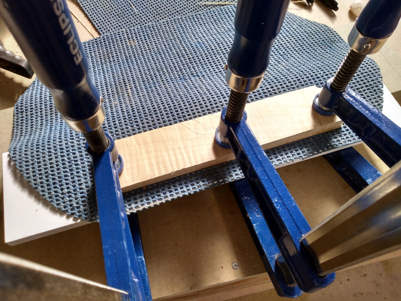
Once the glue had dried I planed any over hanging veneer flush with the sheaths surface and proceeded to glue the front and back veneers in place one at a time.

I use a piece of foam matting to ensure even pressure on the veneer and to compensate for any inconsistencies in flatness on the sheath body.
Vz8dtOj.jpg


I repeated the process for the figured sycamore veneers but in my haste I had forgotten I needed to cut a relief in the back of the sheaths so the saw blade can be fully inserted.

Annoyed!

I cut and filed the relief notch then soaked some strips of veneer in boiling water before wrapping them round a similar sized piece of dowel.
Soaking and pre-shaping the veneer is critical as it would likely crack/split if applied dry.
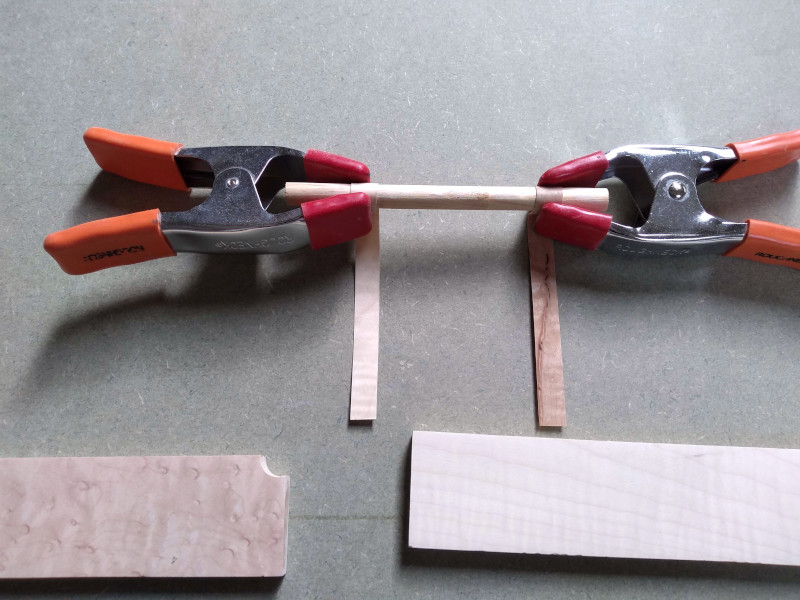
dQDRTvN.jpg


Once the veneer was slightly dryer I glued it in place.
Not the end of the world but ideally I'd liked to have had all edges glued in place before the front and back veneers are applied, this hides any joins on the face of the piece being veneered.
I'm hoping I should be able to blend these small bits in when I come to sand up the sheaths.
 
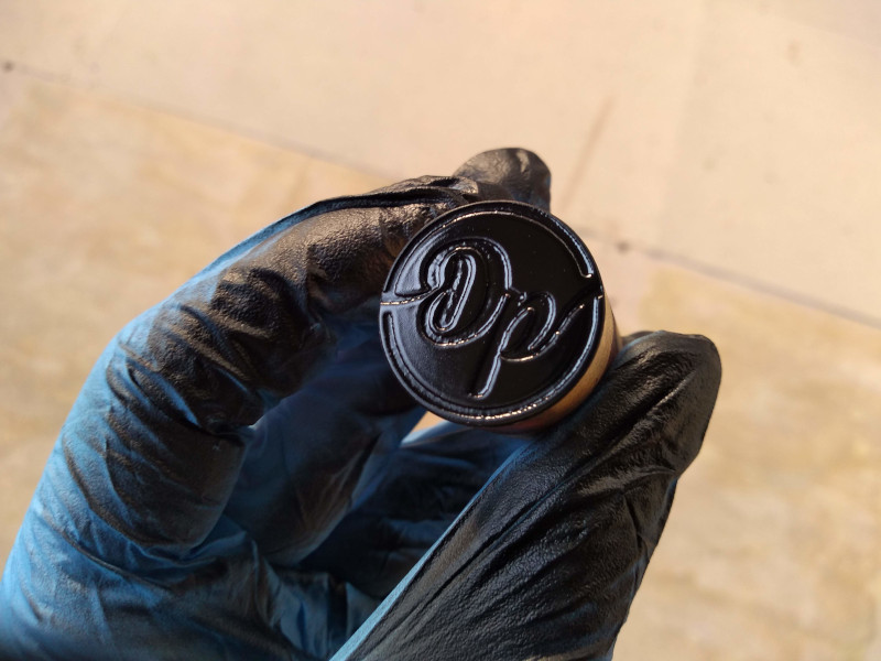
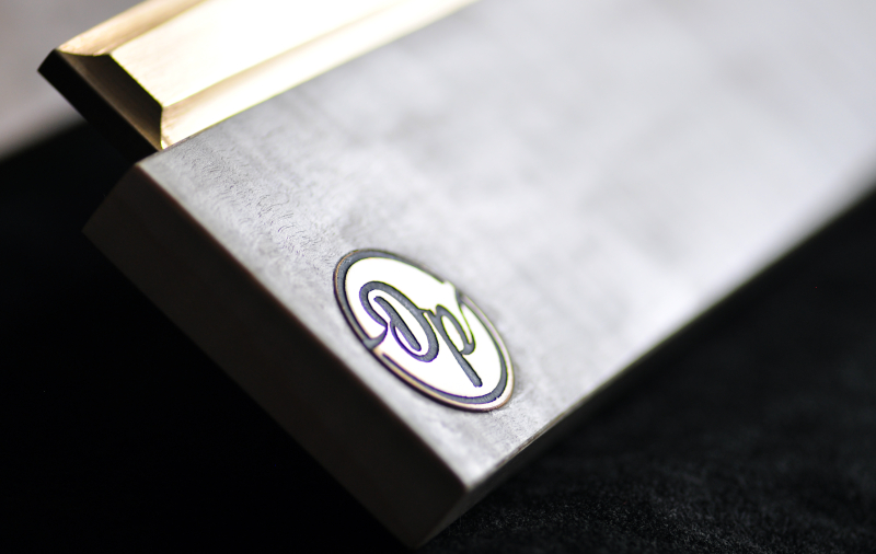
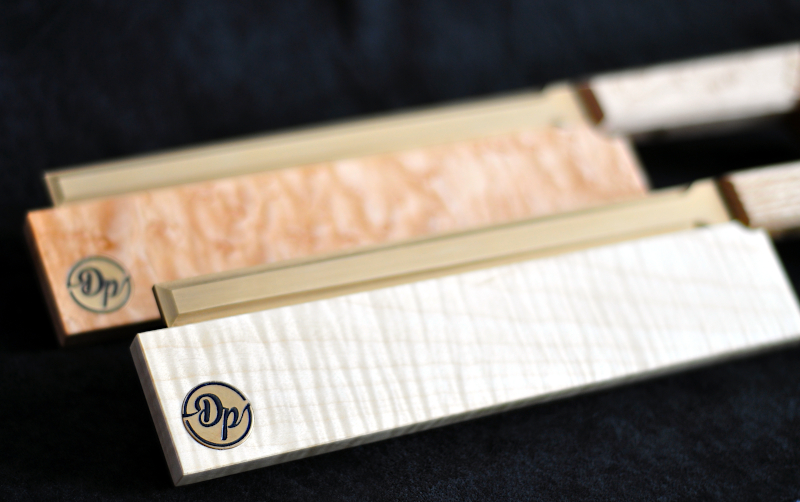
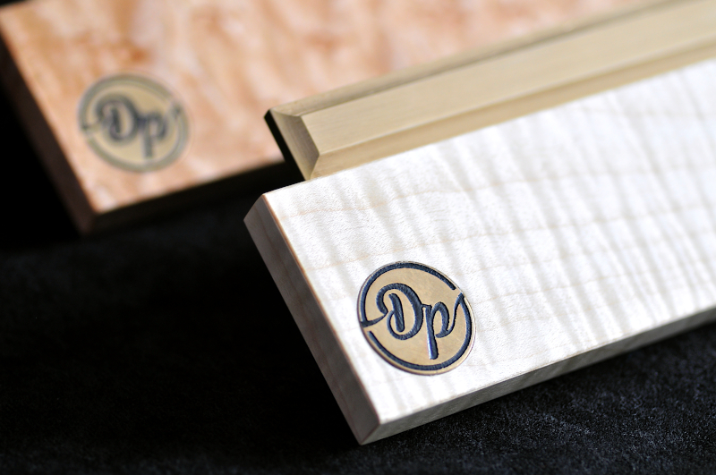
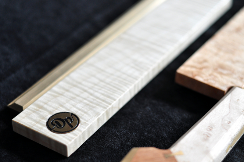
With the sheaths veneered the final touch was to add my initial mark.

I had a few vinyl stencils left over from the last plane build which luckily where a perfect fit on a small piece of brass round bar I also had left over.
I'm currently working on a new name stamp so hopefully I'll get that sorted for the next project.

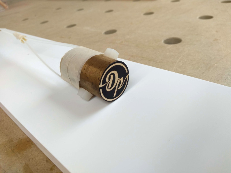
I carefully squared off the brass round bar then degreased it with rubbing alcohol and fitted the stencil.

dGU47Yh.jpg


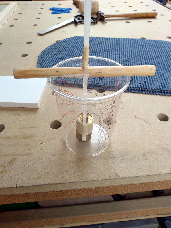
I secured cable ties to the brass with masking tape and used a piece of dowel to suspend the brass in a measuring cup.

AefoSDC.jpg


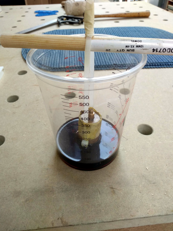
I then filled the cup with ferric chloride to slightly above the stencil. The reason I suspended the brass with the stencil facing down is so that as the acid etches into the brass the waste material will fall away rather than clogging up the stencil, this should hopefully result in a better etch.

mwHXpho.jpg


zkm4f3A.jpg


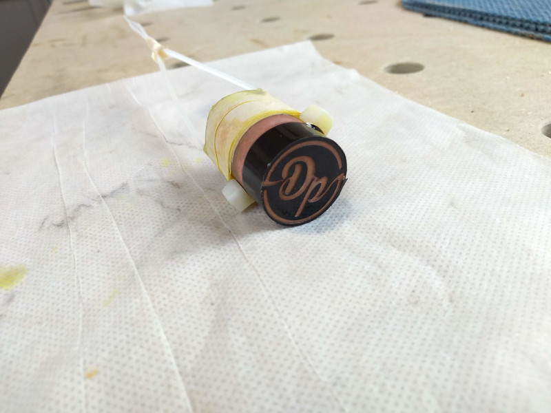
I left the brass to etch for around an hour after which I removed it from the acid then used baking powder to naturalize any remaining acid and rinsed away the surplus with cold water.
Thankfully the vinyl stencil remained intact and was unaffected by the acid, I'm really pleased with how the etch turned out.

5wQ7vWM.jpg


I then left the brass to fully dry before giving it a coat of black paint, again leaving that to dry then sanding off the face to leave the etch blackened.

AoTFRJj.jpg


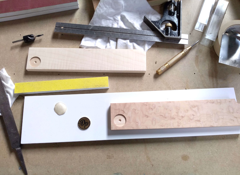
I needed to cut the mark from the bar and flatten it to a uniform thickness. I used a hacksaw and did my best to cut a straight line. I then drilled a tight fitting hole into a piece of MDF to the required depth and used the linisher to sand the mark down. I rotated the MDF every few seconds to ensure I was flattening the brass evenly. As soon as the MDF was touched I stopped and removed the mark.

D0r0b2D.jpg


One down, I then repeated the whole process for the other mark.

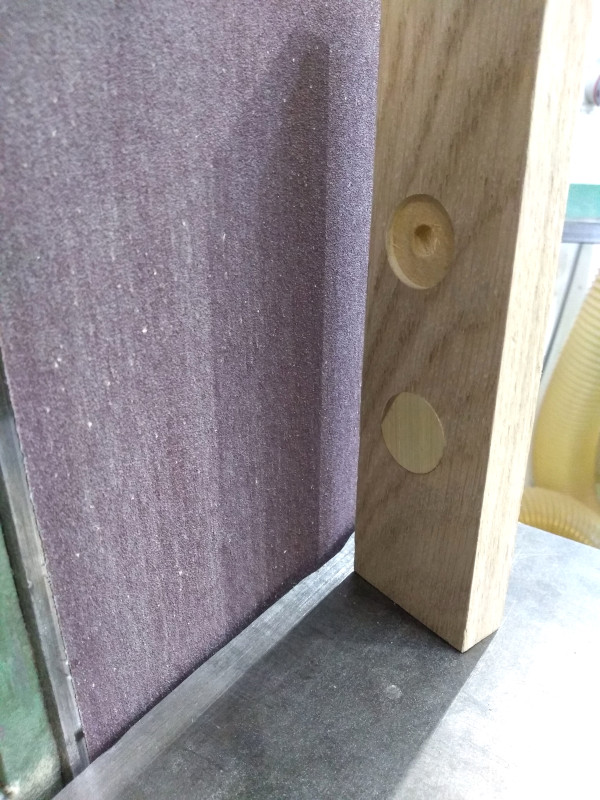
I then carefully marked out and drilled both sheaths with a tight fitting hole to the same depth as the mark.

n5T0r9p.jpg


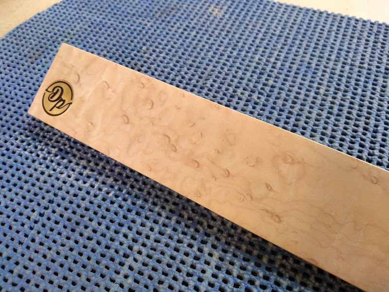
And finally fixed the mark in place with a little epoxy and a G-cramp with a buffer to protect the mark from scratches.
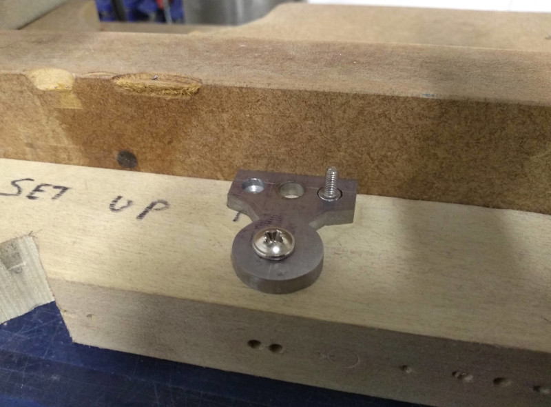
92yzbc7.jpg


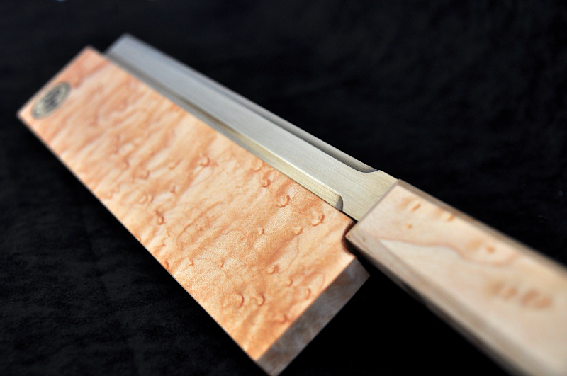
I had this design in my head from the beginning of the project and I'm pleased with how the sheaths have come out. Originally I had planned to have my mark slightly smaller but the lack of a lathe now means I have to go with the materials I've got.
I've been looking into mini bench top lathes which would be perfect for my needs but even the dubious Chinese ones which require a lot of fettling are quite expensive, second hand branded lathes seem to be holding there value extremely well to, most of which go for well over my budget :(
 
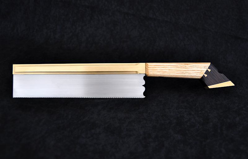
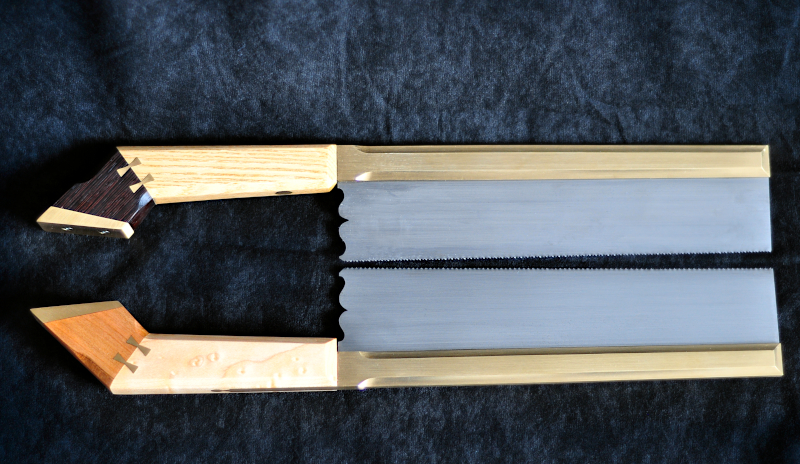
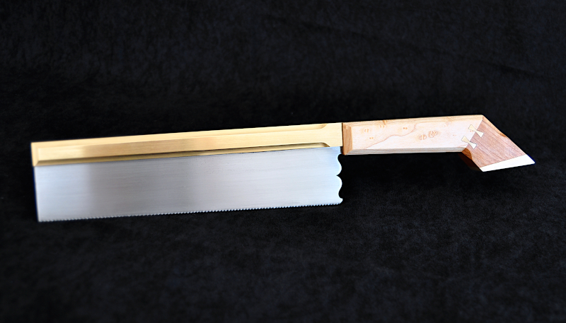
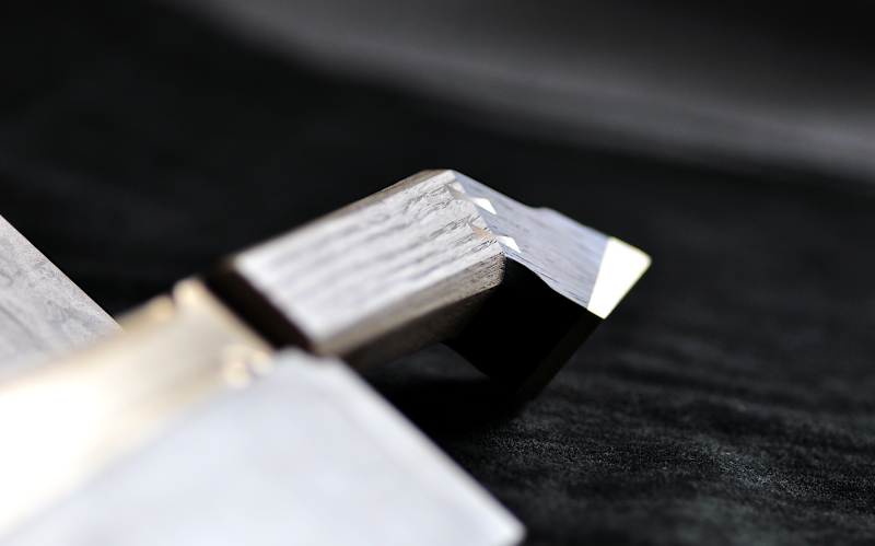
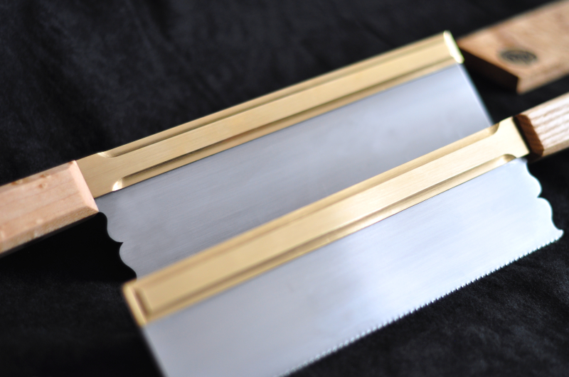
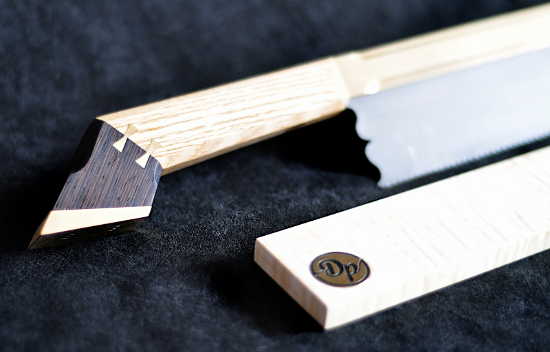
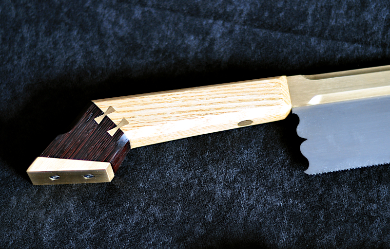
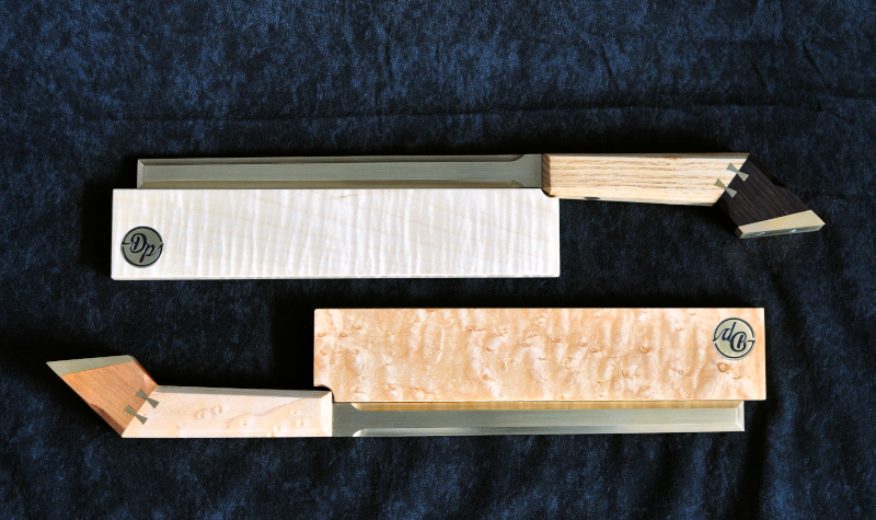
Finally after a lot of sanding and waxing the saws are finished.

I took the handles up to 320 grit and the sheaths to 500 then finished them with a few coats of diluted linseed oil and buffed them to a nice sheen with neutral bison wax.

I'm really pleased with how they have turned out. They have stayed true to the vision I had in my mind with only a few minor changes along the way.
While initially they feel a little strange to hold (the solid brass backs add a considerable weight over a folded back and the angular handle while not uncomfortable takes a bit of getting used to, though I quickly learn to hold the saw in the same way every time I pick it up unlike a rounded handle gents saw which can take a few repositions to feel right) after a little use they start to feel more familiar to my hand.

I've not had the chance to use them a great deal as of yet but I'm looking forward to giving them a good work out to see how they shape up.
The 16tpi blade seems to be performing very well but I want to get hold of a decent needle file to dress up the 22tpi blade as I feel even my double extra slim saw file is a little to large, I'm curious to see the difference it could make.

Lots of pics incoming!

01
lEBfzsh.jpg


02
Vefh7UN.jpg


03
7b6Ubdb.jpg


04
wqCjd3w.jpg


05
ItKchiw.jpg


06
228JqPM.jpg


07
2EUgtpS.jpg


08
nt5L8EB.jpg


09
SddO7Nw.jpg


10
k2f8uqG.jpg


11
o3Otdiu.jpg


12
L3GdYbJ.jpg


13
p473OLx.jpg


14
Naa9kr9.jpg


15
Gt6TRYQ.jpg


16
oimSnSS.jpg


17
xjCOv7r.jpg


18
RLNbmtF.jpg


19
ZcW9dWr.jpg


20
3aKHgpR.jpg


I didn't manage to capture much video of the build unfortunately, I actually started this project this time last year but had to put it on hold for reasons I've mentioned earlier. I'm very fortunate to be able to carry on doing something I really enjoy especially with the way things are at the moment.

I have put a video together of the footage I did get if any one is interested.


Cheers
Dan.
 
All spectacular and very inspiring, can I ask (I can’t see that you have said), how you worked out / obtained the dimensions for your planes ?
An insight into your planning, set out and drafting skills would be very enlightening.
 
Last edited:
Thanks for the comment bodger.
To be honest most of it is just in my head. I look at pictures or watch videos and guesstimate the rough sizes.
I haven't followed any true plane sizes as such, I do a quick sketch or visualize it in my mind at the start then go from there. I sometimes adjust proportions as I progress though the build to what I think looks and feels right but mostly I just follow what I've imagined.

A lot also depends on the material sizes I have available at the time, sometimes I have to adjust dimensions to what I've got.

The saws where made totally from memory but for the planes I did a very crude drawing on paper or mdf, my drawing skills are truly awful!
If I come up with an idea in my mind I usually sketch it out on a piece of paper but I think it would be nonsense to any one else looking at it.

This is the drawing I did for the first plane I made and the blade adjuster, again most of it was in my head. I also made a few wooden mock up lever caps and handles which you can see around the drawing.

amkKlQk.jpg


This was the first mitre plane. The sizes where just what I thought looked right at the time.

sXlVd3U.jpg


This was the second mitre plane. Wasn't much to go on.

ZmwmlFW.jpg


I think because my drawings are so bad and I don't enjoy the process all that much I've learnt to picture things in my mind and go from there.
Other than a few sketches to jog my memory along the way that's normally the way I work.

I think its obvious I much prefer the making stage over the planning :)
 
I don't see anything unusual in your approach, HH, mine has much in common. I think my working sketches are rougher than yours, but "working with the material I happen to have in hand" sounds very familiar! 😀

With planes, there are a few design details to be observed, like using a suitable proportion of toe to heel, depending on its intended use, but otherwise it's a pretty clean slate. Sizes are matters of personal taste, different people choose different sizes of plane to do the same job. The size of some scraps I wanted to find a use for determined the sizes of some finger & thumb planes I made. They were done for fun & to see how small a body I could dovetail up, but they turned out to be far more useful than I expected, which was a bonus.

The "give it a go & see" approach has led to a couple of serendipitous successes and a couple of spectacular failures, but it's all good experience. In fact failure can often teach you far more than instant 'success' . If the thing works reasonably well, one tends to accept that gratefully & just get on & use it, whereas a failure usually gets investigated & analysed & valuable lessons may be learnt.

There are two aspects of those continuous-side mitre planes that are worrying to someone like me who is still hovering on the verge of tackling one, & these may be what old.bodger was alluding to. One is how you figure out what diameter bending form to use to get the right body width. Springback is going to make life difficult if you use the same diameter form as the finished bend, and what also bothers me is that the amount of springback is so variable, with harder alloys having far more than softer alloys. Having bent up sides for a dozen coffin-shaped planes of all sizes, I've come to the conclusion that figuring out how much extra curve to put on the bending forms is more art than science!

The other worry I have is setting out the holes for the bridge & cutting them before bending. If the bend goes just a little astray, the two sides will not match & you could have an obviously wonky bridge, which would rather spoil things. So I'm torn between fitting the bridge in the traditional way, or fitting it after the chassis is peened up. I watched Bill Carter's videos on making mitre planes very carefully, he talks about this & the need to be especially careful, & tosses off a remark at one point that if the holes do end up out of alignment "there are ways to deal with it", but doesn't elaborate further, or if he did, I must've missed that bit.

I'd love to be able to spend a day or three lurkng in the shed of the old master, just watching him work & picking up a few extra clues...... ;)

Cheers,
Ian
 
Totally agree with your comment Ian, it's brilliant when things go well first time but you learn so much more when things go a bit astray and you have to work out a solution to an unexpected problem.

For the bend radius, I decided how wide I wanted my plane to be (or rather what size blade I wanted) then made a former from a piece of hard timber, the harder the better, the radius being half the plane width.

uZP5zcl.jpg


I didn't find spring back to much of an issue, like you say there is no real way of countering it efficiently as it will be different for every piece of metal.

As long as the front dovetails are tight fitting they will hold the body in place, then any bow left in the body can be taken out when peening the bridge in place.

What's more important to consider with spring back is material thickness.

My first mitre plane body was made from 6.4mm brass and it took a lot of effort to bend it (using a 3 foot pole and sash cramps)
As you can guess the spring back from it was huge but like I mentioned once the front of the plane was put in place it held it fine, I had to squeezed it together with g-cramps so it was fitting tightly to the wooden former in order to get the front on.

My second mitre plane body was made from 3mm brass and was easy to bend and pretty much held it's shape after being bent with minimal spring back.

I think 3mm is about the right thickness for a mitre plane body, I certainly wont be making another one from 6mm any time soon, though it is a lovely plane to use :)

For the bridge on the first plane I cut the hole to full size before bending which I think is fine to do but if I where to do it this way again I would make the hole a lot smaller than needed so I had more room for correction if the holes didn't align after the body was bent, this way you can get the bridge spot on.
The bridge on this plane is slightly out, not enough to notice by eye but when inserting the wedge for the first time it became apparent, though it's easily overcome by adjusting the wedge to suit.

As long as you are very accurate with you're making out on both the body and the wooden former it should all line up fine.

OusVtDa.jpg

Here you can see the centre of the plane is lined up with the centre of the former, as long as it doesn't move while being bent and the bridge holes are marked out and cut accurately it should come out fairly well.

If the bridge holes are not aligned this will also mean the bed of the front dovetails won't be parallel either which would leave you with a skewed plane.
You can try to correct this by clamping one side of the plane in the vice and tapping the other side in the opposite direction to align the bridge holes and front dovetails.

If the holes are only a little bit out it should be fairly easy to correct, if they are a long way out you run the risk of deforming the radius at the back of the plane.

I explain it a little at the start of this video.


For my second plane I didn't use a bridge and instead used a rod to hold the lever cap.
This makes things a little easier as you can drill the hole after the plane is assembled and peened together but great care still has to be taken to ensure the hole is being drilled square and straight.
Care also needs to be taken when peening the rod in place as it is very easy to over do it and bow the sides of the plane inwards. this is a benefit of having a bridge in that you have a shoulder to peen up to.

Another important consideration is the spacing of the first dovetails at the bent end of the plane. If they are put to closely to the bend they will be partially curved. It's not the end of the world if they do as I actually think it looks nice with the dovetails going round the bend but it obviously makes it a lot harder to fit and peen them to the sole.

Hope this rambling make some sort of sense, I'm not great at explaining things.
 
Last edited:
Thanks for the encouragement, HH. Yep, it all makes sense to me, I guess I have enough experience to recognise what you are describing. It's funny, in a way, you started out with the most difficult body to assemble (at least I think so!), and used way heavier side material than I would have chosen (adding considerably to the difficulties!), but pulled it off remarkably well. Sometimes it pays not to over-think things & just get stuck in. I reckon you'll find a small smoother or similar a doddle after your mitre plane experiences.

I was ambitious enough with my first build, choosing curved sides with little idea when I started of how I was going to make the curves. That plane had a very prolonged gestation, and almost went to landfill on a couple of occasions, but after many stops & starts it finally got there. I've probably done 7 or 8 curved side planes of various sizes now, and got the process down pretty well, so I don't know why I'm still fussing about the mitre plane. I got as far as marking out the sides & making a blade for it, but they've been sitting there silently nagging me to get on with it, for several months!

Of course, the way to avoid any bridge problem would be to fit a lever cap, like on the later "improved" mitre planes. I've made plenty of lever caps now, & fitting those is easy, particularly with parallel sides. I could also fit the bridge later, using screws or pins like I did on my little thumb plane, but I do want to try fitting a traditional bridge with through-tenons.

I just need to stop being a wimp, get the digit extracted & get on with it!
Cheers,
Ian
 
January has rolled around again and for most of us It couldn't have come soon enough.

Hopefully 2021 will be a brighter, happier year…..After this lock down......we'll see!


You may remember a jig/idea I had mentioned when making my gents saws to aid in the filing of the saw teeth.

Well, finally I've had the time to work on this project and have eventually managed to get it finished.


I started making those saws and hand filing the plates back in Dec 2019, the first jig I made to cut the teeth was pretty simple but it worked so well, far better than I ever imagined it would, so much so that I wanted to develop the jig further.

After a lot of deliberation I finally settled on a design and set about making it, but before that I did some searching on-line to see if there was anything similar already out there. I couldn't find anything quite like it, perhaps for good reason, it maybe totally unnecessary but I've found it works really well for me and I really enjoyed making it, so why not.


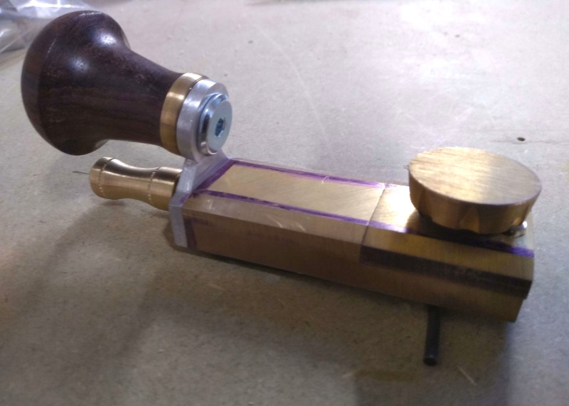
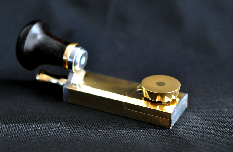
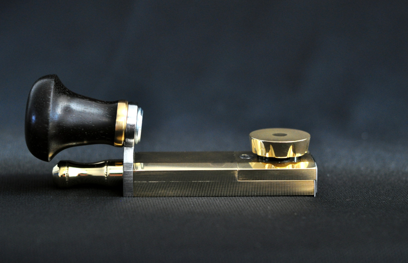
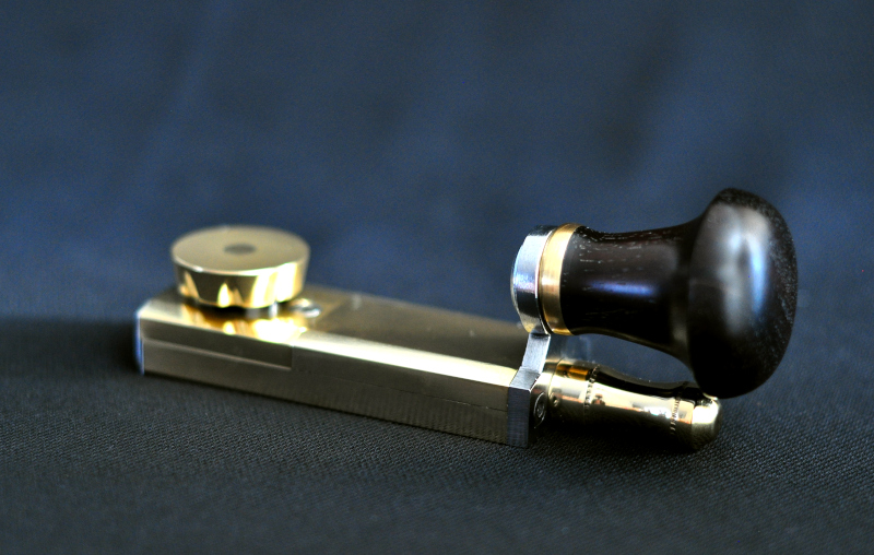
I'm calling it a "handsaw re-toothing guide" and is used with a hacksaw to accurately cut notches into a saw plate, these notches can then be used to locate a saw file to begin shaping the teeth. I’m aware this isn't a new idea but does have some benefits over cutting the teeth with a file alone.

For someone like me who only re-tooths saws occasionally it's made the process much easier with consistent results. I have used it on 4 saws now and they have all come out great.
It’s mainly intended for smaller handsaws in the 24 to 12 tpi range, though it could possibly be used for small panel/rip saws as well.


I didn't get any video of the build process but did take a lot of pictures along the way which I'll go through first, I've also made a video of the guide in use which I'll post at the end.


I'd be really interested in your thoughts on the guide.
I managed to get some video on the first version of the guide which if there were any interest I could post if people wanted to make their own.


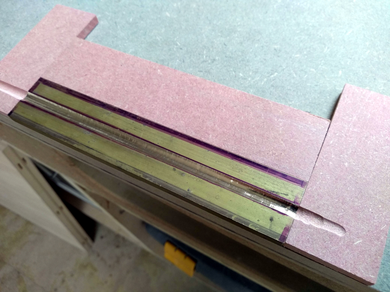
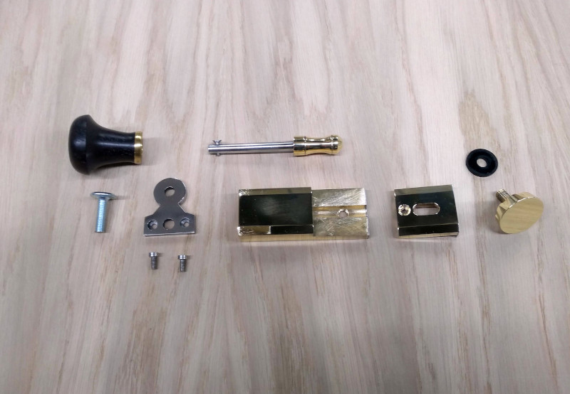
I started with a piece of brass flat bar. I ran a shallow groove in the centre of the bar using a router.

The bar will later be cut in half and fixed back together, I cut this groove in the hope it would act like a pilot hole, as I needed to drill a straight hole through the brass and feared the drill bit would wander when drilling on the pillar drill.


dNIhob3.jpg


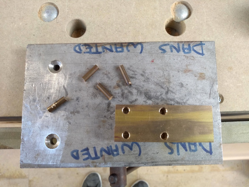
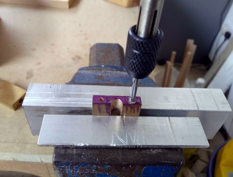
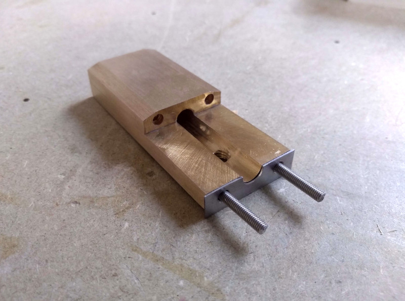
Here I have cut the bar and drilled holes ready for some brass rod to be inserted and peened to permanently fix the halves together.

QlvyD0j.jpg


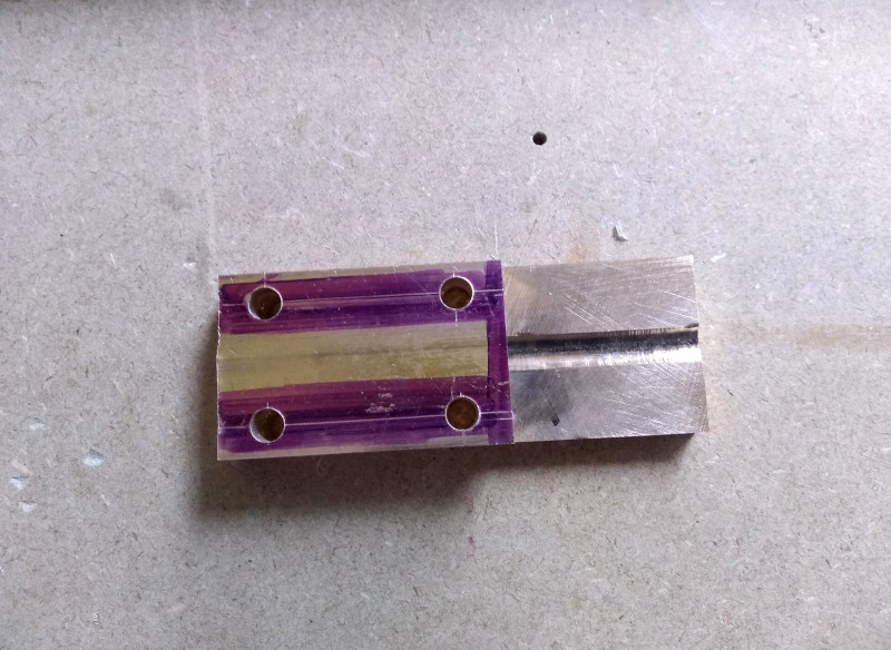
I cut the brass rod to length and add a small countersink to the holes so the brass can mushroom into it when peening.

Jz6ZgHf.jpg


Next I remove the surplus peened brass and drill the centre hole through the middle of the block. The groove I cut at the beginning worked as intended though in hindsight I needn't have cut it so deep.

JZ49zMn.jpg


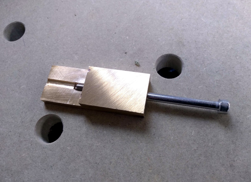
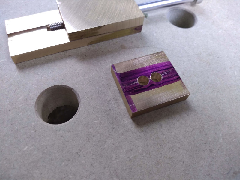
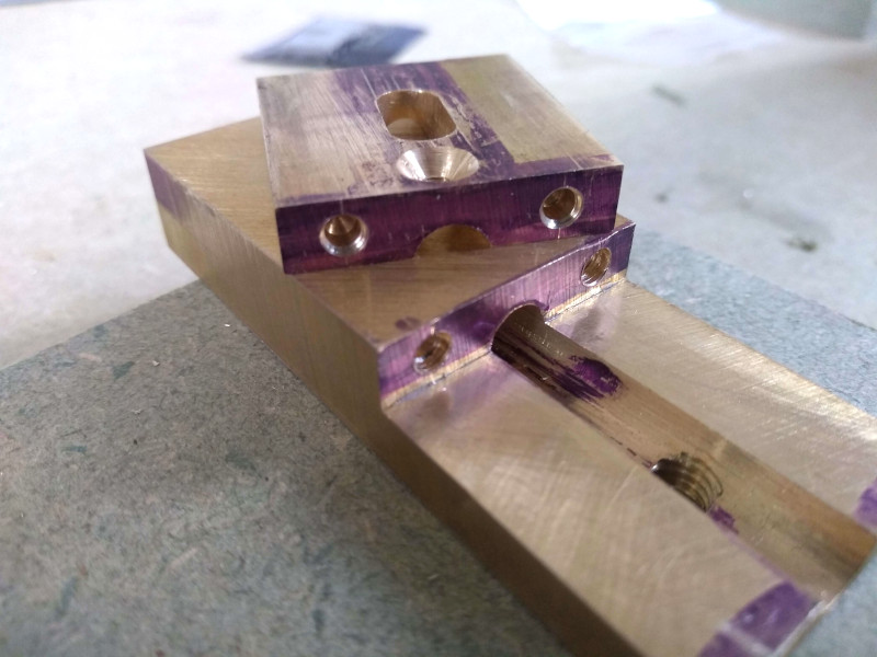
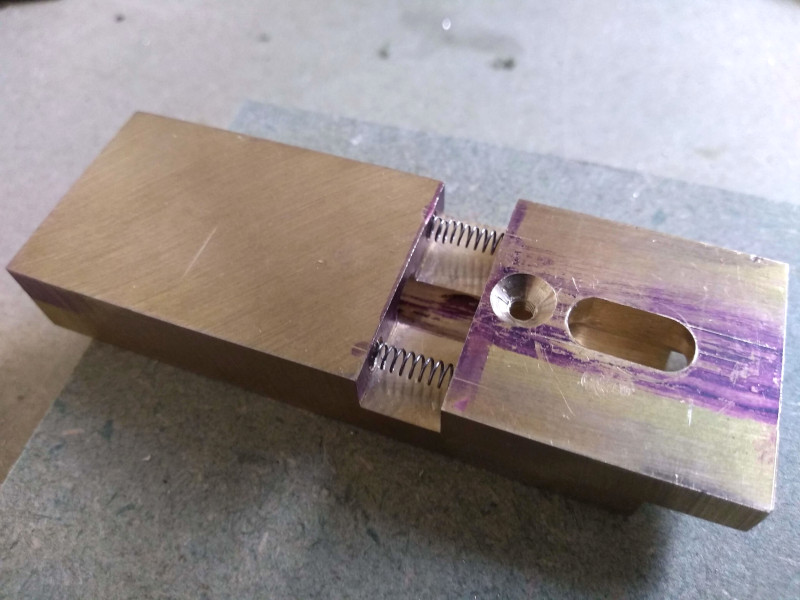
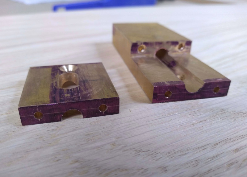
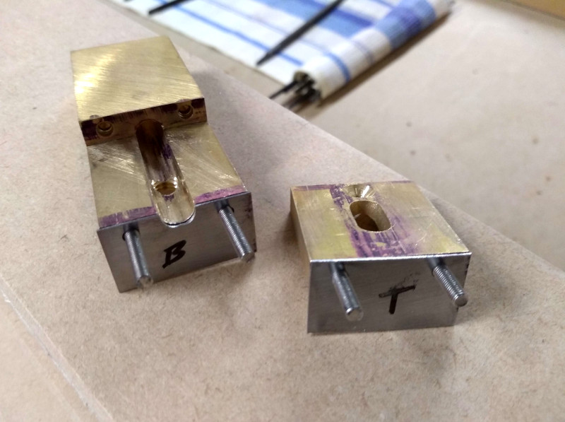
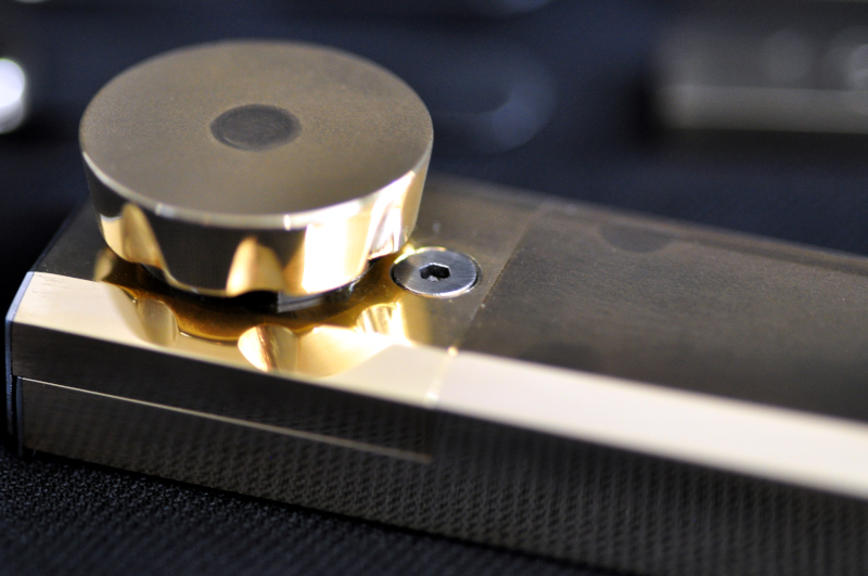
This smaller piece of brass will form the front slide, and will sit at the front of the guide to hold one of the guide plates, this plate is what the hacksaw will ride against.
I drill two holes

rGLZdl3.jpg


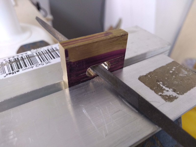
And file away the center to leave an elongated hole that will let the front slide move forwards and backwards on the locking bolt.

50vmDQP.jpg


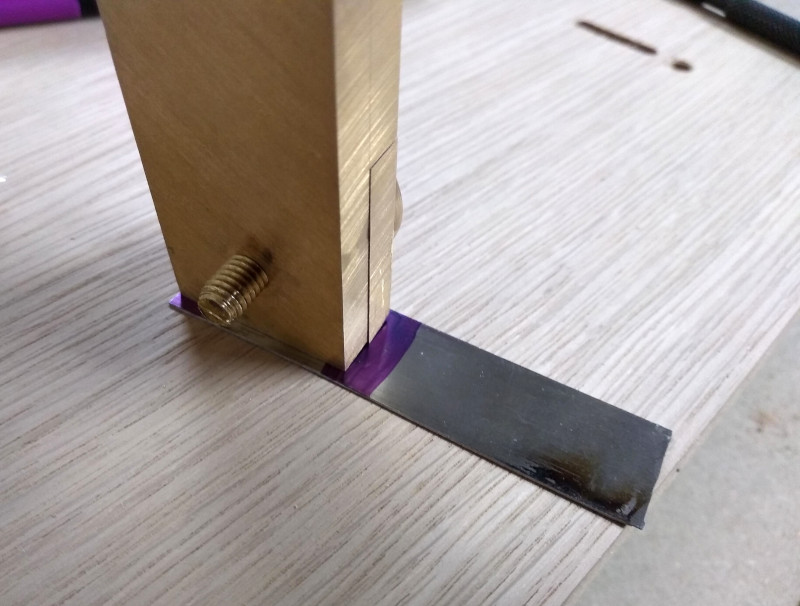
Next I removed the head from a bolt and drilled and tapped for a smaller countersunk bolt to fit into it’s centre.
This will secure the front slide to the bolt. The threaded end of the bolt will hold the guide adjustment thumb screw.

PukDqGF.jpg


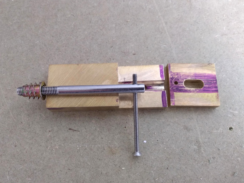
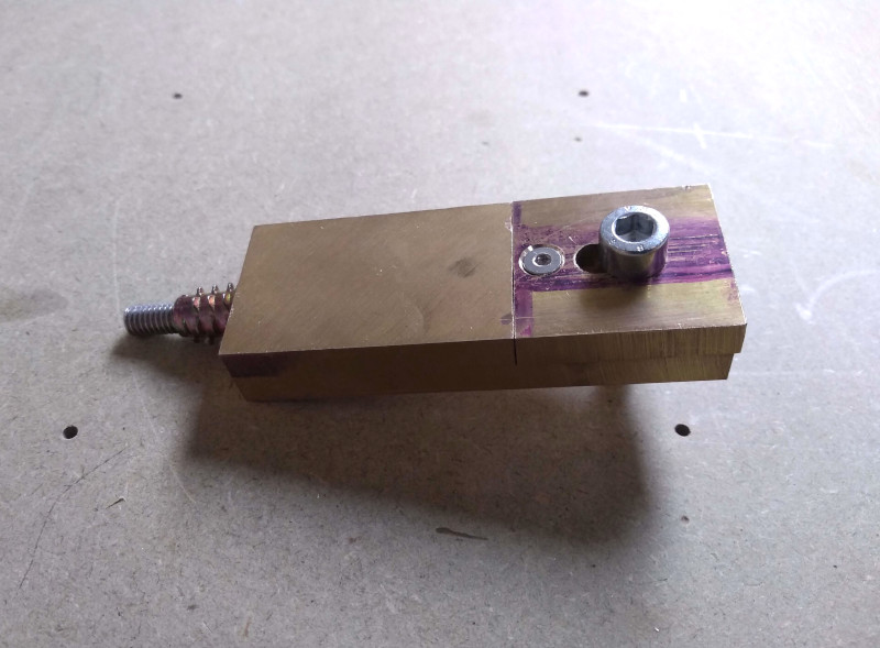
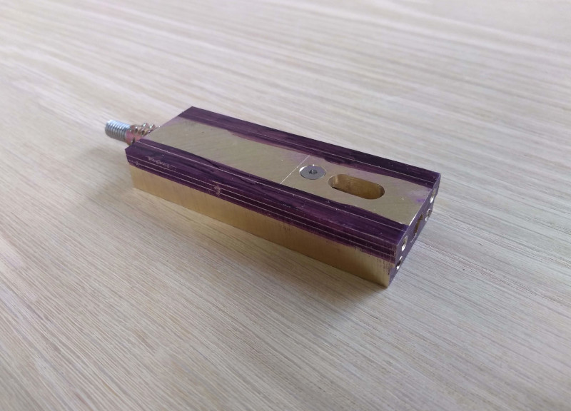
A dry fit of the main components to see how they fit together, temporarily held in place with a cap bolt.

L4JkQDO.jpg


Next I needed to make the locking thumb screw for the front slide.
I’ve no access to a lathe so had to get creative with the pillar drill.
Not ideal and quite limiting but it did what I needed to do...just about.

iAxxqfU.jpg


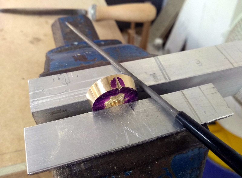
I cut the shaped piece from the rest of the brass and began to file the finger indentations.

eL5Tvht.jpg


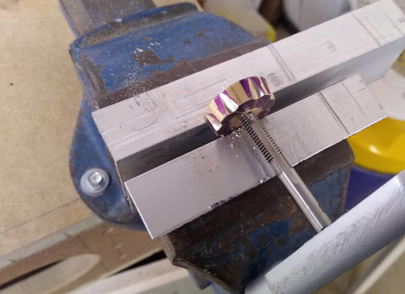
And then tapped the centre

wcAB9lF.jpg


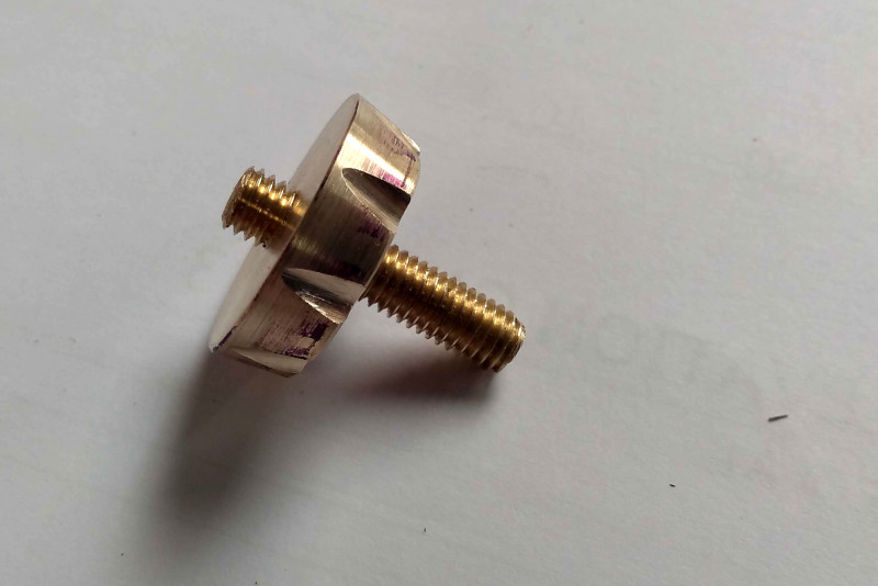
Next I threaded a short piece of brass rod, this will later be peened permanently into the thumb screw.
This thumb screw will be used to lock the front slide in position once the guide has been set using an indexing plate.

s4fruWl.jpg


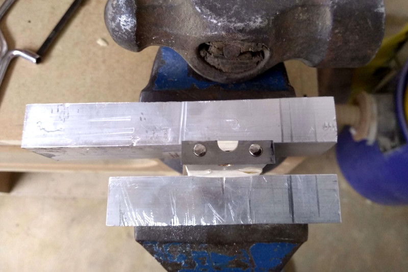
Here I’ve drilled two holes in the front slide and two corresponding holes in the main body of the guide to accept compression springs.

nTguCoY.jpg

EP1ZRTL.jpg


Next I mark out the guide plates on a piece of high carbon steel.

TbrP68G.jpg


I drill holes in the front slide and main body and then tap them

jhYyLR6.jpg

zJZcuNj.jpg


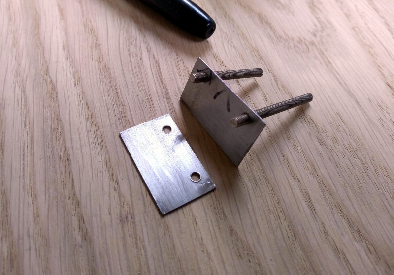
The holes accept bolts that fit through the guide plates, these will later be peened into position.


gK1VGa8.jpg

YUUydqM.jpg


Next I fit the body of the guide back together and square the sides. I then mark out a bevel on the top of the guide.

hy3HzXz.jpg
 
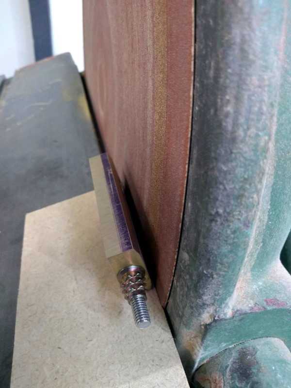
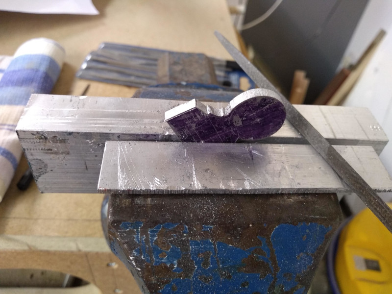
I use the disc sander to remove the bulk of the material then come back to finish with hand files.

HkY1kOy.jpg


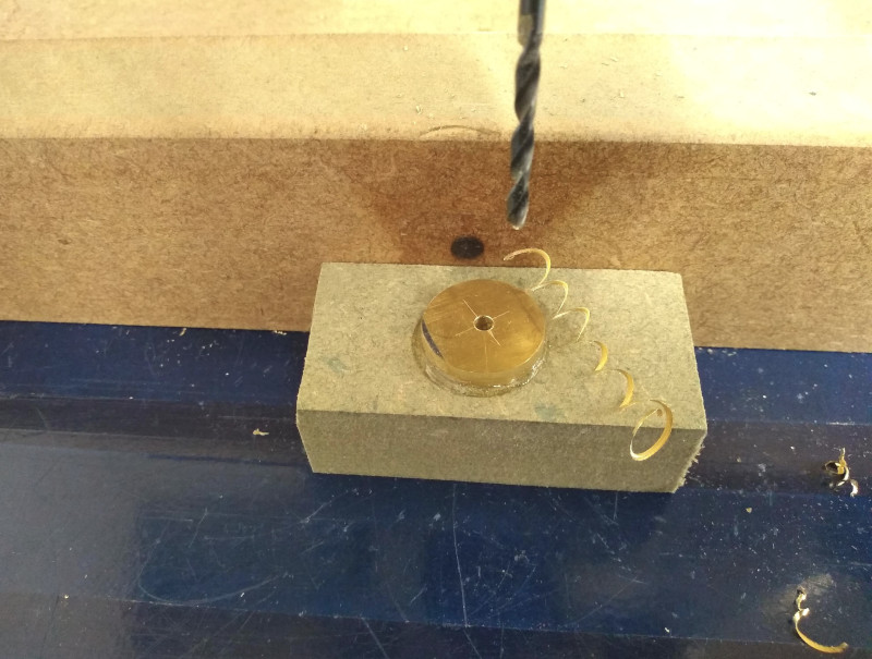
I cut a circle from a piece of flat brass stock and shape it with the disc sander to form a collar. I used superglue to secure it to a piece of MDF and drilled the centre.

eASLIaf.jpg


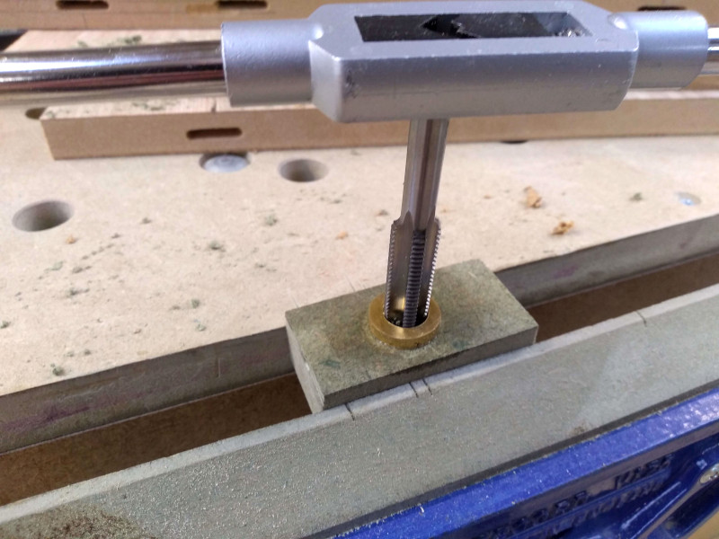
I tapped the centre to accept a threaded insert.

62VZs3f.jpg


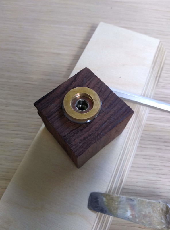
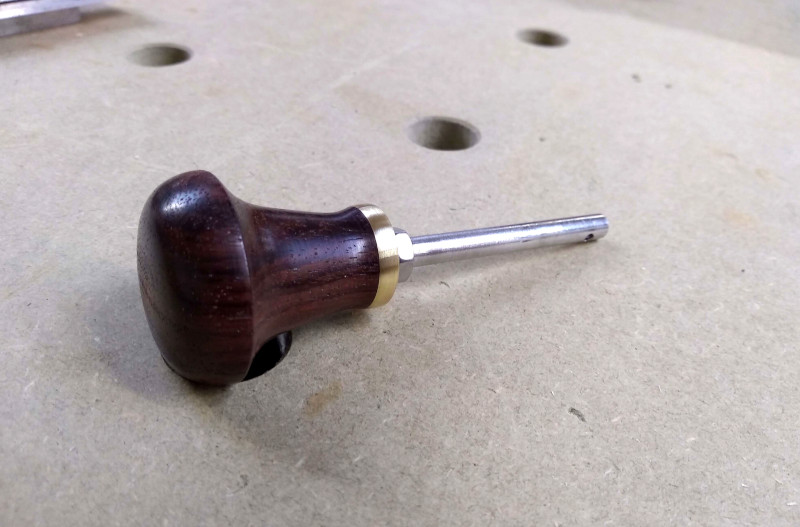
I then used the threaded insert to secure the brass collar to a piece of rosewood, I also used a little epoxy to help hold it in place. This will be made into the handle for the guide.

lbm3d5c.jpg


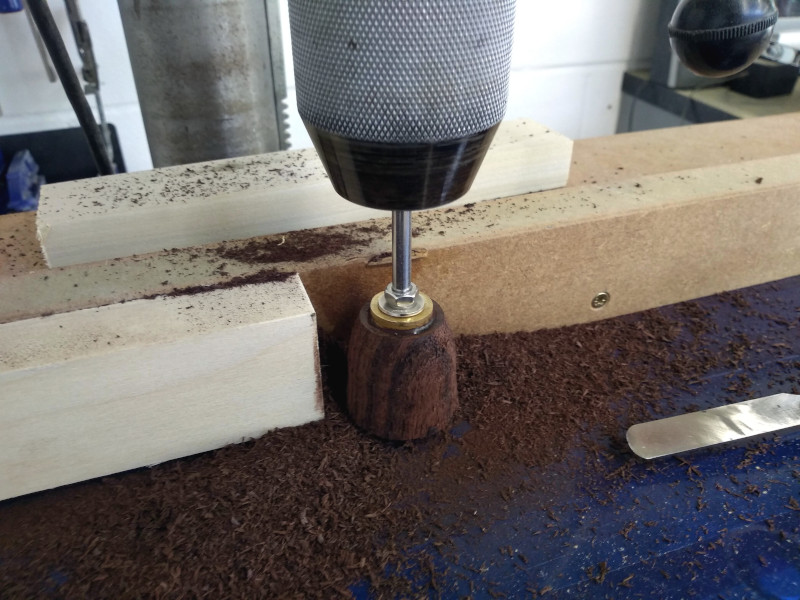
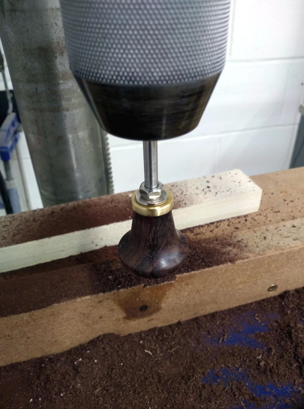
Back to the dubious pillar drill to start shaping the handle. Really missing the lathe,

1YCVvXa.jpg


but after a little perseverance the handle was done.
I buffed it with shavings

ndBswkl.jpg


Then added a coat of sanding sealer. I’ll later finish it with resin epoxy.

v65n5sV.jpg


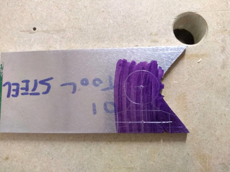
Next I make out the handle support on a piece of 01 tool steel.

6yiz9qI.jpg


I cut it out with a hacksaw and shape it with hand files.

t3QNEhJ.jpg


I then drill and counterbore the holes to accept cap headed allen bolts.

TSirUDy.jpg


And finally I drill and tap the fixing points in the main body of the guide for the handle support to secure into.

19oKE3q.jpg


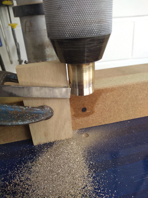
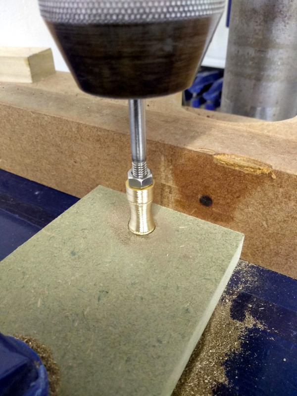
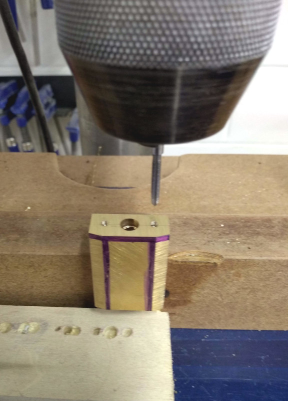
Back once again to the “pillar drill lathe” this time I have a piece of brass round bar which I have drilled and tapped the centre to accept a bolt. Using this bolt I can mount the piece in the drill chuck and start to shape the adjustment thumb screw which will sit at the rear of the guide.
I had to add a supporting piece of MDF at the bottom while shaping the thumb screw as there was a lot of deflection.

z9O5TU2.jpg


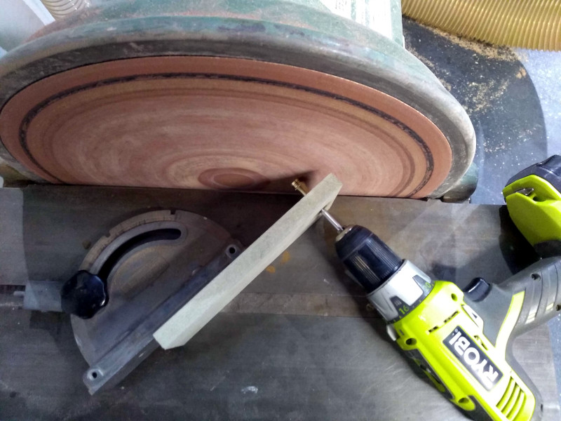
The deflection meant I couldn't finish the end of the thumb screw as desired so I turned to the disc sander with a simple jig to add a bevel.

ZXuBYJQ.jpg


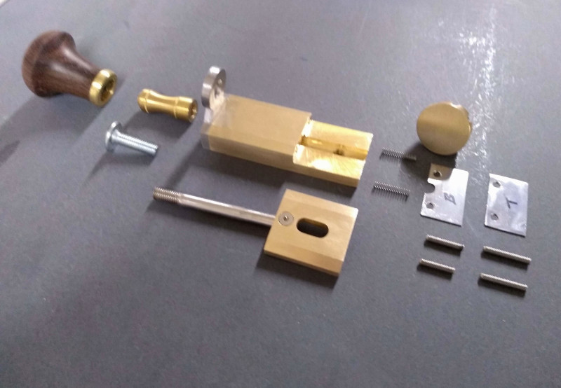
All of the main components to the guide are now complete. They still require a lot of work to clean up and finish.

LZDeoEx.jpg


But I can fully assemble the guide for the first time.

Gmk36u9.jpg


Lastly I could add the guide plates. I inserted the bolts and used high strength lock tight to hold them in place.


Newm1Tv.jpg


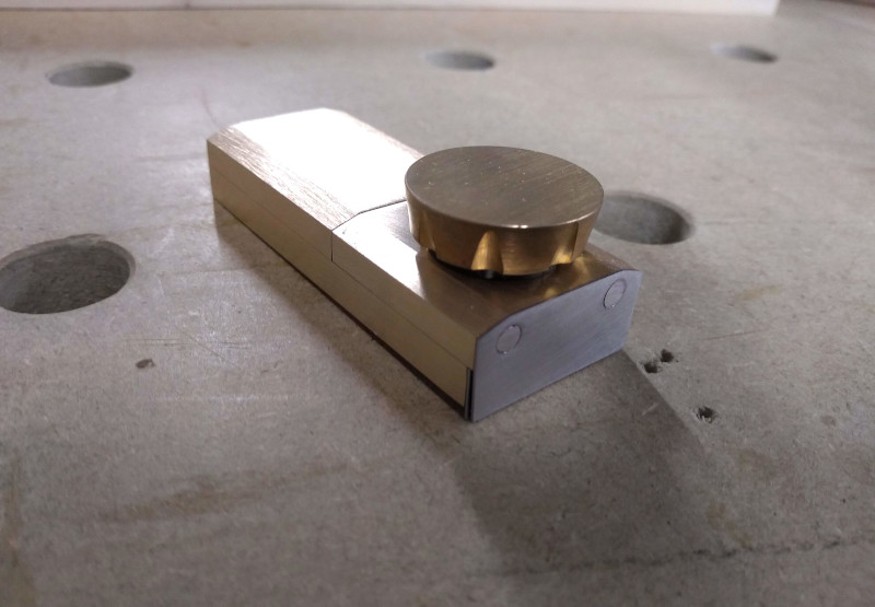
I then cut down the surplus bolt and peened the plates into position.

YqIsFOr.jpg

TM59bfm.jpg


With the majority of the guide complete I could start work on the indexing plates.
These are used to set the guide to a desired TPI.

I start by cutting and rounding some brass flat bar.

sNtl59c.jpg


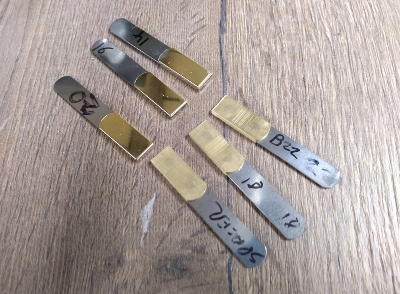
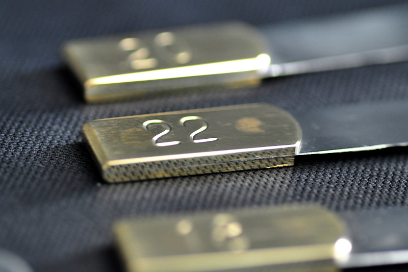
I needed some precisely thicknessed metal for the indexing plates that was strong and durable. I had no way of making such pieces myself, so my first thought on what might be suitable was feeler gauges.

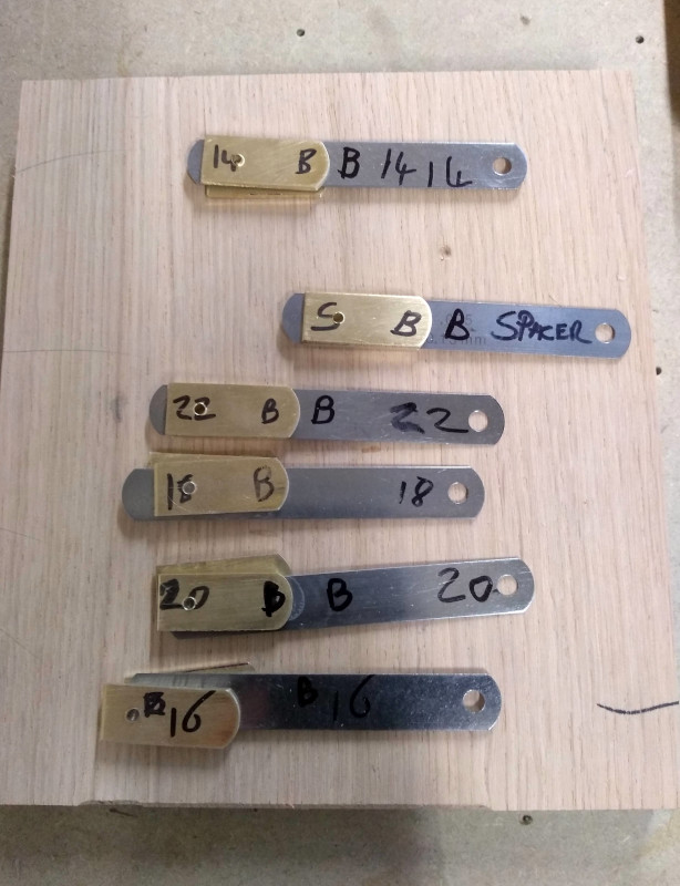
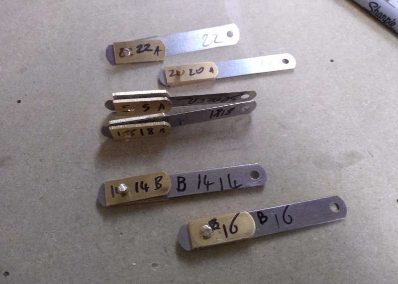
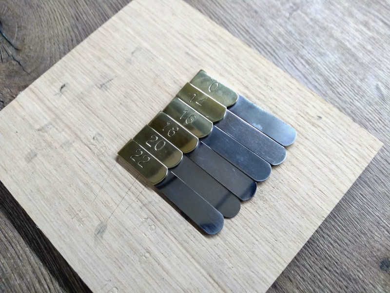
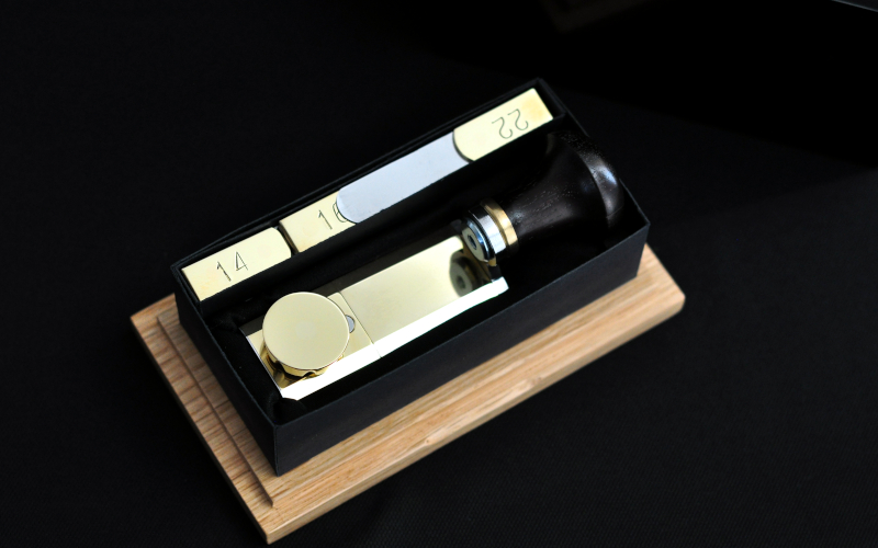
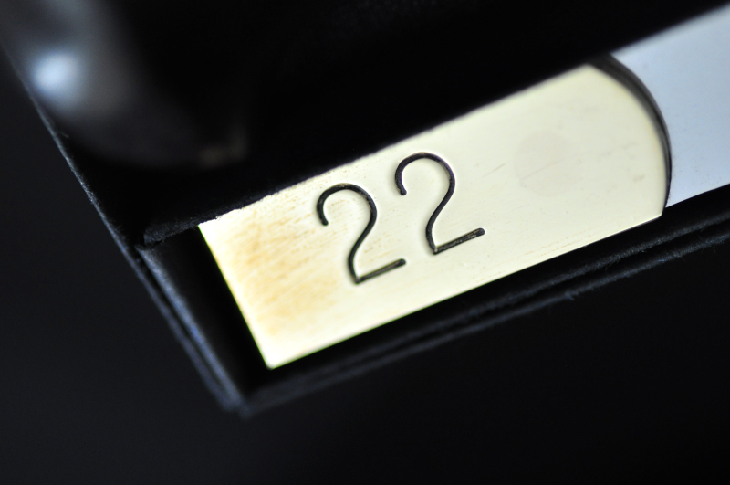
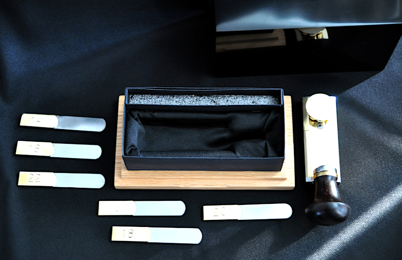
I bought a large set of gauges and after a lot of testing found the right thicknesses to accurately set the guide at 22, 20, 18, 16 and 14 tpi, these can also be used in combination to set the guide at smaller tpi ranges. I also included a 0 indexing plate that can be used to finely adjust the guide.

I then marked out and carefully drilled holes through the brass plates and gauge

QPKgnAg.jpg
 
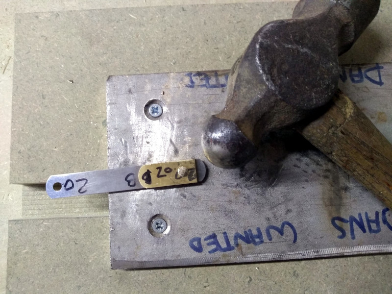
I cut small pieces of brass rod which was used to peen the plates to the gauge.

6Z0ZSbd.jpg

i3DG1Zj.jpg


I used the disc sander to remove the surplus brass, then finished by hand before finally buffing with a loose mop.

RO8nbQB.jpg


Lastly I stamped the relevant numbers into the brass plate. I would have liked to etch these numbers instead of stamping to achieve better accuracy, however lock downs where in place so I was unable to see my friend to arrange the needed stencils.

0hJENxo.jpg


With all of the work done I could finally start to finish the individual pieces.
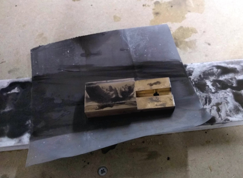
I used wet and dry sandpaper, working up through the grades on each piece.
It was a messy process!

Zzyjn71.jpg


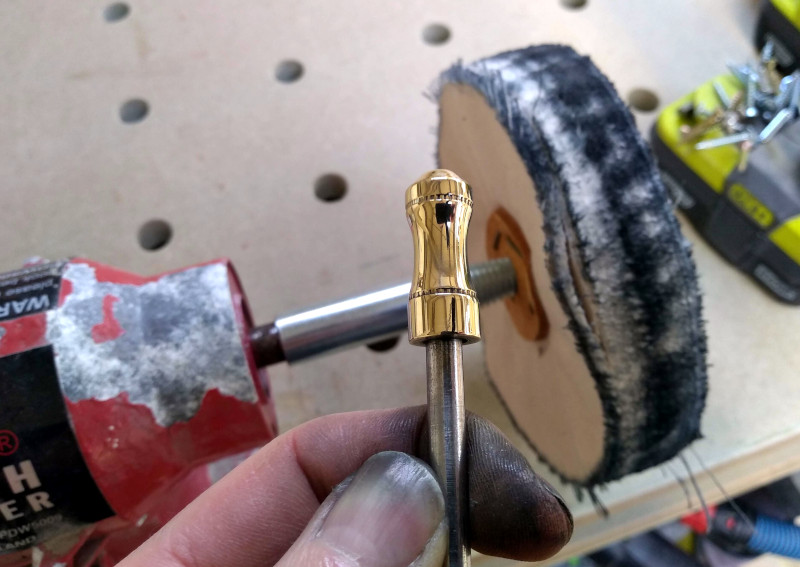
I used a combination of stitched and loose mops to buff everything to a gloss finish.

DDoIs0o.jpg

LD18i5e.jpg


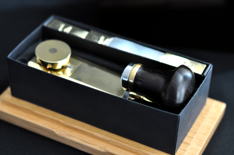
With everything finished and polished I could finally fully assemble the guide, but before that I had to make a box for it to live in.

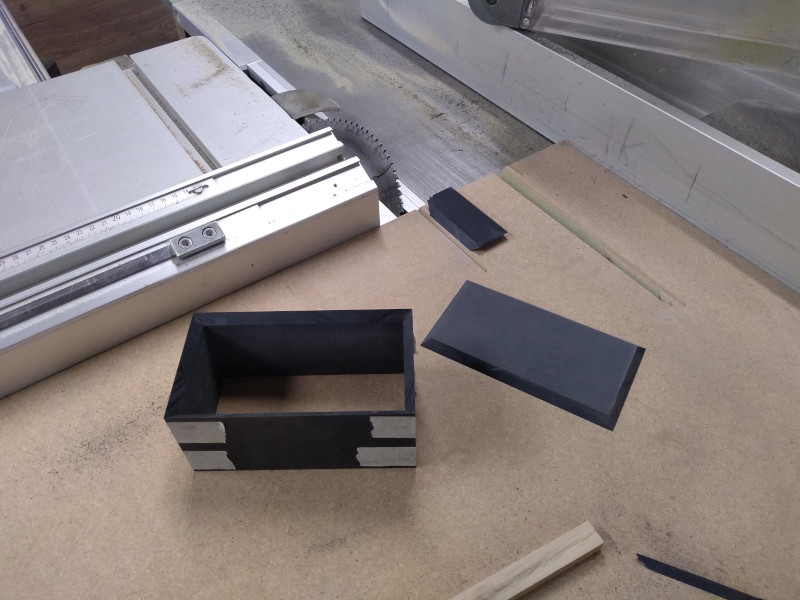
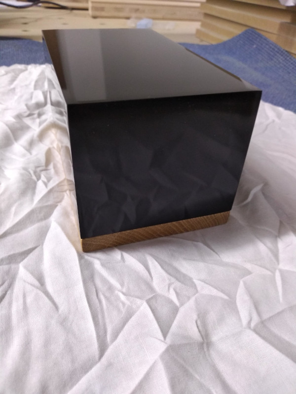
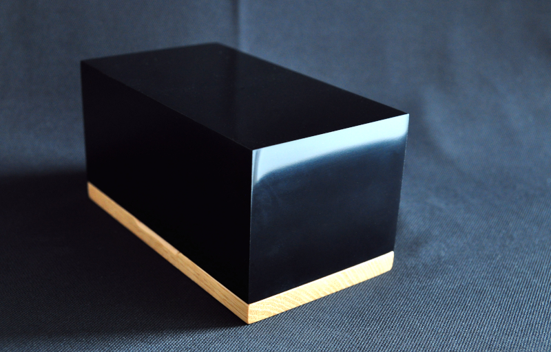
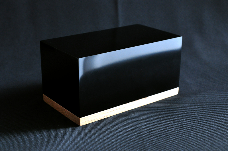
I had some pure black Corian left over which I was able to cut 4 sides and a top from.
I mitred the corners of the box and also the top edges in the hope to make the box seamless.

vOw84io.jpg


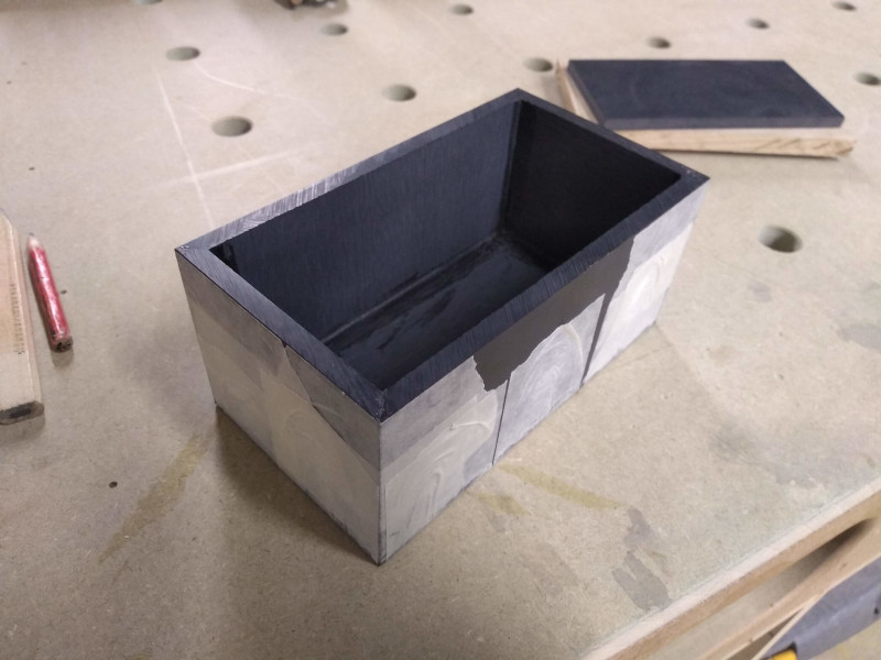
I used masking tape and Corian resin to fix the box together.
The masking tape hides the joints while the glue is setting so I had to wait until it was fully cured before I could see how well they had turned out.

b4M8FEU.jpg


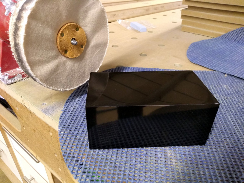
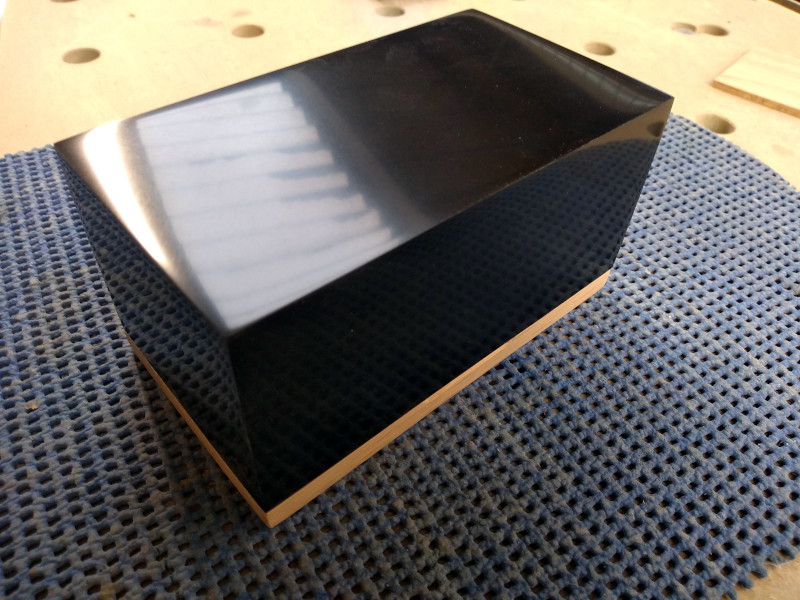
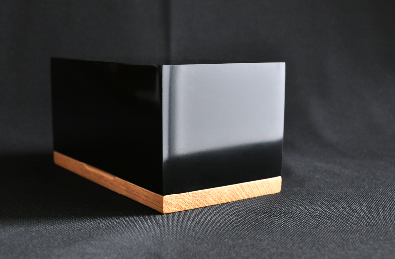
Thankfully they had turned out nicely so I set about sanding the box from 120 grit all the way up to 3000 grit. This was a bit of an experiment as I wanted to see if Corian could be polished to a very high gloss finish.

After sanding I used the loose mop and a jewellers compound to buff the Corian.

lvpfFkV.jpg


Thankfully after all of the effort in sanding the Corian buffed up to a nice high gloss finish, I was relieved!

l0eAQuw.jpg


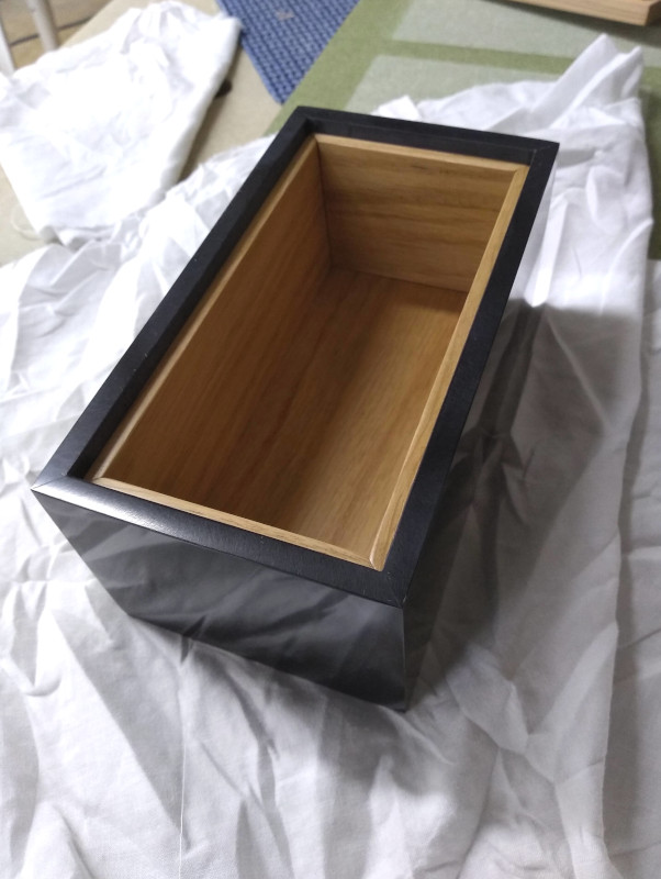
I added an oak interior to the box and made a matching oak base which I rebated to allow the box to fit snugly onto.

9RjkkJc.jpg

XmMo1Bg.jpg


Lastly I needed something to secure the guide inside of the box.
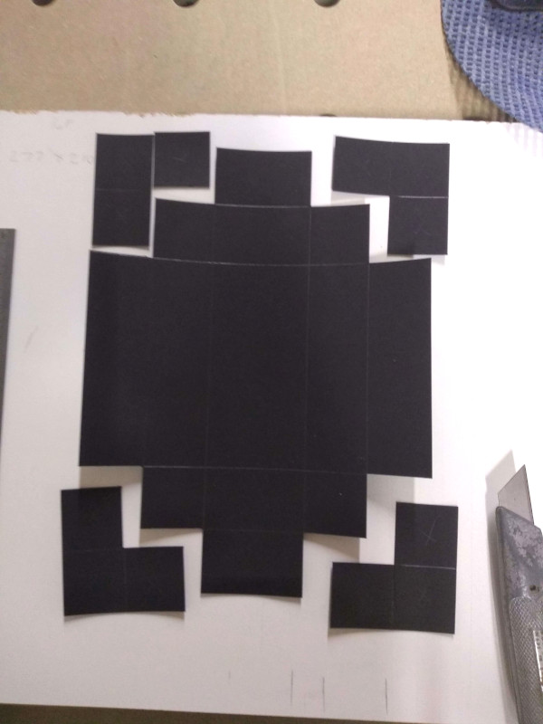
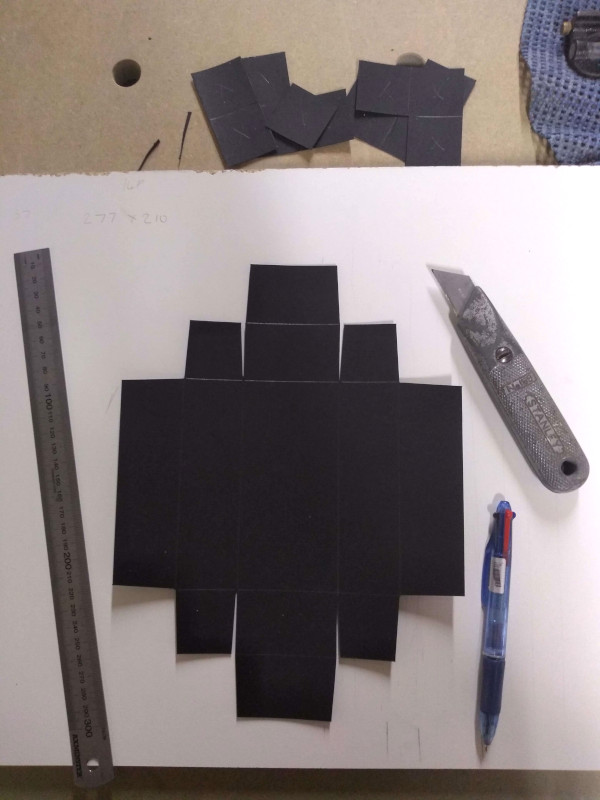
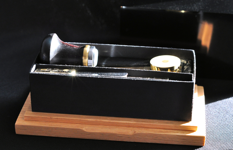
I bought some high quality 350gsm card to make an inner box for the guide.

I marked out and cut away the relief angles

IdkHMbx.jpg

und09IV.jpg


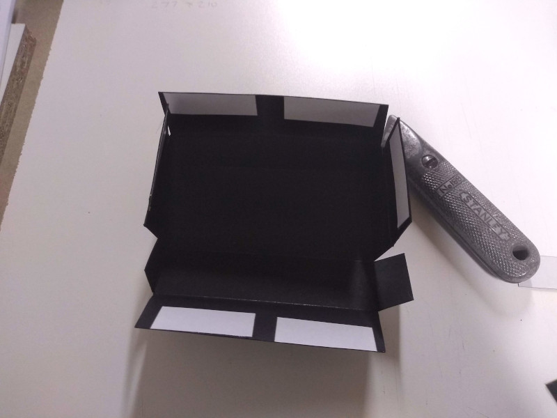
I then started to fold the box into position and used double sided tape to hold it together.

QE90X8j.jpg


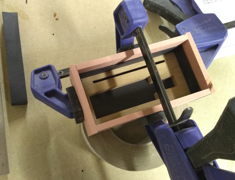
With the card box held together I made another piece of oak to sit in the bottom of the box. I made this with a cut out so the guide could sit tightly inside of it.

I then glued the oak into the card box using scrap pieces of MDF to hold the box in position.

fmHggkz.jpg


I then screwed the card box securely in place to the oak base.

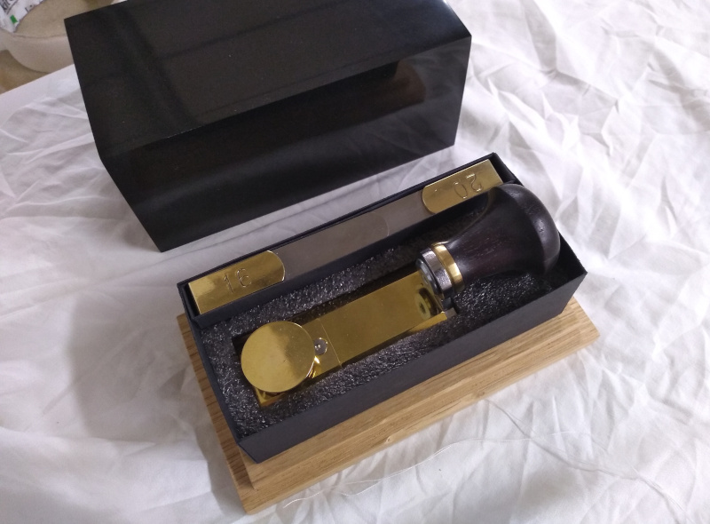
I made a smaller card box in a similar fashion to hold the indexing plates and then added some foam to the box to hold the guide in place.
I later covered the foam in faux suede to finish the inside of the box.

5SESaAN.jpg


And very lastly I could assemble the guide!

FAkxRxo.jpg

JCdtdpb.jpg

3Xq6Ot1.jpg
 
After a final polish up I had to take some pictures before its first use.

HwYNBxN.jpg


10QN9ii.jpg


3ULIQXp.jpg


2gSkTc2.jpg


OXkiSac.jpg


owYcewK.jpg


jnOwEYW.jpg


Uxn04Xv.jpg


LGrISxy.jpg


e6kq5vn.jpg


s0bBpMe.jpg


PJ9bpav.jpg


6dl99Ox.jpg


L4ESxGu.jpg


This project turned out to be a lot more work than I had anticipated but I really enjoyed making it.
It threw up a few challenges along the way but I like to come up with ways to try and get over them, that's part of the fun!

Thanks for taking the time to read through this post and I hope you have found it interesting.

Below is a video demonstrating the guide in use if you’re interested to see how it works.


Cheers
Dan.
 
Dan, that toothing jig is an amazingly clever bit of work! You haven't shown the underside of the jig, but I assume the thin plate on the"inside" is what catches in the preceding saw cut? I get the general principal ok (I think!). I had a twinge of envy watching you working on small teeth without any visual aids - a head loupe has been mandatory for me for many a year - even for 10-12 tpi!

Marking out from a paper template is tedious, but I don't find it too hard to do with a needle file up to 18tpi. You can usually correct small errors when filing to depth. I like to cut the teeth progressively, just making one or two strokes per tooth depending on size, because I find it easier to watch the diminishing flats & make any necessary corrections as I go. Cutting to full depth before moving to the next tooth is a sure recipe for cows & calves for me. I don't like paper templates much either, but occasionally find it necessary, when setting out a spacing for whivch I don't have a metal guide. If you have to use paper, strip it off as soon as you have set out, otherwise the paper gets in the file teeth & makes it harder to file consistently.

I don't know how you blokes persuade a hacksaw to cut saw plate effctively - you must get better blades in your part of the world. I tried hacksawing out the plate for the first saw I made, many years ago, & apart from the intolerable screeching, the number of blades I went through was ridiculous. I would have given up any thoughts of making saws if someone hadn't directed me to 1mm cutoff wheels!

I was surprised when you said the needle files have too big a radius to cut 20tpi teeth. I have found them to have much sharper corners than the supposed 4" DEST files I can get here (which last less than half as long as the Grobets!) I rarely cut teeth finer than 18tpi, for which a #4 Grobet is adequate imo. Out of curiosity, I grabbed an old 24pi hacksaw blade for a template, and toothed up a bit of shim plate just to see what the geometry looked like:
24tpi.jpg


The piece is only 0.010" thick and despite the well-used 4-cut file I used, it still only needed 2 strokes to cut each tooth on such thin material. This illustrates what I said earlier about being hard to keep consistent if you cut the teeth all at once. Because I just wanted to see what the gullets would look like, I made both strokes before moving on & as you can see, my teeth are a bit uneven. The gullets are maybe a teeny bit bigger in area than the teeth, but they are within my tolerance range. However, I would agree they are at or about the limit for this tooth size - I'd want something finer in the (highly unlikely) event I wished to cut 32tpi. Some argue that a large gullet is actually good because it carries more sawdust and the rounded bottoms resist tooth-cracking better, but like you, I'm not too keen on saws that are all rounded gullet & tiny little stubs of teeth either.

Keep up the good work!
Cheers,
Ian


Write your reply...

Latest posts

Back
Top