Farm Boy

UKworkshop.co.uk

Help Support UKworkshop.co.uk:

This site may earn a commission from merchant affiliate links, including eBay, Amazon, and others.

Dalboy

Established Member
Joined
18 Sep 2008
Messages
3,935
Reaction score
304
Location
Canterbury United Kingdom
I was asked to post this, not sure if here under projects or in the metalworking heading. For a while now, I have been building a model of a Farm Boy hit and miss engine with thee hope of getting it running at the end.

Just a few photos of the work so far as there are a lot if I was to post all of them. This is made from bar stock except the two flywheel.

Front body shaped.JPGDSCF3063.JPGDSCF3083.JPGDSCF3095.jpghopper machining (3).jpgHopper machining (6).jpgJoining rear and front base units (3).jpgcon rod (3).jpgcon rod with bearings (1).jpg
 
Last edited:
Nice work.
Out of interest how did you approach the silver soldering?
I have found that for fiddly jobs like this the paste is really good, although how they justify the price is beyond me.
And just being nosy how do you find the lathe, guessing a Warco from the colour?
I am a big fan of big old British machines, but well aware that the Chinese ones are getting better and better.
Would be interesting to hear your views as the owner of what looks like a relatively new one.
 
Thank you guys no work on it today had a company to grind a stump out.


Nice work.
Out of interest how did you approach the silver soldering?
I have found that for fiddly jobs like this the paste is really good, although how they justify the price is beyond me.
And just being nosy how do you find the lathe, guessing a Warco from the colour?
I am a big fan of big old British machines, but well aware that the Chinese ones are getting better and better.
Would be interesting to hear your views as the owner of what looks like a relatively new one.

I have a tub of powder that I mix as needed so can make as little or as much as needed also have different grades of silver solder. I did the governor arms while the ring was still attached to a larger piece, then bored the centre hole and parted to length.

Lathe is good but have a couple of gears stripped (My fault) here are a couple of pictures of my main equipment I an using on this build

20210930_164147.jpg

20210930_164150.jpg
 
Thank you guys no work on it today had a company to grind a stump out.


I have a tub of powder that I mix as needed so can make as little or as much as needed also have different grades of silver solder. I did the governor arms while the ring was still attached to a larger piece, then bored the centre hole and parted to length.

Lathe is good but have a couple of gears stripped (My fault) here are a couple of pictures of my main equipment I an using on this build

View attachment 189923

View attachment 189924
Very similar here. I have an Amadeal 25 milling machine, very similar to yours.
Wish I had gone for the three way dro. I decided to use the inbuilt one for the quill and just fitted a two way dro set up. The quill one is actually a bit awkward to read I find.
Have a Harrison 5a lathe.
And have a little Clarke 190 bandsaw, modified to run at metal cutting speeds.
You are much tidier than me :)
 
Thank you guys. Not a lot to report as I am doing silly little bits and making small pins. Going through the plans and double-checking what else needs making. Getting very near the end, still need to sort out the electronics to get it running, as well as make a fuel tank and base.
 
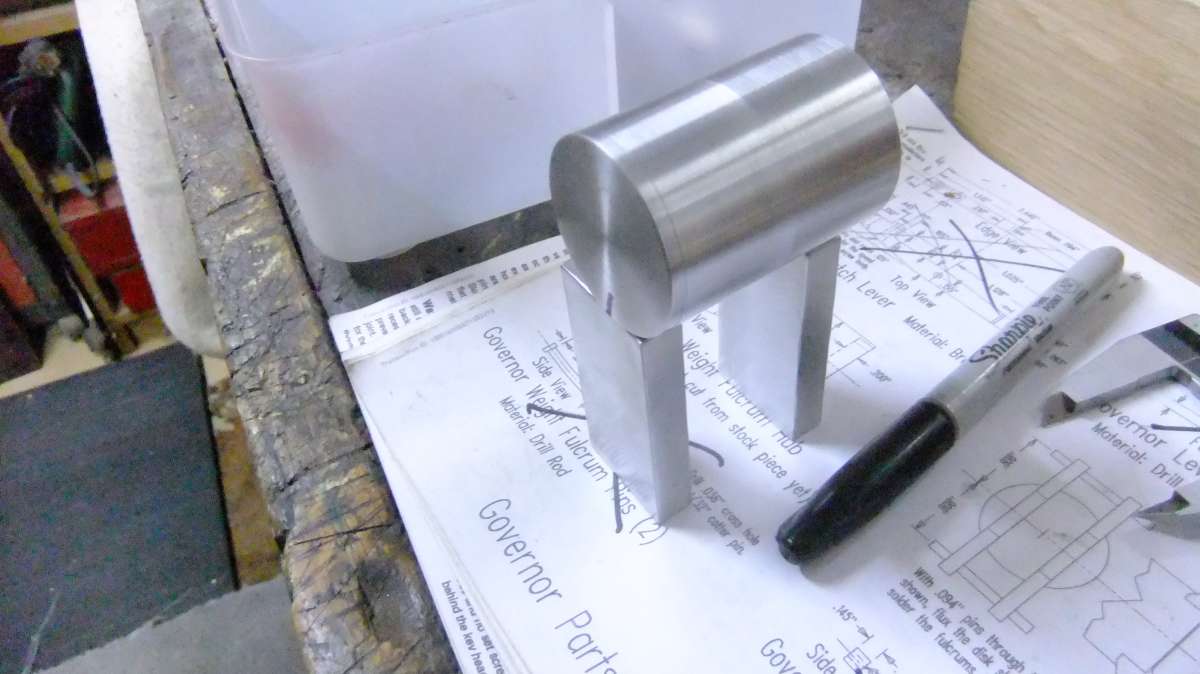
Not done much lately. But I have made a start on a fuel tank. Turned the main body and ends which is a cylinder at the moment need to make a filler cap and fuel cut off outlet.


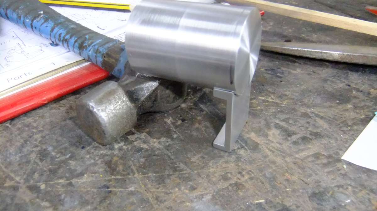
Tank sitting on two blocks which will become the supports


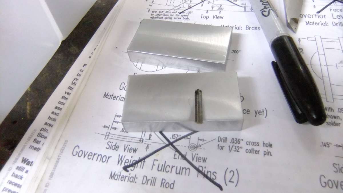
fuel tank support (2)


The supports cut from a larger piece which had some holes luckily the hole shown is machined out


fuel tank support (3)


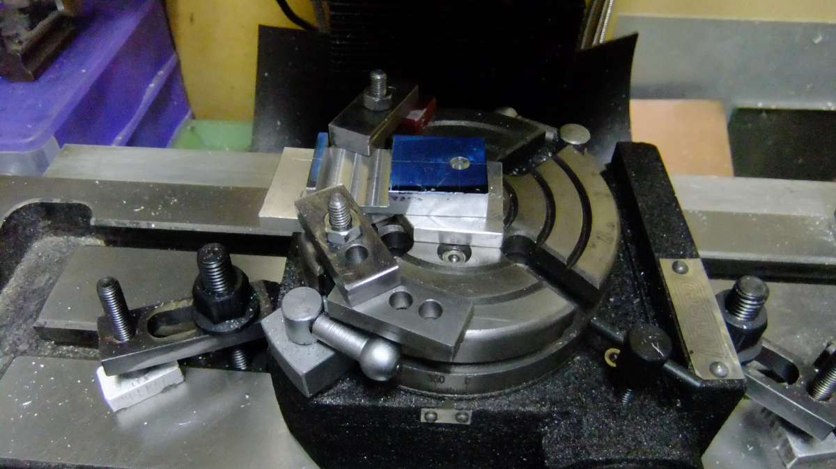
Here I had machined out the bulk of what was not needed ready for some shaping.


fuel tank support (9)


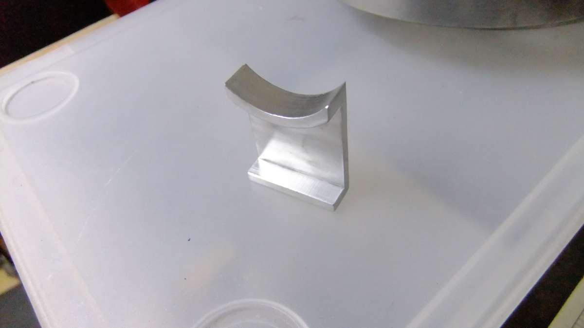
After machining the curved section, they are now a lot shorter but still leaving enough room for an outlet from the tank.


fuel tank support (4)


By machining them instead of using solid blocks makes for fixing to base and tank a lot easier as well as lightening the appearance of them.


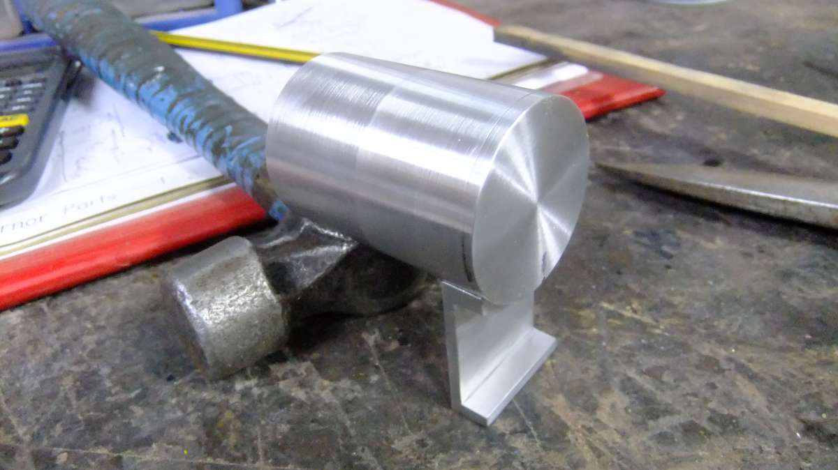
A test fit of one of the supports, not sure which will look better, the foot facing in or out. Facing in would give a little more room for the outlet if I need to work on it when it is complete.


fuel tank support (7)


fuel tank support (6)
 

Attachments

  • fuel tank support (2).JPG
    fuel tank support (2).JPG
    2.1 MB
  • fuel tank support (3).JPG
    fuel tank support (3).JPG
    2.1 MB
  • fuel tank support (4).JPG
    fuel tank support (4).JPG
    2 MB
  • fuel tank support (6).JPG
    fuel tank support (6).JPG
    2 MB
  • fuel tank support (7).JPG
    fuel tank support (7).JPG
    2 MB
  • fuel tank support (9).JPG
    fuel tank support (9).JPG
    2 MB
Not been in the workshop much as sorting out my rear lights on the car as a Morrisons van decided to back into it outside the house.

DSCF4130.JPG


More work on the Fuel tank. First a little late I managed to get both stand uprights completed, all except the fixing holes. As well as the end cap fixing screws.


Fuel tank 2 (2)


Onto the tank once again drilled the filler hole and fuel outlet this was threaded 1/4″ x40. Turned some brass for the outlet elbow and did the same method as I did for the carburettor elbow by milling at 45deg most of the way through heating and bending before silvers soldering.


Fuel tank with outlet fitted (1) Fuel tank with outlet fitted (4)


Twisted the tank upside down to show the outlet pipe in position. I need to take apart to clean swarf out of the inside


Fuel tank with outlet fitted (5)
 

Latest posts

Back
Top