Forged hold fast's

UKworkshop.co.uk

Help Support UKworkshop.co.uk:

This site may earn a commission from merchant affiliate links, including eBay, Amazon, and others.
Mr_Grimsdale":1ki65yun said:
If stable but not flat you work out how and where to plane by looking at it when held freely i.e. not clamped, and not relying on the flatness of the surface.

If you want to plane in the middle, and your bench is concave, thou art bugerred.

So I stand by my claim to require a pretty flat bench.

I could bodge around it, by using wedges and shims and planing boards and stuff, but I'd rather (simply?) have a flat bench.

Also useful when using scribing gauge techniques stolen from our friends the metal workers.

BugBear
 
Mr_Grimsdale":mnwvjiri said:
bugbear":mnwvjiri said:
Also useful when using scribing gauge techniques stolen from our friends the metal workers.

What's this then? Please tell tell me more.

A scribing gauge is a simple "point on a stick".

In use, the work piece is fixed (by whatever means neccessary) to a flat surface.

Since the workpiece is now in a "defined" relationship with a flat surface, the scribing gauge can now mark the workpiece by reference to the surface, not the workpiece.

This can (sometimes) provide a unique means of marking.

For example, if the "nominal" reference edge of the workpiece isn't continuously straight, a normal gauge won't do.

Or if the workpiece is a funny shape, a surface gauge will reach into even more places than a pattern maker's "grass hopper" gauge.

For example, if you had made a skewed, but flat cut on one end of an irregular (e.g. sculpted) log, how (otherwise) would you mark a parallel flat cut, 1 1/2 foot away?

It's a powerful technique to tuck away in your armoury.

(with reference to the stock prep issue, it would allow you to chock or wedge a workpiece, and then trace a perfect "planar" line around the periphery)

BugBear
 
Heres My way of using bugbears technique

feet2.jpg

feet1.jpg


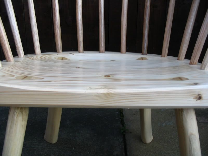
My refernce plate is a 2 inch tick concrete slab. I use wedges to level up, using the mortar lines on the house as a sight or a stabila level if I want to be especially acurate. I use a block and run the pencil on top of it and scribe round the ends of he legs then trim them off and the chair or stool will always lie level without rocking :lol:
 
Bugbear,
Judging by your relative silence recently, have you been on holiday?

Scribing parallel lines from the bench surface can be very useful if you want to see how thick a board it is possible to get from a twisted or wavy plank.

I think we are all agreed that flatness is important, whether one chooses to hammer in nails etc is just down to personal choice, but does not seem to meet the 'Peters' prescription.

David C
 
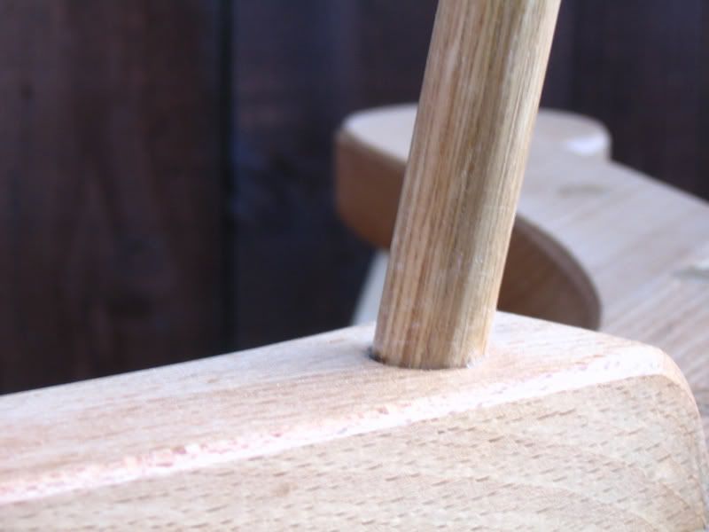
Jacob, that was a chair I made with plain seat, rived legs and spindles, and a 3 part arm

welsh2.jpg

welsh5.jpg


Theres a few types of timber framing layout where you create an imaginary virtual "reference surface" that you visualise within the beam and temporily mark, and mark mortices and tennons from that :D
Square rule "imagines" there to be a perfect PSE timber encased within a rough out of square beam, so you work from that for marking lengths and positions of mortices and tennons so they line up despite waney edges/twisting/bowing etc. The virtual reference surface becomes an actual surface for all tenon shoulders to lie on.
scribe rule is happy to let a rough out of square beam stay as such structurally and just imagines a plane that cuts through the beam and you mark your joint positions from that, all the timbers are laid out relative to each other in a perfectly horizonatal plane over a full size rod while the joints are scribed (basically like doing skirting boards) you can get tennon shoulders to wrap perfectly round out of square or even wany beams Then when its all draw pegg'd up it'll assume its horizontal form 8)
Cheers Jonathan
:D
 
For a valuable highly figured hardwood plank. a little extra time spent, to get the desired thickness is well worth the effort.

Again we diverge because of the differences between cabinet and joinery work!

David C
 
mr spanton":3o8esgwm said:
Heres My way of using bugbears technique

My refernce plate is a 2 inch tick concrete slab. I use wedges to level up, using the mortar lines on the house as a sight or a stabila level if I want to be especially acurate. I use a block and run the pencil on top of it and scribe round the ends of he legs then trim them off and the chair or stool will always lie level without rocking :lol:

Very neat - and hard to do any other way.

Here's the posh version of a point on a stick (cheap at boot sales if you wait long enough, and buy rusty enough)

http://www.wdynamic.com/galoots/4images ... ge_id=4038

BugBear

(PS - those were more 1/2 meg photos, Mr Spanton...)
 
Intertesting picture Bugbear. My wife used to use a similar device for dressmaking to get hemlines parallel to the floor :lol:
What would they use that for in engineering then?

PS I can see what you and Mr charlesworth are saying about a flat flat bench, its like the bench is like the table on a jointer machine where flatness is transferred to the stock through the table surface. But I think theres also a case as Jacob said to rely on your eyes and feel and work to a marked line as well. And as he said a flat bench is no use until you have a good flatted face to place on it any way, then it comes into its own
I think its just a case of what level (sorry lousty pun :roll: ) or degree of flatness you think is necessary depending on the nature of your work.
Cheers Jonathan :D
 
Mr_Grimsdale":r7ypzm83 said:
Bit rough and ready and won't guarantee a horizontal top, but quick.

Yeah - again, it's not a matter of right/wrong, it's a matter of required accuracy versus hassle or time.

Of course, the slow *AND* inaccurate methods got weeded out years ago...

BugBear
 
I like 18th century technology.

I can understand and use it. (Unlike Pooters)

{The weedkiller obviously missed me!}

Silly me, I read that as slow and accurate please ignore pathetic attempt at joke.....

David C
 
Mr S. the marking gauge in metal working is one of the things that i
both have now, and used in the shop in the past.

remember that the basic premise in metalworking is that all
"reference" surfaces are flat and taken off a reference plate.
this is generally a cast iron plate which is accurately machined
to be flat within about 1 thou.

any holes to be drilled, or surfaces to be flattened too would be
marked from the bottom of the item, which was placed on the reference
surface. a nice coating of the wonderful engineers blue ( or where is it
these days :? :twisted: ) was placed, on the various surfaces to be
marked, and then when dry, the dimensions were set from the surface
on the gauge, and the scriber marked relevant points.

as with woodworking where possible you had two surfaces at right
angles with each other so that before all these modern machines,
you could for instance mark a cross for the centre of a drill hole.

or if you were filing down to a line, that would be marked by
the surface gauge too.


the relevance to cabinet makers is that of course you are only using
two surfaces to measure from, but metalworkers tend to use the
plate as the base not the material itself. therein lies the difference
from most woodworking.

if you follow D.C's method, your worktop is flat and thus can be used
as the reference, whereas i was taught that the woodworker gauges
of one side of the wood onto the other, rather than from the
reference surface.

hope that makes sense of part of it.

paul :wink:
 
morning Engineer :D
Thanks for that description. Its fascinating all these various aspects of technology that you can make use of to devise techniques etc. I sometimes think its a mystery why they work or how they work especially triangulation for creating rigidity, or why a circumference is 6 radius's, or why 3/4/5 makes a 90 deg angle? where does it all come from? :idea:
When you say "before all these modern machines" is that cnc machines?
Does the reference plate (even a virtual one) come into play when converting drawings into cnc data?
At one time I worked for the leading sign company in the UK. We did sign contracts for top clients such as British airways, ford Garages, BP (remember the hoo hah in the sun when they "changed" their logo?? :lol: ) I was employed as a digitiser, plotting points to operate the cutting machines (knives for vinyl signs, routers for wood plastic or metal ones) On that I started out by drawing a reference "base line" from which all other points were then plotted (like triangles).
In jim Kingshott's workshop book he said he could plane stock to correct thickness by feel most importantly because the bench was flat and level as well. But even then he'd presumabaly need a marked line to work to if only to know when the correct thickness was achieved?
Again thanks for sharing good useful stuff
chees Jonathan :D
 
yes i would always think that there is a reference base in any
programme, other wise how do you know where you are working
from?

as for other things what i need to know is how a greek philospher
came up with Phi as the figure it is? :twisted: :?

paul :wink:
 

Latest posts

Back
Top