Best method of making accurate bevels.

UKworkshop.co.uk

Help Support UKworkshop.co.uk:

This site may earn a commission from merchant affiliate links, including eBay, Amazon, and others.
Ah, I have made hot glue (rabbit skin glue if my guess is right) for priming canvas and noticed Titebond do a version, might that be a good choice? I will take your advice Jacob and not be too precious with my first run.

Sorry I meant to say thickness, these curves will need to fair down to a 1" thickness.
 
Custard, as you are aware (is this the beginning of senior moments? :D ), the lateral lever is only used to square the blade. A canted blade can wreck a shooting board.

I grant you it could be very slightly problematic if you were end grain planing. For example, I wouldn't use this shooting board for this job,
Shooting-A-Bevel-01.jpg


But to be honest, I rarely use that particular shooting board much anyway. And as this job is long grain shooting not end grain, it's a completely different challenge that requires a different (and in my view better) design of shooting board.

I'd use a shooting board that runs along the bench rather than across the bench. That's likely to be essential for this job as these components are probably too long to even fit in an "across the bench" shooting board.

The style of along the bench shooting board I prefer has a fence which mounts via a tight friction fit spline into a groove worked on the underside of the fence. You can see the arrangement here,
Shooting-A-Bevel-02.jpg


Amongst the many advantages of this design is this, a quick tap and I can slide the fence back by 1/16". On long grain shooting the fence is only required as a stop rather than an anti-spelch device, so there's no loss of functionality in doing this,
Shooting-A-Bevel-03.jpg


But the proof of the pudding is in the eating, so here I've set the lateral lever to give the 1.5 degree bevel that this project requires. Just a couple of quick strokes and here it is worked into an off-cut,
Shooting-A-Bevel-04.jpg


Because this project requires multiple components all with the same bevel angle, I might be tempted to pin a couple of wooden stops to the bed of the shooting board, thereby setting the width of the components. That way it becomes a simple matter to churn out as many copies as you want, all identical and precise.

And, going back to your original point Derek, absolutely no shooting boards were hurt in the making of this W.I.P!
 

Attachments

  • Shooting-A-Bevel-01.jpg
    Shooting-A-Bevel-01.jpg
    76.9 KB
  • Shooting-A-Bevel-02.jpg
    Shooting-A-Bevel-02.jpg
    89.1 KB
  • Shooting-A-Bevel-03.jpg
    Shooting-A-Bevel-03.jpg
    74.7 KB
  • Shooting-A-Bevel-04.jpg
    Shooting-A-Bevel-04.jpg
    39.9 KB
custard":1p9ol81y said:
.......
Because this project requires multiple components all with the same bevel angle, ......
It doesn't though, if you look at the drawing every angle could be slightly different! post1263539.html#p1263539
Pretty convincing evidence that the thing was put together by hand with planed-square-all-round pieces, on a simple former, one piece at a time eased as necessary.
With no gadgets, precision measuring kit, CAD, uber expensive tools, certainly in less time than it took the OP to do the drawings. :lol: :lol:
And probably no shooting board either - they are a bit of an obsession with modern woodworkers. Though if you did use a shooting board you'd adjust the angle the easy and obvious way by tilting the blade. No shims, no tilting boards, no nonsense!
 
I know the OP said at the outset that he doesn't have a table saw. It is a tool he should consider getting if not for this project, a future one. It is what I would use for this and I probably have had it done in about 15 or 20 minutes at most. I respect those that used hand tools all the time and have a highly developed skill with them. I'm competent with hand tools but there are times when I want to get on with it. Since the wood will be sawn to width somehow it seems the easiest to cut the bevels as it gets ripped to width, even with each of the variable angles. If I understand the project there will need to be 2 to 4 of each stave to make a pair of speakers so the saw would make very quick work of the staves.

I hope the OP posts a few pictures of his project so we can see what he is making.

"Consistency is everything.You can even be skewed ... as long as mating pieces are consistent with this, such as when match planing."

Derek are you advocating tacking shims under the sole of one of your shoes? :wink:

Pete
 
Thanks Pete,

As it stands I don't have the space for a table saw but my first thought was that that might be the quickest way of approaching it.

For the first section of the job I would need 26 staves all beveled on one long edge and all bevels differ slightly and each of the 26 staves are just over a meter in length. I have limited experience with a table saw so I wonder whether anyone might suggest how long this job might take in there experience.

I am always using the Festool rail saw so know my way around that but my thoughts were that it might not be accurate enough to do this job.

Again, thanks for the continued discussion and off course I will post some pictures as I go, just waiting for a few more quotes on the timber.
 
Not yet Mike, I have them all drawn up for CNC'ing but what I was planning was to get the poplar and have some practice with my plane and see if I can master it and suss out which method suits me best. If I think I might be able to do it then I would order up the jig for the first curve , sort of take it step by step.
 
CNC? Really? Honestly, that's 10 minutes work with basic tools. And you will make the entire curve in one, won't you. I don't see how you'll know whether your planing is good enough unless you've got the former on which to lay the pieces.
 
I have a friend with a CNC router so work will be free and I was just wanting to plane some bevels to get a feel for it, I have a digital bevel that I can check if the plane work is any good. I understand that the next stage would be laying the components out across the former to see how they join.
 
simonms":wd50plat said:
... I have a digital bevel that I can check if the plane work is any good. I understand that the next stage would be laying the components out across the former to see how they join.
T'other way around - you check your bevels by laying the components out and seeing how they fit. A digital bevel won't help at all.
OK I've said it before. :roll: But it's vaguely fascinating following somebody trying to make a simple job as difficult as possible by using as many machines and gadgets as possible. :lol:
Are you a Heath Robinson fan?
Not sure what the point is. Why not just get someone to do it for you?
 
Ok then, thanks for all the constructive advice, I will take it all on board but proceed on my own from here.

Thanks.
 
simonms":2zk4b8zb said:
........I have a digital bevel that I can check if the plane work is any good.....

I thought we'd established that they don't need to be good. This is going to be painted. You are over-thinking this, I'm afraid. Make the form. Take two strokes off each edge of the first 2 staves with a plane. Offer them up to the form. Adjust if necessary. Move on to the third stave. Post WIP photos. It's really that simple.
 
Thanks Mike and Jacob, I hear you. I just wanted to try out a few recommended ways of planing i.e skewing the blade, shooting board with shims etc before I attempted anything else.

I have only ever used a router to copy curves from a template hence the CNC'ed formers. I wouldn't know how to approach making the formers by hand.
 
simonms":3ggywvol said:
.... I wouldn't know how to approach making the formers by hand.
band saw, frame saw, coping saw, or router at a pinch.
 
This is just a horn-loaded speaker, isn't it? How much power (RMS, in the relevant low frequency band please) will be going into it? If this is a HiFi design, read on, as it may save you a lot of effort. If it's high-power PA (or instrument amplification), all bets are off...

I suspect you are simply making loads of unnecessary work for yourself.

The problem overall isn't a woodworking one. You have other options. Firstly, IIRC, you want a segment of a parabola as the curve. if you can draw it or plot it you can make the formers. You then have a variety of options as to the material: kerfed sheet, bendy ply, fibreglass on chicken mesh on a frame.

To go over a bit of acoustics in rather lay terms:

1. The whole point of the horn is efficient coupling between the drive unit (whatever that is), and the ambient air. You're converting a high-excursion piston effect with big pressure changes into a much wider wavefront, but one that's got smaller changes in pressure. In other words, the horn is an acoustic "transformer".

2. This will be working at low frequencies, with relatively long wavelengths (say around 10 feet, which is roughly the wavelength of sound in air at 100Hz). These frequencies don't couple well into a solid medium such as wood, masonry glass fibre, or whatever, especially if it's not part of a resonant system (part of the point of a horn is that it is _not_ resonant across its width). Aside: I'm ignoring the axial coupling here as it's not all that important, because...

3. ... The pressure waves move tangentially (i.e. parallel) to the horn's surfaces, or they should. There is very little resonance across the horn for several reasons: (1) there's no force acting to cause them; (2) the sides of the horn aren't parallel.

The point of all the above is that, ceteris paribus the construction probably doesn't need to be anything like as heavy and rigid as you think. If your design has parallel sides in the other axis (or sloping ones), you should get ample rigidity from bendy ply--if in doubt use two thicknesses laminated together--or use the ply as a former to make the actual surface in fibreglass, which you can reinforce to your heart's content behind the scenes.

Am I missing something fundamental here?
 
Eric The Viking":2plaownz said:
......
Am I missing something fundamental here?
Yep.
Basically our OP knows very little about woodwork. OK we all have to start from somewhere but it's much harder if you don't know how much you don't know.
And it doesn't help being offered a misleading selection of expensive gadgets and tools, supposedly to help at every stage.
 
Eric The Viking":jaxrnqkq said:
This is just a horn-loaded speaker, isn't it? How much power (RMS, in the relevant low frequency band please) will be going into it? If this is a HiFi design, read on, as it may save you a lot of effort. If it's high-power PA (or instrument amplification), all bets are off...

I suspect you are simply making loads of unnecessary work for yourself.

The problem overall isn't a woodworking one. You have other options. Firstly, IIRC, you want a segment of a parabola as the curve. if you can draw it or plot it you can make the formers. You then have a variety of options as to the material: kerfed sheet, bendy ply, fibreglass on chicken mesh on a frame.

To go over a bit of acoustics in rather lay terms:

1. The whole point of the horn is efficient coupling between the drive unit (whatever that is), and the ambient air. You're converting a high-excursion piston effect with big pressure changes into a much wider wavefront, but one that's got smaller changes in pressure. In other words, the horn is an acoustic "transformer".

2. This will be working at low frequencies, with relatively long wavelengths (say around 10 feet, which is roughly the wavelength of sound in air at 100Hz). These frequencies don't couple well into a solid medium such as wood, masonry glass fibre, or whatever, especially if it's not part of a resonant system (part of the point of a horn is that it is _not_ resonant across its width). Aside: I'm ignoring the axial coupling here as it's not all that important, because...

3. ... The pressure waves move tangentially (i.e. parallel) to the horn's surfaces, or they should. There is very little resonance across the horn for several reasons: (1) there's no force acting to cause them; (2) the sides of the horn aren't parallel.

The point of all the above is that, ceteris paribus the construction probably doesn't need to be anything like as heavy and rigid as you think. If your design has parallel sides in the other axis (or sloping ones), you should get ample rigidity from bendy ply--if in doubt use two thicknesses laminated together--or use the ply as a former to make the actual surface in fibreglass, which you can reinforce to your heart's content behind the scenes.

Am I missing something fundamental here?

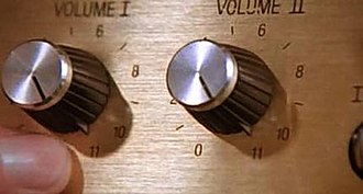
I get what you're saying....but this one goes to 11 :wink:

330px-Spinal_Tap_-_Up_to_Eleven.jpg
 

Latest posts

Back
Top