WIP Under Stairs cupboards

UKworkshop.co.uk

Help Support UKworkshop.co.uk:

This site may earn a commission from merchant affiliate links, including eBay, Amazon, and others.

Stimpi

Established Member
Joined
8 Mar 2014
Messages
94
Reaction score
0
Location
East Sussex
Under Stairs cupboards. No live animals, rules or tapes were used during the making of this post.

This is a project I have been considering for some time to which I have now made a start.
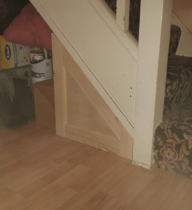
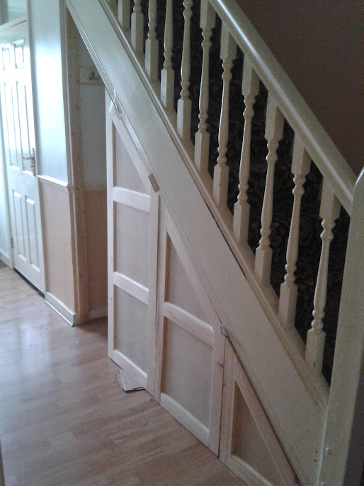
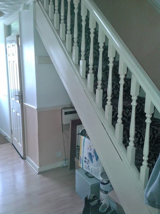
These are the stairs in question, quite normal, a straight flight with a quarter space landing top and
bottom.
1.+The+stair+as+original.jpg


It has been a rainy day project for some time now with me toying with ideas with how the design should go. The job is now a goer and with Sharpy86 showing an interest last April I need to be prepared for questions and plenty of pictures .
One factor always constant in my mind is it is on the top floor level of a block of London flats with no lift. Everything has to be humped up a load of stairs. Another factor is I can only get up to London one day a week which will affect progress.
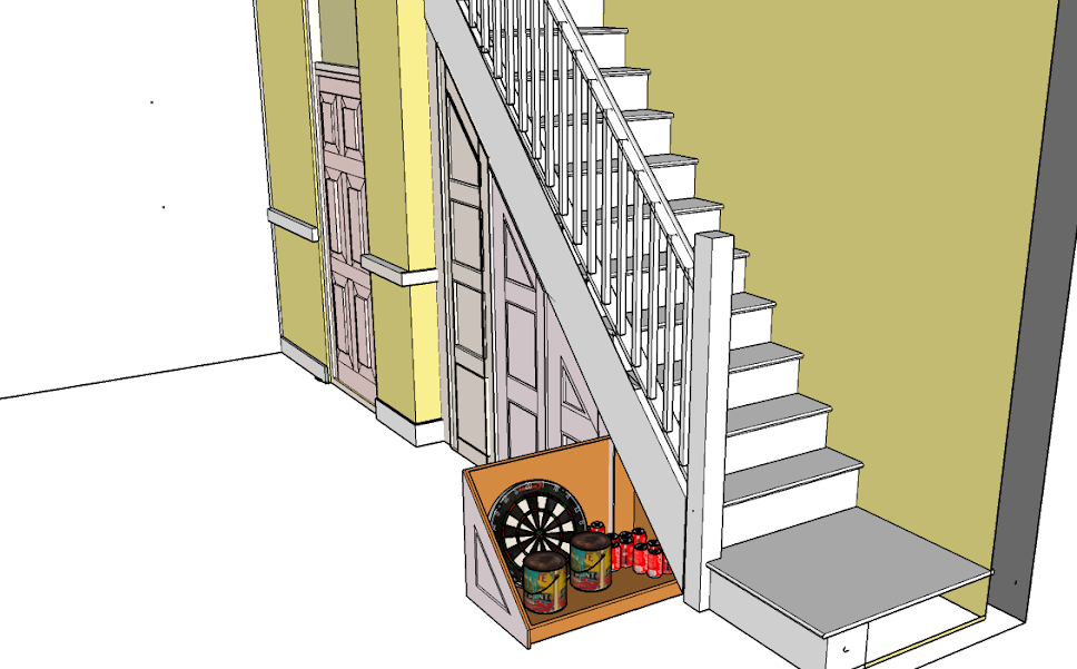
The way I wanted to go was constructing pull out cupboards on trolley wheels but the client did not want this with the and had a preference for a flush surface using MDF.
In the end it has come down to cost. Framed/paneled softwood is cheaper than MDF, easier to hump up stairs, I can transport it my self with own transport (£18.00 delivery charge on MDF), fabrication easier and I can fabricate at home in my own workshop. Still have to transport the gear to London.
So this is the plan
Riser.png


Staircase work is all about angles and work with angles is unforgiving, due to inaccuracies being exaggerated. Accuracy is the key which is why I prefer the use of Rods. Rules and tapes are left at home. Example, if I cut a joint 1/32”, out the discrepancy will grow just short of ¾ “ in a foot.

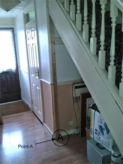
The first task was to secure a 3” x 1 ½” vertical post plumb in both directions on the face at the high point of the spandrel. This is my reference in producing a rod. I call this reference point A
Point+A.jpg


Reference Points for the rod. That is, physical marks are made between the reference point A and the newel Reference point B

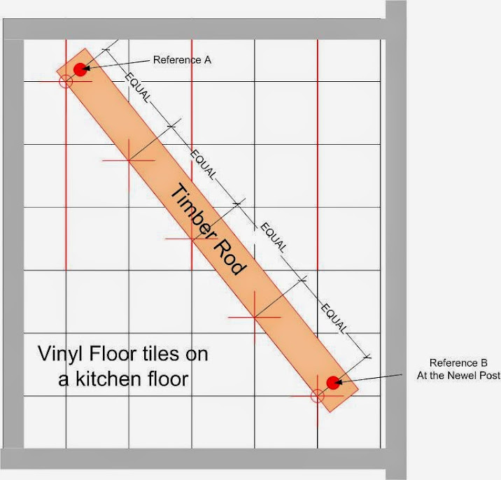
This then has to be divided equally into four. I did this using geometry on a flat surface.
The flat surface I used was the client’s kitchen floor which was covered with a grey vinyl tile.
I will try and illustrate the theory with sketches rather than photo’s and then try and explain what I did and, why it was a simple process even without the use of rules or tapes.
Kitchen+floor.jpg


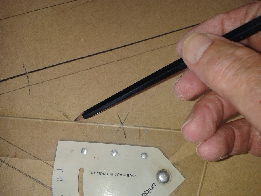
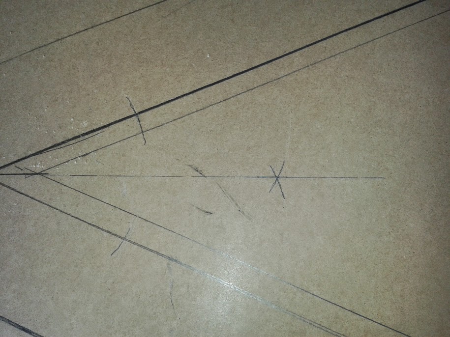
I selected eight tiles as the A – C line fist placing pencils and bits of wood as demarcation. Brought to it the Rod with its two reference points matching the A reference with the first demarcation pencil. And swinging the B reference to form the angle till it met the tile line.

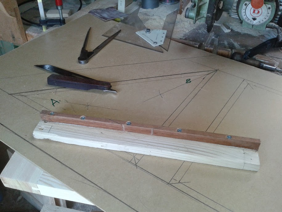
A useful piece of kit, easily made was used to check the spaces are equal which are, an overgrown pair of dividers. Useful for checking the divisions are equal.
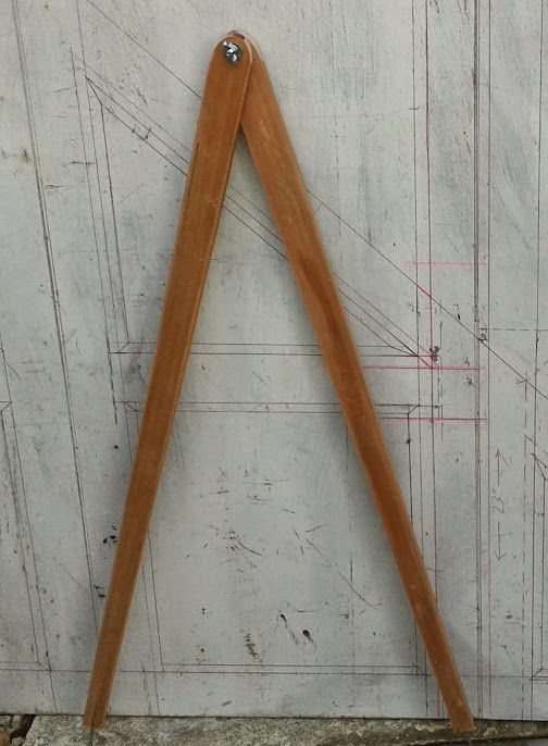
20140522_182012.jpg


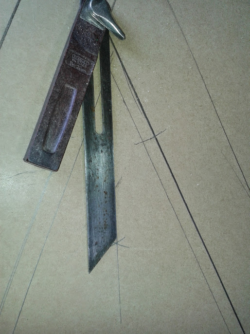
I then took this Rod to the stairs, lined up the reference points and transferred the divisions on to the floor.
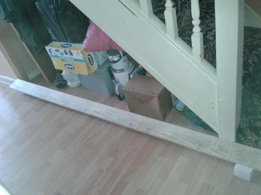
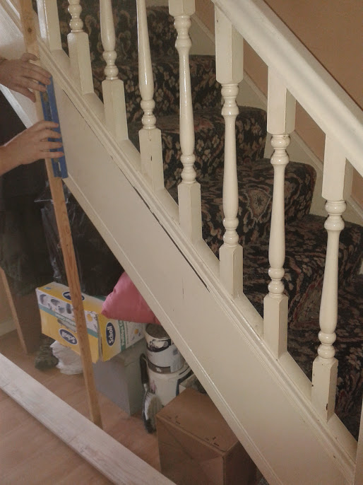
20140517_110007.jpg


20140517_110316.jpg


These marks were plumbed up and marked on the stair string plus marking the heights on a story Rod

20140517_110316.jpg


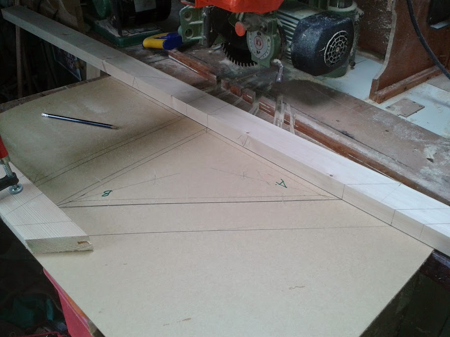
With this information I drew more detail into the Rod using short ends of material positioned either sides of the marks.
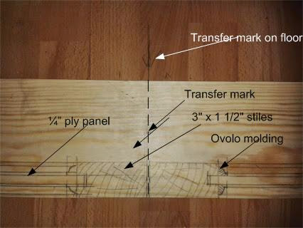
Transfer+Rod.jpg


With this information I drew more detail into the Rod using short ends of material positioned either sides of the marks.
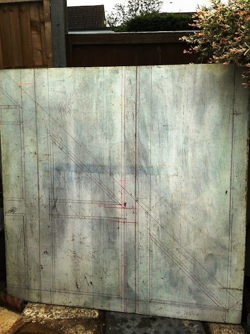
Layuot1.jpg


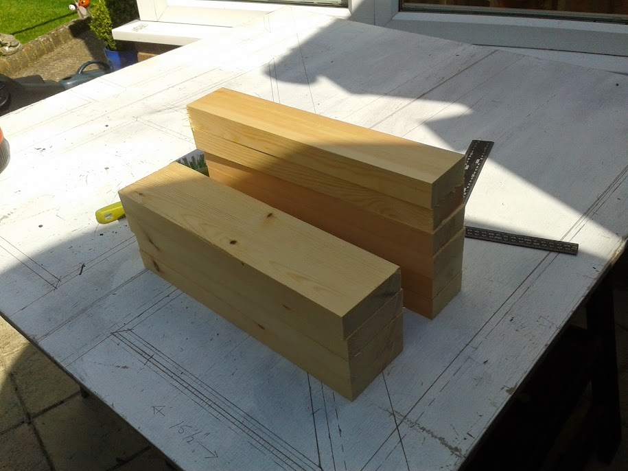
This was the setting out complete and cutting the stock to size began, gauging all like members to these Rods.
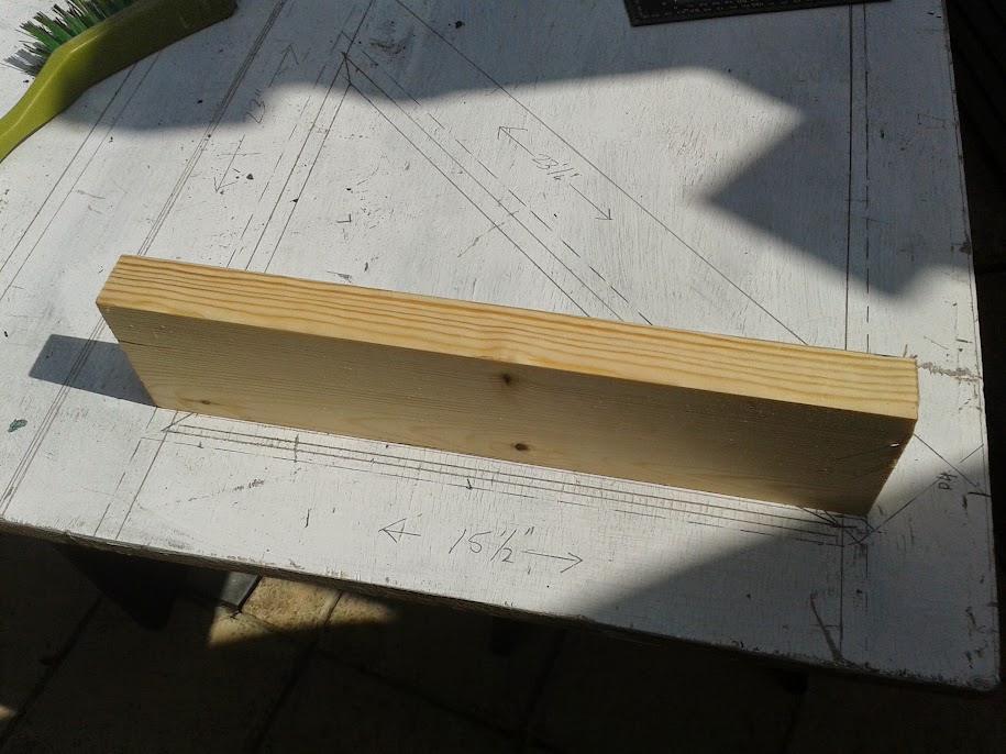
20140514_152520.jpg
 
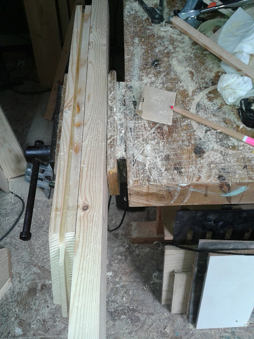
All the cross rails ready for making tongued and grooved joints

20140514_161421.jpg


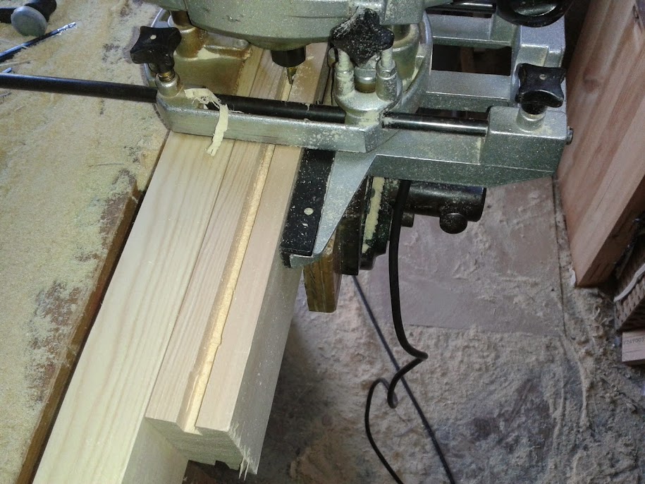
Forming the grooves with the router using, a ¼” bit. A tip is to use a second timber longer than the machined piece as a lead in for the router fence. After routing with the fence off one face turn the stock round and rout again, This ensures the groove is central.

20140520_163604.jpg


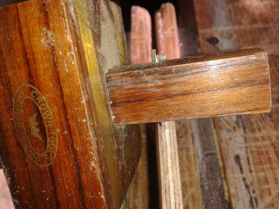
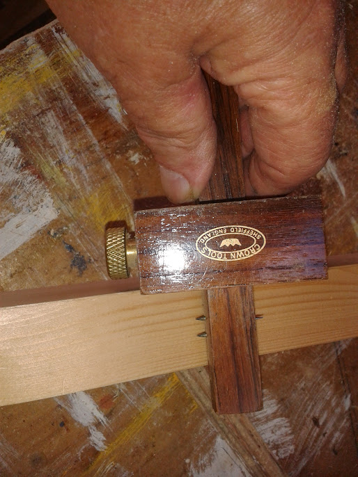
This is a one off setting for the fence and care was taken in setting it. First I set the thickness width of the ply with a mortice gauge.

Forming+grooves.jpg


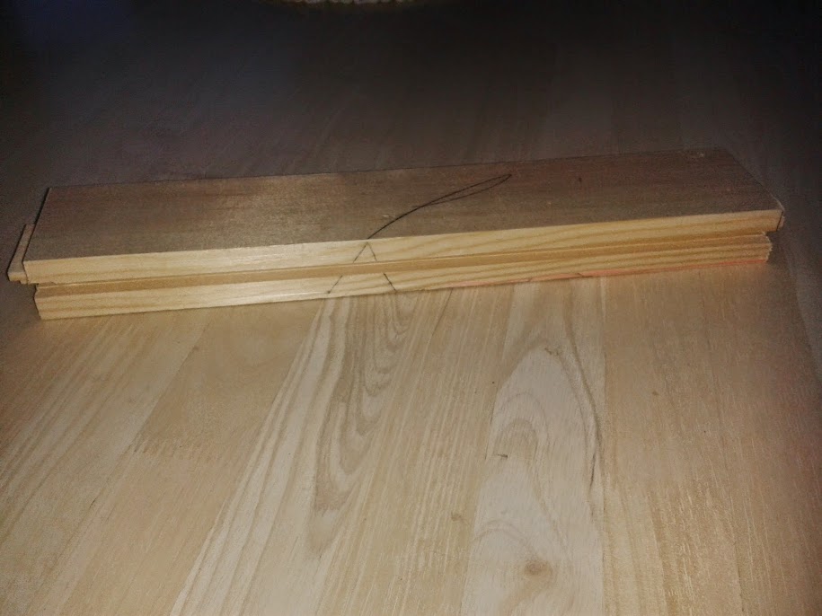
Set the gauge to register central in the width by from one face, pricking it turn it round and prick again and adjust. When the prong holes match tighten the screw and we are set to go but, not after the face sides and face edges have been selected and marked.

20140514_164146.jpg


20140514_164229.jpg


Its good housekeeping and it lends itself to accuracy which for angle work is what we are looking for. I cut my stub tenons on the RAS because I have one and the micro adjustment suits me. The table saw could be used but there is an issue with elf & safety due to removal of the riving knife and guard. Cutting by hand is always an option or even setting up a jig and using a router? There are 20 stub tenons to form which can be tedious.

Face+Marks.jpg


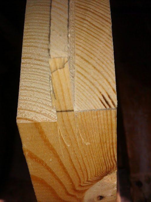
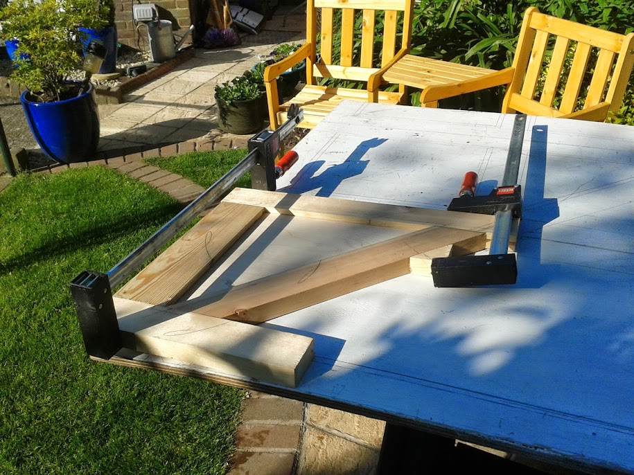
FIRST PROBLEM I cut all the 20 straight tenons no problem, it’s better to do all the cutting appertaining to one set up in one go as it is nigh impossible to reset exactly again second time. I set stops to form the diagonal cheek cuts and adjusted the angle of the RAS accordingly. First cut fine again no problems angles fine, cut on line. Re-set for the reverse angle, could I get it right? No I could not! I was using up would like it was going out of fashion. I couldn’t use short pieces due to Health and safety. Its dangerous putting short ends to an angled blade. I was running out of time and as I was due to go to London next day I was keen to get a glue up and try out my first panel for fit. So I reverted to doing the two offending cuts by hand.
This is the worse one of my attempts. The micro adjustment for horizontal angles on the RAS is non existent. I am going to have to think this one out for the next three top rails.

20140515_153938.jpg


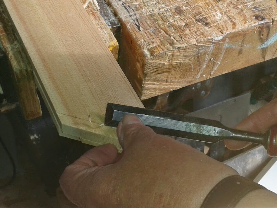
Tip for cutting tenon shoulders is to knife the line and cut a v with a chisel but when the shouder is on an angle cut against the grain.

20140515_155035-1.jpg


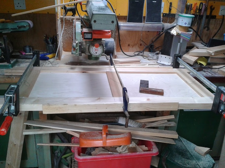
I cut a ply panel for the infill and achieved my target for the glue up.

The+Glue+up.jpg


This did not go as sweet as I would have liked. I ended up with screwing a block cut at the correct angle. This is something else I would have to think about.


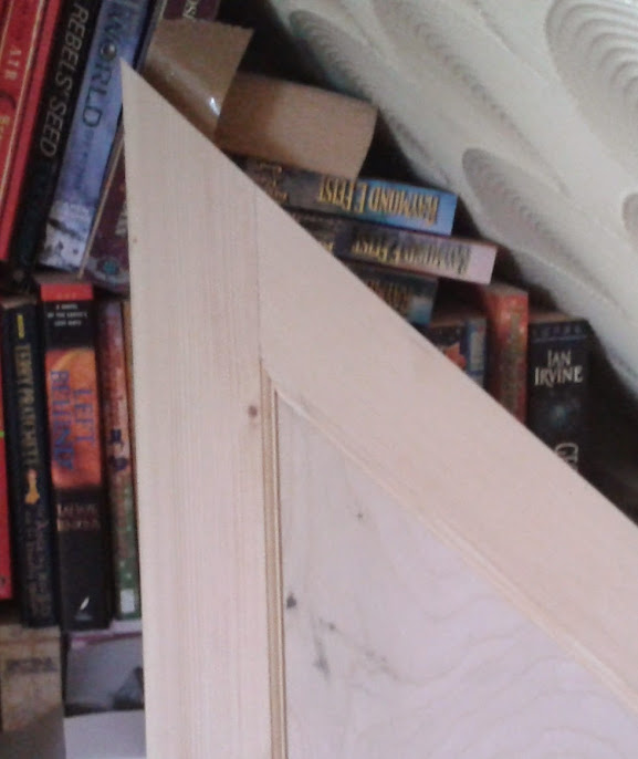
After the glue has set, the clean up and then the fitting of the ovolo beading. The mitres to the top angles require a special mitre block the angles being set with more geometry.

20140516_145955.jpg


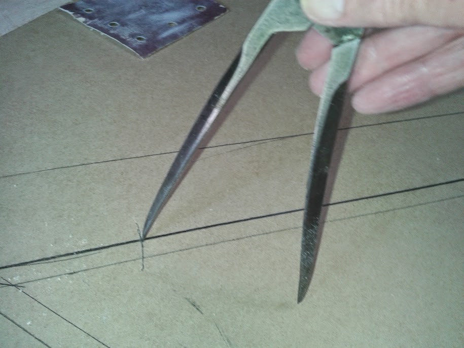
Mark any distance up the sides of the angle

20140516_142137.jpg


20140516_142000.jpg


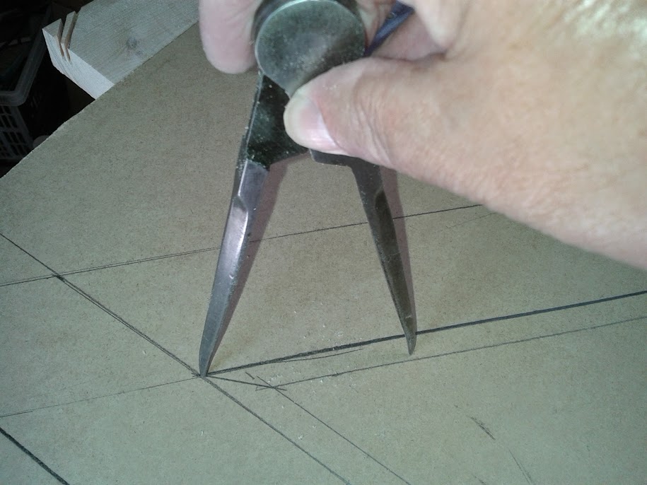
Form arcs from these marks


Join the arcs and the corner together
20140516_142300.jpg

The required angle
20140516_142407.jpg

Set the bevel to match
20140516_142537.jpg

Make a mitre block

20140516_143718.jpg


All set for the trip to London tomorrow

20140516_145955.jpg


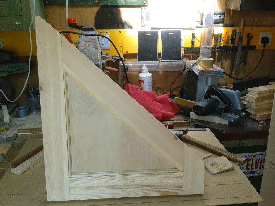
Not perfect, close inspection of the top left joint is grinning slightly I have to think about the cramping procedures with regard to that block positioning. This discrepancy resulted in the bottom rail being out of square and thereby not fitting to the angle. A bit of planing cured this and the
panel now fits OK. One down three to go.

20140516_191637-1.jpg
 
Always interesting to see someone else's workflow. Don't really understand the aversion to tape measures - I'm all for story sticks etc... but using someone's floor tiles to mark out the panel widths seems bizarre to me - I'd just measure it and divide by four, personally.

Must confess to being a bit confuddled by what it is you're actually building - are they still pull-out cupboards, just with a panelled front, rather than the flush front you say the customer preferred? Either way, that panel seems a very snug fit - unless I've got the wrong end of it and it's a fixed panel, surely it'll bind if it's that snug?

As I say, always interesting to see other people's approach, and thanks for posting yours.

Cheers, Pete
 
Good points Pete, you must have noted a hint of cheekiness in my thread. We have all heard the adage "measure twice cut once" The boss said "You got it wrong again Mike. Did you measure twice?. Yes I says. Well what went wrong?. I measured it wrong. Then stop measuring or stop cutting your costing me a fortune!
A bit of fiction. The point I am making is for some work particularly staircase work accuracy is King. The joint where I had a slight difference measured say a 1/16th that's a growth rate of 3/16ths in a foot, Over the length of the string that an inch an a quarter. I used the tile floor because it was there and the results were spot on. The actual length is as dammit is to swearing six feet seven and a half or is it six foot seven and nine sixteenths? does it matter? In metric its 2.02 or is that 2.019? Divided by 4 is 0.505 there could have been more decimal places or even a reoccurring number but this is the point. Quicker than searching for my tape, measuring twice, swapping glasses to make sure I have read it correctly finding a scrap of wood or paper and pencil to write it down, searching for the calculator or phone to work out the division, is the battery charged? doing a long division sum I have the EXACT distance (don't know what it is but it's correct) and enjoying a nice cup of tea. If the tiled floor was not available I would have used the garage floor and drawn the A B line first and then the A C line. By the way this is how the stone masons of the middle ages set out there projects, on a clay floor.

Regards Mike B
 
Hey Mike.

Stimpi":1diw5sh2 said:
The point I am making is for some work particularly staircase work accuracy is King.
Don't disagree - I'd template each panel, personally, but as I said, interesting to see how others approach it...

The actual length is as dammit is to swearing six feet seven and a half or is it six foot seven and nine sixteenths? does it matter? In metric its 2.02 or is that 2.019? Divided by 4 is 0.505 there could have been more decimal places or even a reoccurring number but this is the point.
OK, but I think the point is that if you're designing, fabricating and fitting the piece, then they can be whatever measurement you choose. As you say, 2020mm divided by 4 makes for 505mm panels; but if it's 2019mm, then 3# 505mm panels and a 504mm panel will also do the job. I work for some very pernickety customers, and I would defy any of them to spot a 1mm difference in panel width.

By the way this is how the stone masons of the middle ages set out there projects, on a clay floor.
There's a lot to be said for the old methods, and I frequently draw out projects at full size myself. But there's also a lot to be said for modern, accurate tape measures, too e.g. Talmeter. Not saying I'm right and you're wrong, just different approaches, and I appreciate you posting yours.

Cheers, Pete.

Edited for clarity.
 
An easy way to glue up the bevelled tops is to either glue two doors together, out of long stiles, upside down to each other, as the bevels oppose (there is less squaring up required also!) or a more wasteful method is to extend the stiles longer and have a rail the correct width to clamp on, then wedge/clamp from this to hold the diagonal.

Keep up e good thread though!
 
An easy way to glue up the bevelled tops is to either glue two doors together,

Brilliant! I never thought of that, Thanks for the tip I am on the last after a session in the Big City last night just got back and first job see if any posts, there was and you made my day.

There's a lot to be said for the old methods,

Your correct Pete, I am not averse to measurement I earn my living as a surveyor, the tools of my trade are tapes, measuring rods, levels, theodolites etc. Joinery is a hobby which I enjoy, one point I want to stress. I required to construct four doors of the same width, this required machining nine cross rails to exactly the same length, four tricky diagonal top rail, again exactly identical including setting the stops on the RAS.
Measurement can have issues. Using geometry is exact, simple and effective. I did have problems in altering the second cut on the shouders which was resolved but, wasn't a measurement problem it was a use of machine problem.
Time to process the pictures from the latest visit.

Regards
Mike B
 
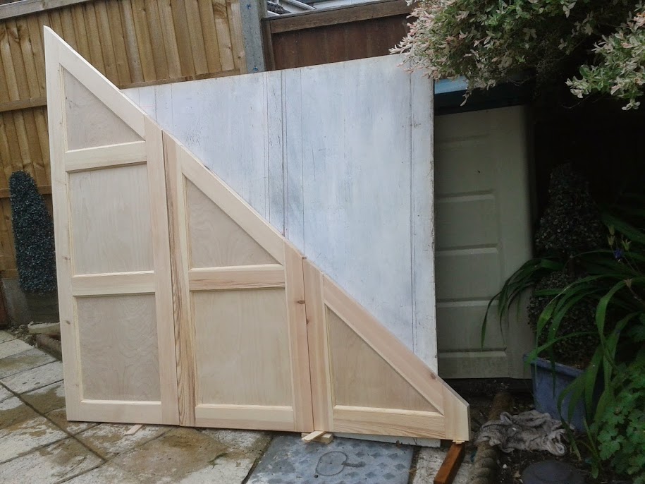
Three down one to go. Just think If I had thought of Olly’s tip it would be Four down. Now, let’s have a hanging!

Three+down+one+to+go.jpg


Joints still OK

Third+joint+inspection1.jpg


In position

Third+door+in+place.jpg
 
Thanks for the interest Woodmonkey. Work will be delayed this week due to looking after Grandchildren while my siblings do real work.
 
awesome, keep the posts coming, i really want to do this in my new home, but have draws to pull out.

id really like to know what runners you will / would use for the draws etc

do you plan to hide any handles? if so how?

i thought about removing some handle shapes from the top of the faces but i think it would ruin the look, i suppose some kind of push in pop out solution would work but i dont know how well with big heavy draws.
 
Stimpi this is looking really good - thanks for posting.

This is looking a lot more technical than my project so far - which isn't suprising!

I'm making mine out of MDF sheets, and have so far made the carcases (3 of them). I will then fit a shaker style front on each drawer (a bit like how a kitchen drawer is made). The shaker style is going to be created by gluing 6mm MDF borders onto a 12mm front - I know its cheating, but rails and floating panels are well out of my skillset!
 
I don't have one at the moment, no.

However, if people are interested, I have taken a few photos that I could share.

I'm 'working' from home tomorrow, so will have the perfect opportunity to put something together.
 
However, if people are interested, I have taken a few photos that I could share.

Of course I or we are interested. Does the Pope have a balcony?

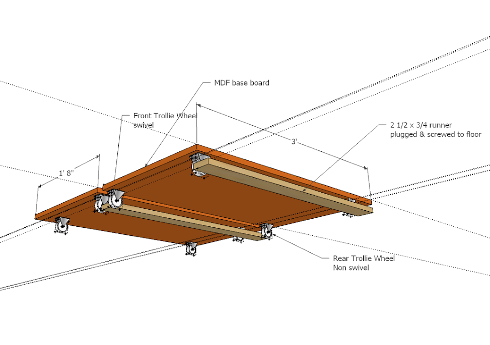
If you are using MDF you will not be required to have each door exactly the same width. My client is still insistent on not having pull out drawers. I think is a mistake, a much better use of the area. My intention was to use swivel wheels on the front and non swivel on the back. Position them and then fix 2 x 1 rails to the floor butting on the out side of the wheels. For handles brass flush handles let into a rail.

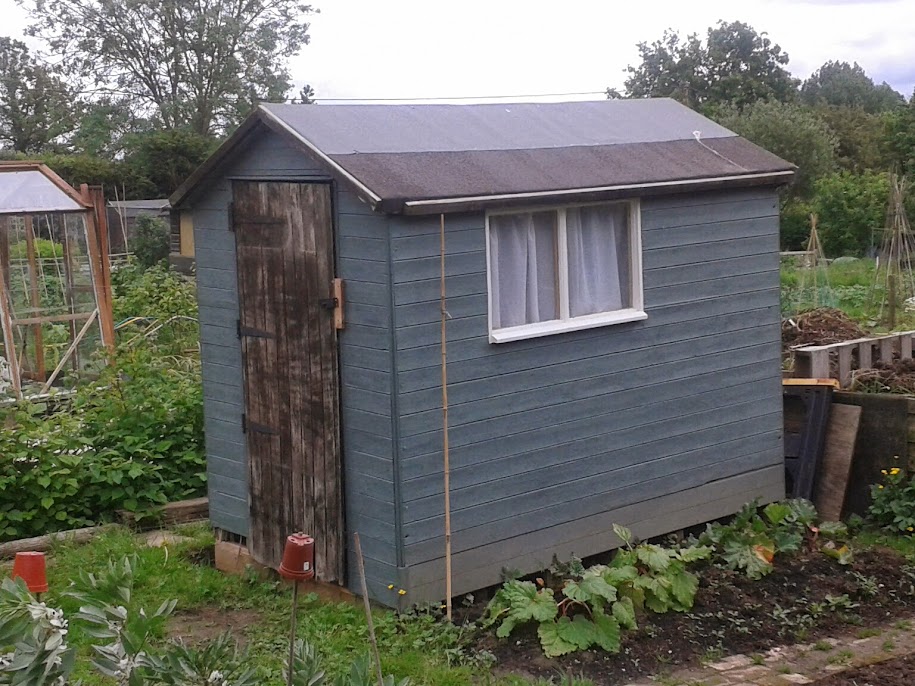
As previous post no work this week due to half term though did manage to do some more work on the allotment shed using reclaimed panels from this years storms. Still have a door to make kids had a great time at the allotment exploring the nearby woods.

Nearly+finished.jpg


Cheers
Mike B
 
Have been thinking how to form the base and wheels.

Base+board.png


The front wheels wold swivel while the back ones are ridged. The floor batten at the Newel could be 1 1/2" x 3/4" and at point A

Regards
Mike B
 
would it not be as good to use some heavy duty draw runners?

or were you intending to have them run along the floor?
 

Latest posts

Back
Top