Spot the oversight

UKworkshop.co.uk

Help Support UKworkshop.co.uk:

This site may earn a commission from merchant affiliate links, including eBay, Amazon, and others.

RogerS

Established Member
Joined
20 Feb 2004
Messages
17,921
Reaction score
276
Location
In the eternally wet North
In another thread, I talked about how I went about getting some custom spindle moulder cutters made. But I cocked up. Can you see where ? PM me if you can.

To recap

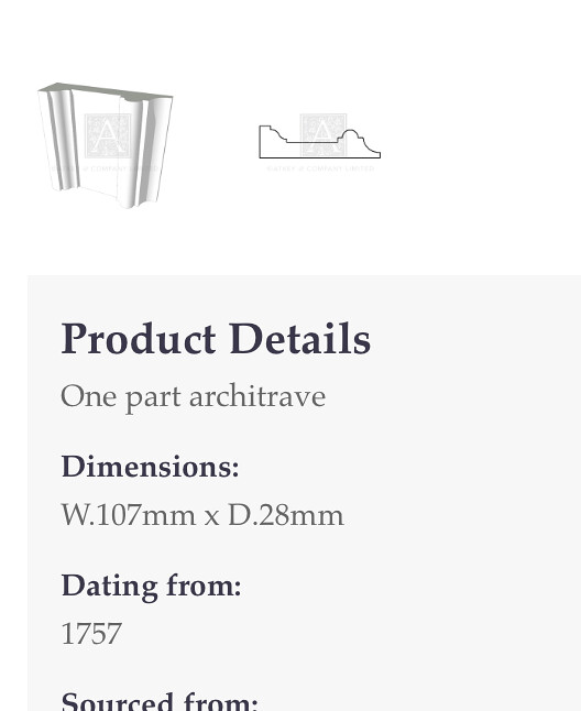
This is the architrave I wished to make


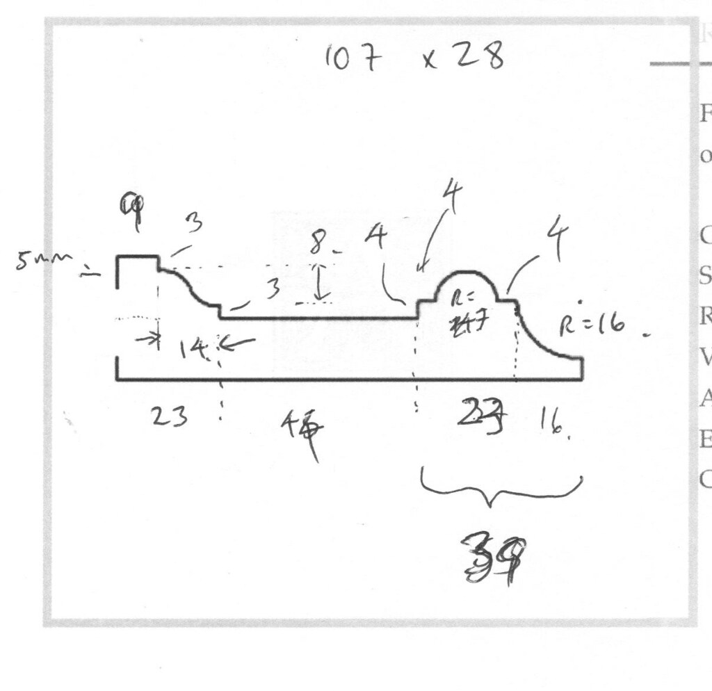
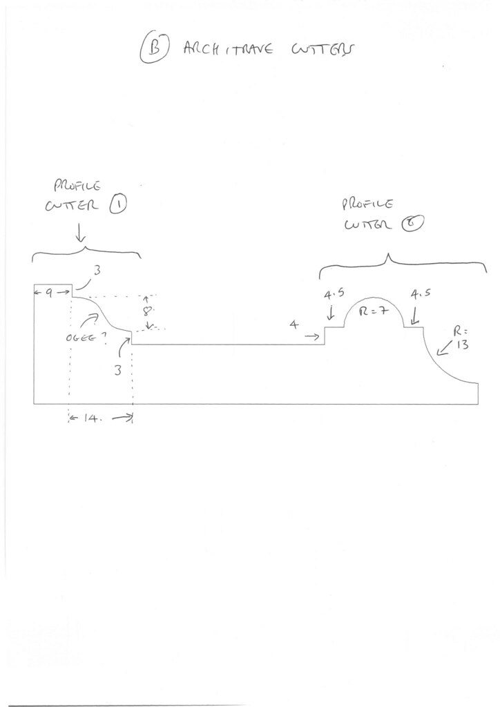
My working drawing


Tarted up and submitted to Whitehill


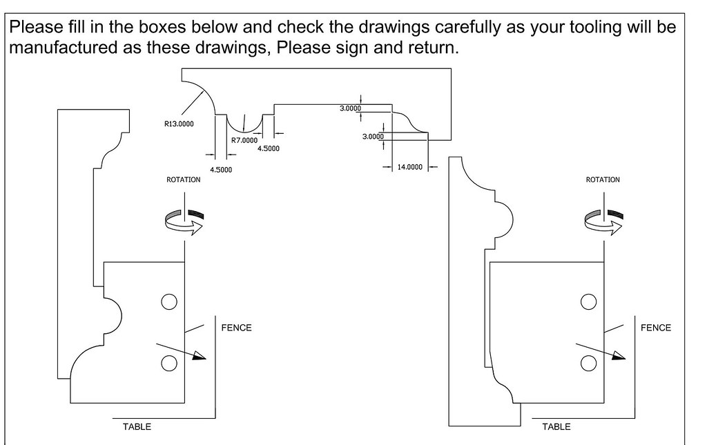
Draft cutter schematic from Whitehill


I then suggested that they could extend the cutters (shown shaded) to avoid me having to make a third pass with a rebate cutter
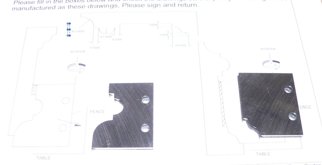


Second draft
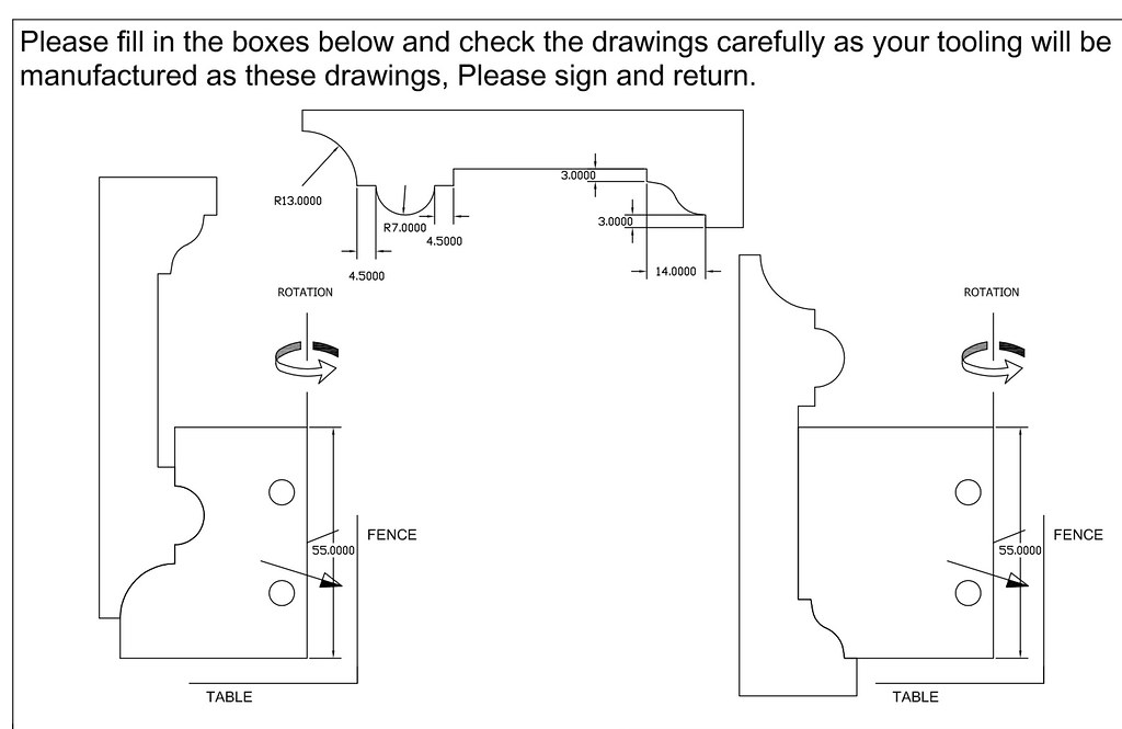


They missed one !

Final signed off cutter drawing
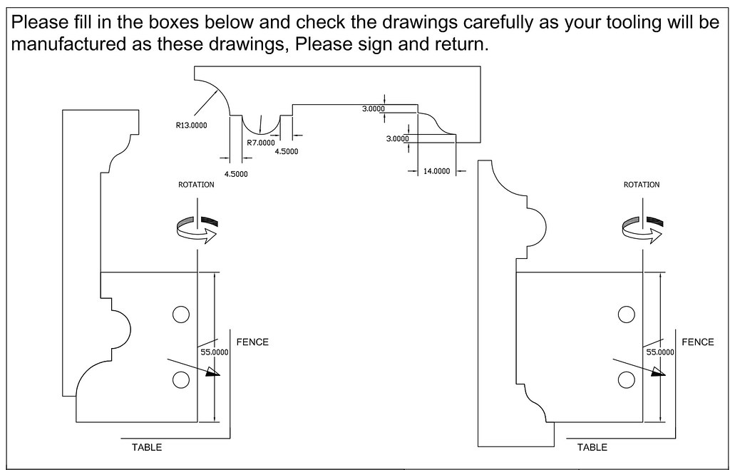


Neither they nor I spotted the oversight aka ****-up which didn't become apparent until I'd finished moulding two sets of architrave :(

Can you spot it ? As I said, PM me if you can.

Not a complete disaster and not that obvious on the finished product and I doubt that anyone would notice it. It's easily fixable for the remaining 12 sets.
 
Is there a cutting edge ground on the top of the LH cutter.

Personally, I would say it would be very difficult to avoid a step where the 2 cutters form different parts of the rebate. Once the first cut is done there is a real liklehood of the timber cupping.
 
The dim defining the 8mm "depth" of the ogee seems to have got lost in the process?
Cheers, W2S

PS the lower 'quirk' on the ogee is 3mm and the corresponding dim (which also got lost off) at the other side is 4mm ! ahaaa the two parts of the rebate will be 1mm different depths?
 
The cutter with the half round requires the piece to float above the table as you cut it in their pic, so I’m guessing the profile became a bit elongated?
 
RobinBHM":qasa35du said:
Is there a cutting edge ground on the top of the LH cutter.

Yes there is
RobinBHM":qasa35du said:
Personally, I would say it would be very difficult to avoid a step where the 2 cutters form different parts of the rebate. Once the first cut is done there is a real liklehood of the timber cupping.

You're bang on the money there re cupping as I found out the next morning ! LOL...

In reality the step (albeit very slight even fading to nothing at times) is not where you think it will be....

There's a clue
 
Woody2Shoes":uqq898m9 said:
The dim defining the 8mm "depth" of the ogee seems to have got lost in the process?
Cheers, W2S

That's true..I'd not noticed that although it doesn't seem to have affected things TBH.

Woody2Shoes":uqq898m9 said:
PS the lower 'quirk' on the ogee is 3mm and the corresponding dim (which also got lost off) at the other side is 4mm ! ahaaa the two parts of the rebate will be 1mm different depths?

No they won't be because in the original moulding the profiles between left hand and righthand side are different (bit difficult to explain).
 
--Tom--":2of0r8n4 said:
The cutter with the half round requires the piece to float above the table as you cut it in their pic, so I’m guessing the profile became a bit elongated?

No, you just lower the spindle to bring the cutter down to the right level ...
 
RogerS":hnfl4a4e said:
Woody2Shoes":hnfl4a4e said:
The dim defining the 8mm "depth" of the ogee seems to have got lost in the process?
Cheers, W2S

That's true..I'd not noticed that although it doesn't seem to have affected things TBH.

Woody2Shoes":hnfl4a4e said:
PS the lower 'quirk' on the ogee is 3mm and the corresponding dim (which also got lost off) at the other side is 4mm ! ahaaa the two parts of the rebate will be 1mm different depths?

No they won't be because in the original moulding the profiles between left hand and righthand side are different in relative height to each other (bit difficult to explain).

And that difference turned into right old BA ...I had to come up with a solution for that...

..supplementary question..why was it an awkward sod to do ?
 
RobinBHM":2jjyqxys said:
Is there a cutting edge ground on the top of the LH cutter.

Personally, I would say it would be very difficult to avoid a step where the 2 cutters form different parts of the rebate. Once the first cut is done there is a real liklehood of the timber cupping.

I'm struggling to get my head round what causes this effect - Roger's clearly confirmed that it happens(!), but what causes it? Is the cupping expected to be towards the cut face (what I would expect, based on a pure guess) or away from it? What rule(s) should be followed to avoid this (always cut a whole profile in one pass, or...)?
Cheers, W2S
 
RogerS" And that difference turned into right old BA ...I had to come up with a solution for that... ..supplementary question..why was it an awkward sod to do ?[/quote said:
I guess because the rebate is the only place where the second cutter is cutting (part of) a face that already had been cut by the first cutter (to the "correct" shape) in this situation I guess tiny variations are inevitable and there will be some "uneveness" in the rebate after the second cut.

The solution? Make a third pass, with a rebate cutter, or a shoulder plane, to clean up the rebate? Radius the corners of the two cutters? Erm...
 
Woody2Shoes":206mltmc said:
RogerS" And that difference turned into right old BA ...I had to come up with a solution for that... ..supplementary question..why was it an awkward sod to do ?[/quote:206mltmc said:
I guess because the rebate is the only place where the second cutter is cutting (part of) a face that already had been cut by the first cutter (to the "correct" shape) in this situation I guess tiny variations are inevitable and there will be some "uneveness" in the rebate after the second cut.

See my response to Robin...it's not the BA, by the way :D
 
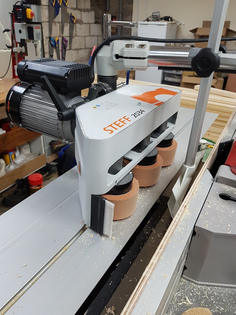
If I was attempting that on a router table, I'd be kicking myself because it would need an aux. fence (3mm) above the cutter for the 2nd pass, so the half-round could run on it. Bad enough doing that manually, but I'd guess quite tricky with a power feed - it will wear your newly cut profile and won't like a lot of pressure.

On a router table, I'd be tempted to cut the profile on a wider bit of stock, then bandsaw the back to get the overall thickness. Can you do that with a spindle moulder, and does it help at all?
 
If your not doing it with two blocks stacked, having thought about it the direction of rotation would be best reversed for one of the cutters to allow the spindle to be reversed and the both cuts made in the same direction to prevent tear out as the cuts will be in opposite directions at the moment.
 
deema":sa18zlqc said:
If your not doing it with two blocks stacked, having thought about it the direction of rotation would be best reversed for one of the cutters to allow the spindle to be reversed and the both cuts made in the same direction to prevent tear out as the cuts will be in opposite directions at the moment.

Nice idea to use two blocks but my spindle's not long enough - would save a shedload of time. Having said that, I do have to turn the timber over and I've not had any tear.
 
Not sure if I missed something, but your initial sketch has the inside ovolo as a R16 that becomes R13 on subsequent drawings; consequently your inner moulding is 3mm narrower and the flat central part 3mm wider.

Looks like a good service from Whitehill.

Cheers

[PS Couldn’t you just grind them yourself :idea: :?: ]
 
PS I would be interested to know what your setup on the spindle moulder is. I assume you have a power feed (they are both pretty substantial cuts).

Do you have some support on the outfeed side to keep the workpiece straight and upright?

Cheers
 
scholar":1skcxf6a said:
Not sure if I missed something, but your initial sketch has the inside ovolo as a R16 that becomes R13 on subsequent drawings; consequently your inner moulding is 3mm narrower and the flat central part 3mm wider.

Looks like a good service from Whitehill.

Cheers

[PS Couldn’t you just grind them yourself :idea: :?: ]

Good spot but that change was deliberate after seeing the result of the SketchUp drawing. But your reference to the flat central part is definitely in the right neck of the woods !

Make my own ? Not a chance!
 
scholar":28rytk3b said:
PS I would be interested to know what your setup on the spindle moulder is. I assume you have a power feed (they are both pretty substantial cuts).

Do you have some support on the outfeed side to keep the workpiece straight and upright?

Cheers

Bang on the money, there. A decent powerfeeder


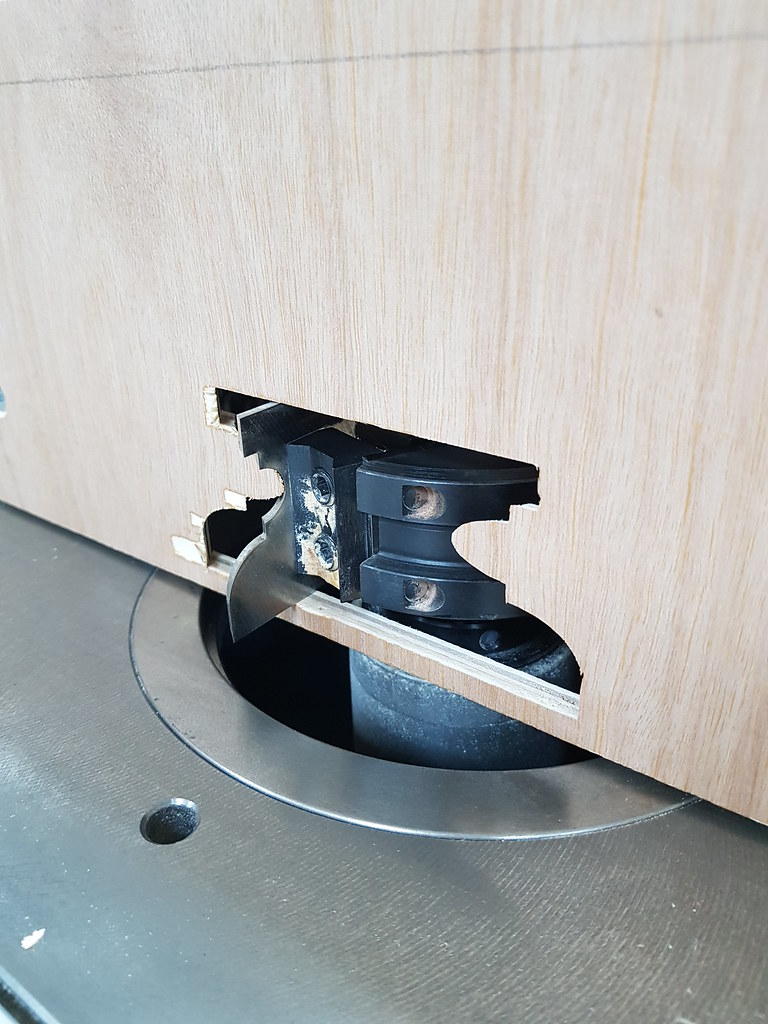
A good false (aka sacrificial) fence like this


And a 2 metre aluminium channel on the outfeed to support the stock.
 
I’m stumped then. It all looks fine to me!!

I am puzzled and now really need to know the answer to this brain teaser.

My question re outfeed support was thinking whether you needed some support against the fence for the previously machined part (basically the point raised earlier by @eric the viking)

Cheers
 
Back
Top