Fixing up an old lathe

UKworkshop.co.uk

Help Support UKworkshop.co.uk:

This site may earn a commission from merchant affiliate links, including eBay, Amazon, and others.

threeReefs

Established Member
Joined
25 Feb 2019
Messages
21
Reaction score
6
Location
Guildford, Surrey
So I went and bought an old lathe.

Something I have been meaning to do for a while, to satisfy the longing not so much for turning metal (although obviously that's in there somewhere) as for restoring some old iron and learning about it.

I had originally thought of something like a Colchester (Bantam, Student, that sort of thing) but eventually realised this was really too much lathe for my first encounter, and I should start with something simpler.

I eventually went for this South Bend 9-inch (thanks to Tom/TFrench for helping with transport...) :
SB-crop.png


It's a 1943 lathe, and by all accounts has sat in someone's workshop untouched for a decade or two - the amount of dust and grime bears this out although there's no rust in sight - the previous owner clearly never fully cleaned it, but lavished copious amounts of oil on every visible part, which is hopefully a good sign. The headstock has barely-measurable runout, and the ways look pretty good. There is loads of backlash in the crossfeed and compound, but I reckon that should be fixable. Also a lot of back-and-forth play when I engage the half-nuts on the leadscrew, but since there's the same amount of play up near the chuck, and down near the tailstock, I figure it's the half-nuts which are worn, and not the leadscrew so much - and I can replace those. So, I'm giving it a cautious 7/10 so far, we'll see how we do.

First, all the stuff that came with it. not what you'd call a well-ordered kit of parts, but some interesting ones :
SB-Tooling.jpg


I can see

  • - three milling attachments (one not in the pic I've taken away for cleaning)
    - A dinky 4-jaw chuck and two 3-jaws, Pratt-Burnerd
    - A box full of HSS tools
    - A steady (looks home made :) )
    - Good collection of backplates
    - Nice set of rivett collets, with holder and two drawbars
    - A strange thing that looks vaguely like an indexer, but isn't - centre pic - any ideas ?
    - What looks like a turret thing, seems overkill for a lathe this size but anyway.
    - A very battered chuck and some centres.
Here's the thing-I-can't-identify : suggestions welcome !
SB-Mystery.jpg


Turret attachment, I think - probably surplus to requirements...
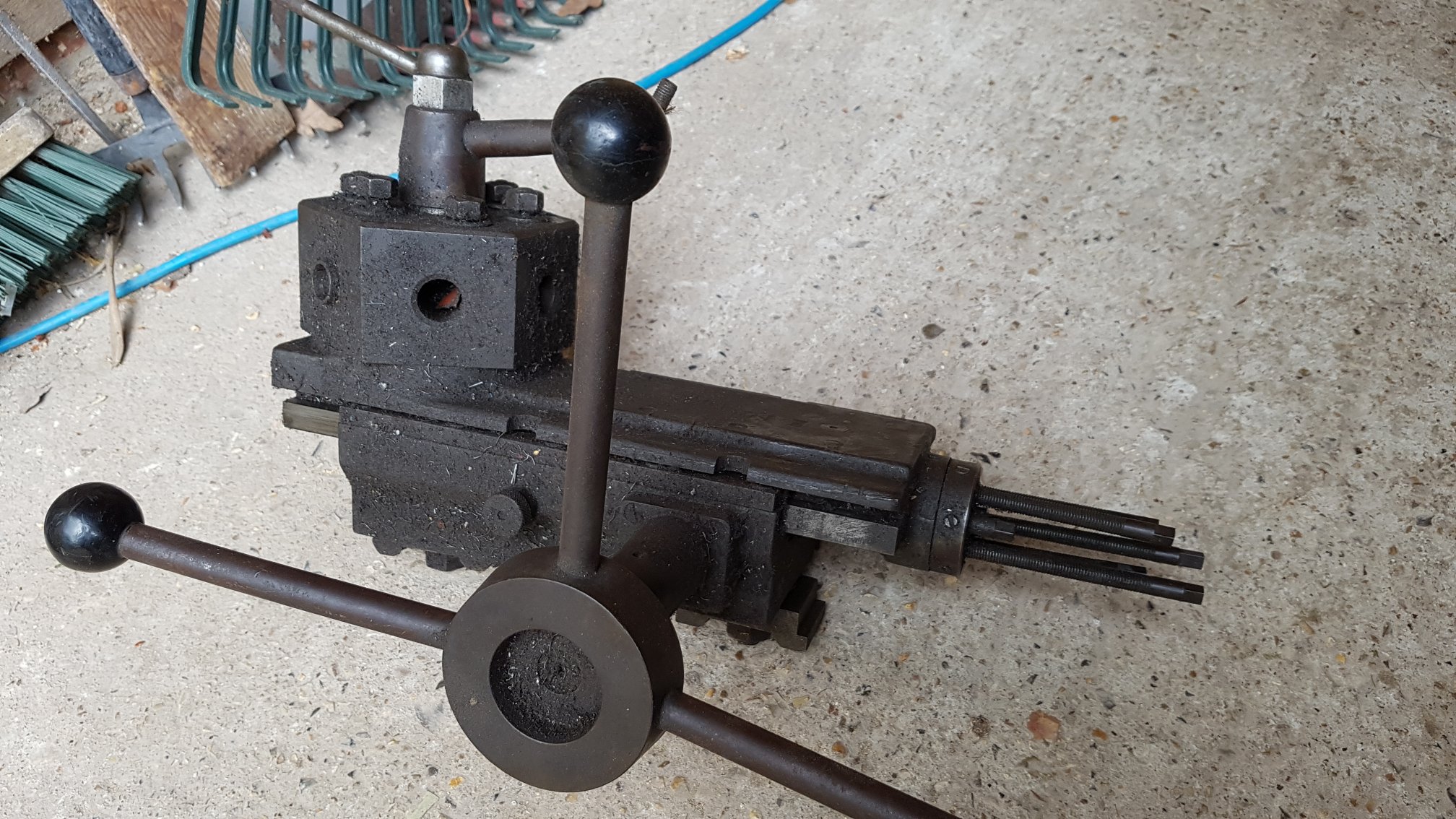
SB-Turret.jpg


There are two other crates of miscellaneous stuff, mostly strange brackets, tools, gears, and things that look like half-finished attempts to fabricate brackets to hold odd-shaped pieces of work. Haven't even tried to make sense of those, yet.

I cannot believe the size of the motor that came with this thing :
SB-Motor.jpg


Fricking huge and weighs 45kgs (getting on for 100lbs in old money). This came attached to a weird hydraulic speed-change device - I'll post a pic later. The previous user was apparently someone who ran an engineering shop professionally and this was his "home" lathe, so he's clearly experimented quite a bit. Tom will back me up that the motor+hydraulic drive came bolted together and were a pig to manhandle. But the motor is just 1hp ! And my favourite hand-held Hitachi circular saw is 2.5hp, with a motor the size of a tin of beans. I know the duty cycles are different, but even so. I'm gonna have to look into the motor/drive thing.

Initial exploration suggests things are incredibly grimy, chock full of swarf and cruft, so it's going to be an interesting cleanup. I will post some more pics as I go along, but I'm gently optimistic about enjoying the process, and ending up with something that works.
SB-Apron-Cruft.jpg
 

Attachments

  • SB-crop.png
    SB-crop.png
    1.2 MB
  • SB-Tooling.jpg
    SB-Tooling.jpg
    593.1 KB
  • SB-Mystery.jpg
    SB-Mystery.jpg
    390.1 KB
  • SB-Motor.jpg
    SB-Motor.jpg
    425.7 KB
  • SB-Apron-Cruft.jpg
    SB-Apron-Cruft.jpg
    374.5 KB
  • SB-Turret.jpg
    SB-Turret.jpg
    513.7 KB
Dont confuse HP with torque. Your circular saw will bind and stop in wood if it gets a bit tight, that motor will smash the wood to bits, light it on fire and feed it with the ghosts of mfi furniture. Completely different beasts. HP is a function of speed and torque, try to use your circular saw at 200 rpm then compare it again. :lol:

Still a cracking purchase you have there and lots of fun times ahead of you with your restoration.
 
Nice one!
I expect you know this, but MrPete222 (aka Tubal Cain) has quite a few detailed videos about South Bend lathes, I think including your model.
 
I think the unidentified doo-dad in the middle picture may be a radius turning attachment, used for the forming of balls, hemispherical recesses and similar, used by removing the topslide, putting the doo-dad in it's place with a toolpost or 4-tool turret on top, and radius set by the cross-slide. Then spin the workpiece, bring the saddle up to put on a cut, swing round by the handle so it turns about the vertical axis, and hey-presto a perfect ball-end on the bar end. The thingy stuck out of the side looks like an adjustable stop for the forming of partial ball ends.

There are quite a few 'make it yourself' designs and at least one commercial kit (Hemingway Kits) for small lathe radius attachments, but factory-made ones are as rare as hen's teeth. That one looks like a factory accessory, so nice find!

(PS - I bet you know this anyway, but the two vertical milling slides in the middle picture look like Myford accessories. If you don't have a use for them, they may fetch a useful bob or two on the 'bay or whereever.)
 
Hadnt noticed the "whata this bit" question. Yes it a sphere cutting plate. Yes its rare has hens teeth. The stop is mearly there to set a centre, dont to to swing past and ruin ypur cut by hitting the back of the tool. To use it you turn a shaft down to as small as you dare (depends on the size of the ball, i could look it up but the books in Nottingham) then take incremental cuts to turn a sphere. Good toy.

If you dont need the 2 vertical slides I'd happily take one of your hands for postage. :lol: kidding (put one on the bay, its worth a few bob).
 
I can definitely attest to that motor being a serious lump! Like the others said, I wouldn't be too quick to throw it away. The guy I picked it up from said the previous owner was an excellent engineer, and from the sound of it I don't think he'd have had rubbish. I would be tempted to just get it all cleaned up and bolted together and just see how it cuts. Make something basic and you'll quickly find what needs attention.
 
OK, several recommendations that I have a better look at that motor. So I did. I thought people might like to see the (initial) results.

First, let's check the electrical side of things. Whatever type of engineer the previous owner may have been, it wasn't 'electrical' :
melting_sm.jpg

Glad I didn't try just firing 'er up. But from the data plate this 44Kgs of metal draws nearly eight amps at the rated output.
nameplate_sm.jpg

That's quite a bit. And it's from a machine tool, right ? so I'm expecting an induction motor. And yet this is single-phase and there's no capacitor visible. And there are access plates on the side which look distinctly like they're for access to brushes. Series-wound maybe ? let's pop a plate and have a look inside :
peekinside_sm.jpg

Well, yes, a commutator, but it's not axial, it's in the plane of rotation of the rotor, and it's mounted in a frame which moves. Off comes the back :
back-off_sm.jpg

Those of you who know motors are probably way ahead of me at this point, but I had to do some digging to work out that this is a "Repulsion Start Induction" motor. It has windings on the rotor, and uses a commutator to short-out those windings at startup to provide starting torque without the need for a capacitor. As the rotor comes up to speed, a centrifugal clutch/governor - usually at the front of the motor - pulls the brushes away from the commutator, and the motor switches to running in full induction mode. So this thing is *way* more interesting and complex than I thought.

Off comes the front, let's see how they've done the centrifugal thing :
front-off_sm.jpg

front-clutch_sm.jpg

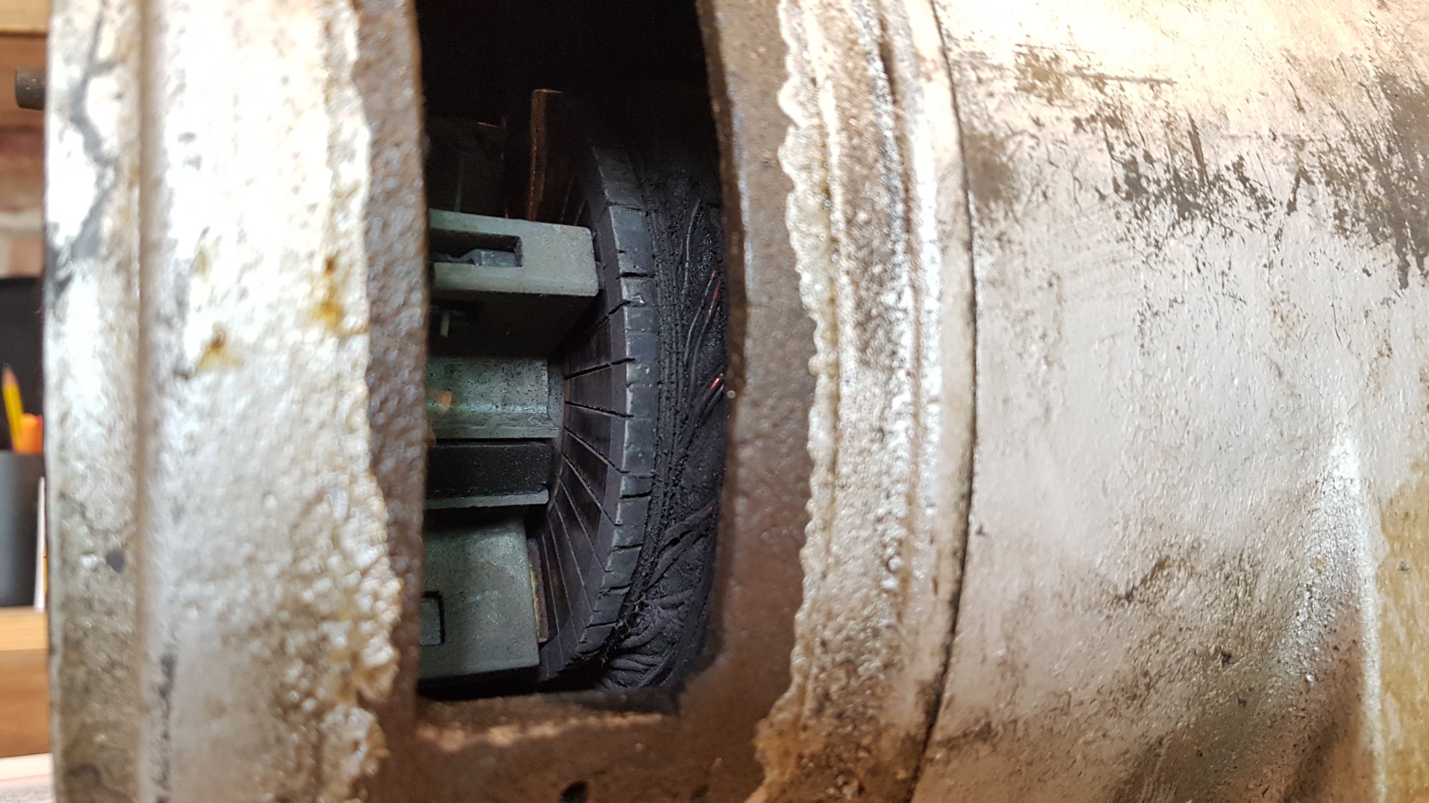
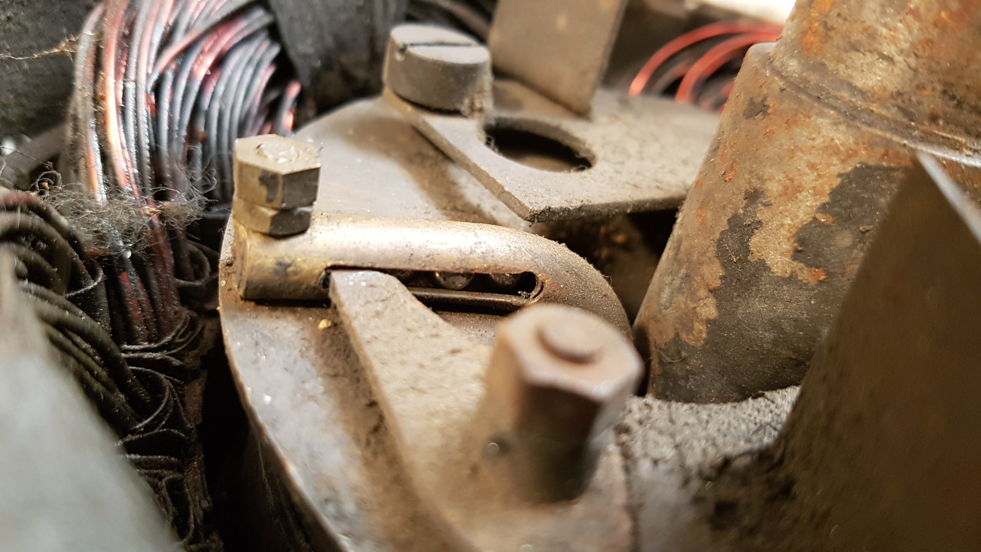
The large slotted screw at the bottom of the pic is the weight, and the plate pivots around the post with the two nuts on it. As the rotor spins faster, the finger on the end of the plate (which is slotted into the bent tube) pushes in towards the shaft. Now a very cool bit : this is motion 'across' the motor, and you need to convert this into motion 'along' the motor to drive a pushrod which runs right back through the rotor and disengages the commutator. How do you do this ? You use a string of ball bearings which you pack into the tube and which provide the 'flexible push' : as the finger pushes them, they trundle around the curve in the brass tube, and shoe the pushrod backwards.
bearings_sm.jpg

This is quite the neatest bit of engineering I've seen in a motor. And it gets even more complex : returning to the back of the motor, when you start removing the commutator sections, out pops an astonishing 'necklace' of copper segments which presumably also short-out the commutator segments when they're allowed to move backward :
necklace-both.png

Haven't quite worked out the exact purpose of these yet, but the motor is definitely interesting enough to spend some time cleaning up - if only for the fascination of watching it do its thing. And it might even turn out to be something that can drive the lathe. Out comes the rotor, finally : now that's a nice chunk of metal...
thatsarotor_sm.jpg

So, an interesting morning and I learned some things. As ever, it's what you learn doing this stuff that's every bit as good and satisfying as the end result. A couple of questions for helpful people out there :

- Any recommendations on substances for cleaning the windings ? they're covered in oily black crud, I'm not sure I want to use degreaser in there, kerosene possibly although I wouldn't want to leave anything remotely flammable in there either. Something that completely evaporates like acetone ?

- The bearings seem to have an OD of fractionally over 2 inches :
Bearing_sm.jpg

0.05 is too big to be an error, so probably not a 2-inch bearing ? That's 52.07mm - is that close enough to be a 52mm bearing ?

Anyway - thanks for all the comments everyone, I'll post some more stuff as I move along.
RT
 

Attachments

  • melting_sm.jpg
    melting_sm.jpg
    287.4 KB
  • nameplate_sm.jpg
    nameplate_sm.jpg
    544.2 KB
  • back-off_sm.jpg
    back-off_sm.jpg
    404.3 KB
  • necklace-both.png
    necklace-both.png
    1.2 MB
  • front-clutch_sm.jpg
    front-clutch_sm.jpg
    426.2 KB
  • front-off_sm.jpg
    front-off_sm.jpg
    403.6 KB
  • peekinside_sm.jpg
    peekinside_sm.jpg
    374.8 KB
  • bearings_sm.jpg
    bearings_sm.jpg
    336.4 KB
  • Bearing_sm.jpg
    Bearing_sm.jpg
    477.3 KB
  • thatsarotor_sm.jpg
    thatsarotor_sm.jpg
    444 KB
Nice buy. The radius arm is a great find. I wouldn't worry about the size of the motor compared to modern ones, they are just smaller now due to far better magnet materials. The motor on my 1930s Boley is 0.5 HP and is a monster, I actually can't pick it up! And the complexity of the interesting mechanism inside will add some weight. Quite unusual and worth the effort you are putting in. Keep us posted!

Keith
 
I can't help with your questions but I can see why you want to strip it down and understand it. I especially like the curved tube of ball bearings for pushing round a corner - most ingenious.
 
There will be on the bearing stamped what it is.......however if not, measure the bite and height and those three will enable it to be identified. For me the height normal gives it away, if it’s an imperial measurement it’s an imperial bearing and you know you don’t need to worry about friction fit allowances.
 
Ooh that's a nice lump, for cleaning you could use brake and clutch cleaner in a spray can. Its about £4, it degreases really well as youd expect and evaporates off. Its great if sprayed on scotchbrite and used to clean ways and machined surfaces.
I've got a single phase motor on the planer I'm doing with no capacitors. It dates from the 3O's so might be interesting once I take a peak.
 
That's a good find, I have one I'm working my way through, there a quite a few around, mine came over lease / lend during WWII to support the war effort.
There were several South Bend user groups on Yahoo and a raft of information until Yahoo pulled the plug, not sure where they went to. Parts are available for refurbs, felt wicks for the oilways, thrust bearings for the spindle to take up end float etc. They are a cracking tool. An inverter and motor can improve the user experience. They are the fore runner to the Boxfords and share many similar parts and dimensions - you can for example fit a Boxford Tslot cross slide to aid milling operations and mounting.

If the capstan is redundant I could be interested if the price was right.
 
OK - thanks all for the comments on the bearings : there is indeed some text around the outer race, like this :
bearing_text_sm.jpg

"FRANCE .. T21C .. SNR .. 6304" ...and it measures 15mm height :
bearing_width_sm.jpg

@deema said "if it’s an imperial measurement it’s an imperial bearing and you know you don’t need to worry about friction fit allowances"... that's clearly some aspect of bearing fit 'convention' I hadn't come across before, could you expand on that a bit ?
 

Attachments

  • bearing_text_sm.jpg
    bearing_text_sm.jpg
    346.2 KB
  • bearing_width_sm.jpg
    bearing_width_sm.jpg
    363.7 KB
The number you need is the 6304 the only other thing is, does the motor have a grease nipple to feed the bearing and are there any seals where the shaft passes through the casing If so then an open-sided bearing is fine. If none of the above then ask for a sealed bearing both sides.
 
SNR are the manufacturer, I’m not sure what the other letters T21C mean. However, the numbers give you bearing you require as highlighted.

I always replace open bearings in motors with sealed for life, beats having to remember to lubricate them!
For a motor I would select a bearing with 2 rubber seals (2RS) and having extra clearance, a C3.
So your after a 6304 2RS C3. I would look to buy a recognised good branded bearing such as SKF or FAG. It will cost circa £5~6. You can buy from eBay or any online bearing company. Just type in the number of the bearing I’ve given you.
 
That is so helpful, thanks Dalboy and deema. I've almost finished the cleanup stage (for the motor), so will post some shinier pictures soon.

Does anyone remember a craze for 'Aluminium Paint' ? I can remember when I was a kid ('60s/'70s) seeing this around and everything being painted in it because it made things look hi-tech and modern. I'm pretty sure that's what's gone on this motor. Brings back memories.
 
That looks like a good deal with the lathe, the "strange" attachment I would also concur that its some type of ball or radii turning attachment, and a sturdy one at that, collets and draw bar too. milling attachments you cant complain about that haul.... its a big lump tho...
You say you looked at Colchester bantams or students------- at the end on the day a lathe is a lathe, they all work in a similar fashion, gears and stuff, there are idiosyncrasies in all of them, be thankful you never purchaced a Colchester Chipmaster, a cracking lathe based on a bantam but has a variable speed drive which is known to be problematic and a PitA to fix as well as expensive,
That motor is something special, never seen the like of it, here takes the person who has just spent 2 days stripping and rebuilding the motor for my drill, as for the hydraulics? could be a oil lube feed, or a suds Pump??
 
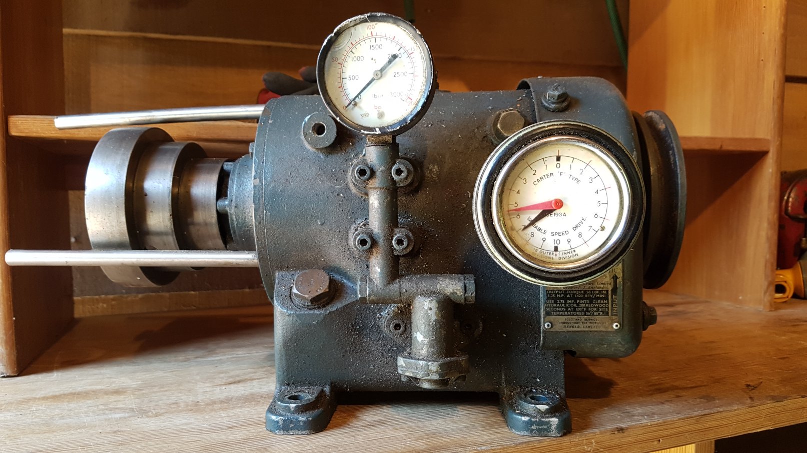
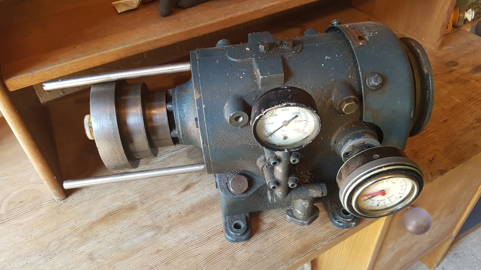
If I thought a radius-turning attachment was interesting, I've now got to possibly the strangest thing to come with this lathe : a variable speed hydrostatic transmission.
vsd-front.jpg

Apparently the previous owner ran an engineering company and so presumably decided to be inventive with the drive system for the lathe. This does not look like the sort of component you would pick up at a hobby store. There's an input pulley one end, and an output the other, and filler-drain plugs for hydraulic oil, together with a pressure gauge that hints at some pretty interesting pressures in there.
vsd-overall.jpg

Hence we have this enormous single-phase motor, and this variable speed transmission. I haven't fired it up yet, but I suspect it's using the input drive to run a hydraulic pump, the output from which operates a kind of swash plate motor where you can vary the pressure or angle in some way to vary the output speed. So probably pretty torquey. The dial with the two hands is actually a knob that you can rotate through eight or ten complete revolutions, causing the red needle to move around the dial and the black needle to follow at 1/10 speed. It's a symmetric dial which matches the idea that the drive is, I think, reversible.
vsd-label.jpg

So while my initial thought was to get a new 3-phase motor and VFD to run the lathe, I'm kind of intrigued to get this going and see how it does. It's going to need one heck of a mounting bracket because the motor/vshd combo weighs a staggering amount, but worth a go.

So, apart from entertainment value, does anyone have experience of these drives in terms of relability, effectiveness, noisiness etc ? The motor I have almost got cleaned up and back together, so I'll hopefully be able to try things soon.

Richard
 

Attachments

  • vsd-front.jpg
    vsd-front.jpg
    275.1 KB
  • vsd-overall.jpg
    vsd-overall.jpg
    294 KB
  • vsd-label.jpg
    vsd-label.jpg
    313.3 KB
Can't hurt to run it up and see what it's like. I would imagine it will be pretty quiet, and 100% it'll give more torque than a VFD.
 
Back
Top