Hi Mark,
It was windy today in Northants, I struggled to open my car door just as R4 was warning of 50mph winds. If it was like that in Devon, not a day for clambering over your roof with an 8’ x 4’ sheet of plywood.
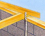
Ceiling joists: If you accept more deflection, make your ceiling as light as possible and of material that won’t show cracks you can minimise the section of the timber tie. A T&G matchboard ceiling looks good in a “cabin” is comparatively light and any movement is accommodated by the numerous joints between the planks. On the other hand, due to all the joints it does not provide the racking resistance that a sheet ceiling would. So maybe plywood panels with cover strips at the joints would be better if acceptable to you aesthetically.
Bosshogg suggested a smaller tie than shown in the tables. Timber is quite good in tension as long as the area available for fixing is adequate. What I mean is that sometimes the local stresses around the nails or bolts at each end dictate the size of the member. In your building 220 x 50 is more than you need.
I think I posted the book extract comparing roof structures after you had decided to go with rafters. Had you seen that earlier and chosen an all purlin roof, as the BR Part A table for purlins supporting sheeting, you could have made a stressed skin panel for each roof slope, ply sheathed both sides, strong, light and simple.
I think you must now decide what you want and stick to one track. It will be simpler for you to follow bosshogg’s directions to complete your roof and you will have the benefit of his experience to guide and reassure you.
If you really have to have an open roof free of ties and hangers etc it will cost you in time plus the additional materials. In outline, one way to do this would be as follows:
I note what you say about providing support for the purlin ends at the gables. With this in mind I suggest that if you really want to pursue this idea you adopt two purlins per slope located so they are as near as possible equally spaced whilst falling above a section of solid wall, that is, not above a door or window opening.
Place the purlins vertically and use short studs within the gable panels to prop and contain the purlin ends. It’s like forming a box around the end of the purlin so it is held in place and can’t wind (twist). If you cut away the ply face the purlins can pass through and project to form the principal supports for your verge ladders. To set out the purlin positions you would first mark the line of the underside of your rafters on the gable ends. Then set the outer top corner of each purlin so that it does not cut into the rafter beyond 1/3rd of the rafter’s depth whilst providing not less than 50mm horizontal bearing for the birdsmouth.
Below the new purlin locations you would need to ensure enough support to spread the loads into the wall frame and down into the floor perimeter beams and thus to the foundations. That’s not as hard as I have made it sound, just add studs below the load so there is a vertical load path to the floor perimeter beam.
I would replace your ridge board with a proper purlin. However, because you have already cut your rafters to lie against the existing ridge board I would lift the ridge purlin and plant (glue and screw) timber ledgers to provide a bearing for birdsmouths at the top of the rafters. Now you can re-use your existing rafters by cutting them to fit.
Don’t forget that as your purlins are long (relatively in structural terms) they need to be restrained to prevent winding (twisting). You could put solid blocking between the purlins after you have fixed your ceiling. I assume that you will part fill the rafter depth with insulation and pin a ply, or whatever, ceiling to the underside of the rafters between the purlins.
Re your comment that you had little down on paper: I find it really does help to sketch out what you want to do. The process of drawing makes you think about how parts come together and generally shows up potential problems. Quick freehand sketches are all you need to work out the basics. CAD, Sketchup etc are good for the later stages when you need to put dimensions on parts but you can be trapped in the process of drawing which kills spontaneity. A quick sketch has little penalty of time attached so you can screw it up and do another without feeling bad.
I hope this answers your question and give you more to think about.
I am sorry to say that I cannot spend any more time on this as I have work to progress and need to devote all my time to it whilst the weather is ok.
Graham
 I think communication lines are getting crossed at times, could we figure out how to resolve this?...bosshogg


