Finally I turned my attentions to the adjuster...
I had used the head of a 265 mm M10 bolt to make the cap iron screw - so I used the rest of the bolt for the adjuster screw. First I turned it down on the lathe and then cut a 5/16" 40 TPI thread in one end (I was using a Norris adjuster here to guide me on the proportions etc
I drilled and tapped an offset of a 3/4" mild steel rod to make the corresponding anchor for the adjuster
.
Then, with apologies cos my phone was not charged on sunday am, so I have missed out a few steps, I cut a similar length offset of 3/4" steel pipe for the retainer, and then used the lever cap screw from my St James Bay infill kit which I had not used originally to provide a brass head for the adjuster
The retainer (i.e. the thing which holds the cap iron screw captive) I drilled 2x 4mm holes through the walls opposite each other on the mill
I drilled a 3.5 hole into the screwed end of the adjuster shaft on the lathe then tapped this by hand with a M4 tap
The inside of the retainer piece I enlarged with a series of diamond and HSS burrs using a Dremel to countersink it - I do not have a countersink small enough to get in there
Then it was just a question of patience and an M4 countersunk bolt to get it all to fit together
I used a small washer between the retainer and the shaft which meant I could tighten up the screw until the retainer would rotate but there was no play. I can take a more detailed photo of this sometime to demonstrate
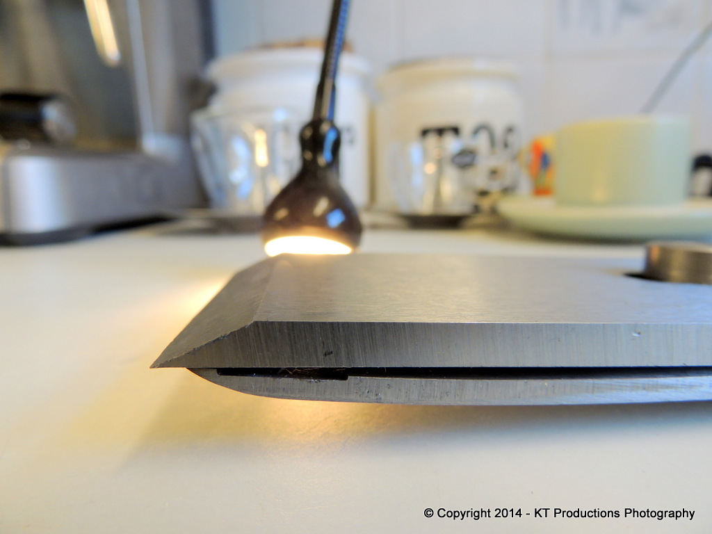
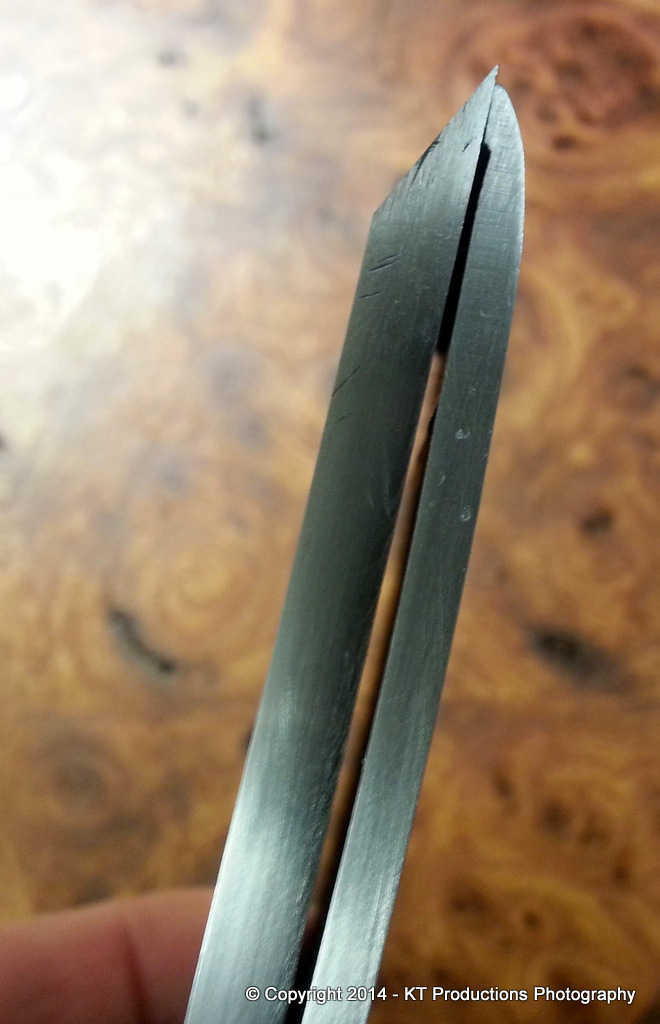
So by the end of yesterday I had got to this stage with the whole blade / cap iron / adjuster mechanism arranged on the bench to show how it would work. I am using Richard's brilliant alternate suggestion as to how to mount the adjuster using a 1/4" steel rod in a short brass tube sunk in the infill
Sorry if some of that is not clear but as I say the lack of a camera meant I missed some crucial shots
Cheers Mark


