Boley No. 3L screw cutting lathe restoration

UKworkshop.co.uk

Help Support UKworkshop.co.uk:

This site may earn a commission from merchant affiliate links, including eBay, Amazon, and others.

MusicMan

Established Member
UKW Supporter
Joined
1 Jul 2015
Messages
2,036
Reaction score
163
Location
Warwick
This thread (which will take a while to complete) is about the restoration of a Boley lathe that I bought from marcros of this forum. We'd originally communicated about it when he bought the lathe, but when his plans changed and he needed the space he kindly offered to sell it to me for spares for my own Boley No. 4, which we thought it was. On seeing it though, it turned out to be a rather complete Boley No 3L (90 mm centre height not 120 mm), screwcutting, with a complete set of change gears. I think it probably dates from about 1920 - 1925; a slightly earlier version than one shown as 1925 on lathes.co.uk.

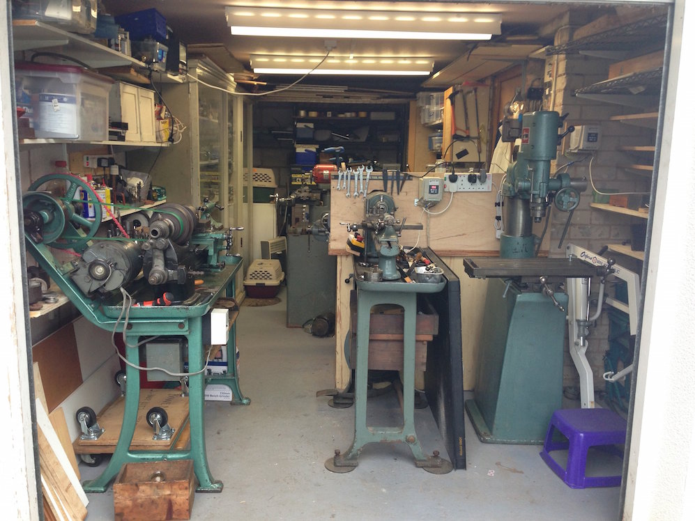
This is my metal workshop at present.
workshop.jpg


The Boley 4 is at the front left. As you see, it is a screwcutting lathe with good size capacity, though I do not have all the change gears by any means. To the right of it is a Boley No. 3C plain turning lathe. This is a very nice machine from the 1930s, but the lack of screw cutting or power drive is an issue for me. Amazingly, the spindle runout is only about 5 microns after 100 years use! btw that's an Arboga mill on the right.

The new change gears that came with the Boley 3L unfortunately don't fit the 4L. So after humming and hahing to myself I've decided to replace the 3C with the 3L when it is rebuilt. I found a space for it on a strong cupboard/bench that I made about 40 years ago to hold 12" LPs.
So here is the starting point with the lathe mounted on the base with screws from beneath (the socket at the right hand end was broken, but that's no big deal).

Boley 3L - 1.jpg


Here are the precious gears:

Boley 3L - 2.jpg


and here's the back with the motor layshaft assembly not yet mounted.

Boley 3L - 3.jpg


So the present stage is that the lathe is mounted, the holes for the layshaft assembly done so that the belt drive can be aligned with the pulleys, and the cross- and long- slides have been nicely adjusted so that they run smoothly without play. I've examined the main slides with precision level and precision straight edge and the slide wear is very low. I can't get a 0.02mm feeler under the straight edge anywhere, and the carriage runs smoothly all the way without undue looseness or sticking. So it should be a decent screw cutter.

I then came to mount the layshaft assembly and hit the first disaster. The base, which carries the trunnions to allow the layshaft to be loosened and tightened and belts easily changed, broke :-(. I didn't drop or shock it at all, but there was a heavy self-weight on it as I was manipulating it into place. The break matters as it aligns the motor/layshaft plate.

Boley 3L - 4.jpg


On examining the break with my metallurgist's eye, I could see a quite big discoloured area, where the crack had obviously been growing for a long time, probably years.

Boley 3L - 6.jpg


So not surprising that it would go, and better now than when I have it all rebuilt and working.

Hmmm, what're the options? Cast iron is notoriously difficult to weld or braze, and the joint is going to be under vibratory stress so needs to be strong. I could epoxy and dowel pin/screw it, though there is a risk of another crack happening as I do that. I could machine another base plate with trunnions fairly easily, but I'd like to explore getting it repaired by a specialist cast-iron repairer. So on Monday or Tuesday I'll be taking it to https://www.shiltoncastironandwelding.co.uk/contact/ at Hinckley (not far from me) with a view to them repairing it. It's probably going to cost a bit but it would be good to keep the lathe as original as possible. They'll do a crack inspection of the component first, and see if there are any other cracks lurking unseen, but if there is just the one main break I think I'll go ahead with that. It will take about three weeks, so back to the rest of the machine. Watch this space if you are interested!
 

Attachments

  • workshop.jpg
    workshop.jpg
    166.1 KB
  • Boley 3L - 1.jpg
    Boley 3L - 1.jpg
    168.8 KB
  • Boley 3L - 3.jpg
    Boley 3L - 3.jpg
    227.1 KB
  • Boley 3L - 2.jpg
    Boley 3L - 2.jpg
    200.4 KB
  • Boley 3L - 4.jpg
    Boley 3L - 4.jpg
    221.8 KB
  • Boley 3L - 6.jpg
    Boley 3L - 6.jpg
    69.4 KB
Shame about the break. Would the pro repair be cold stitching? It’s an incredible process - an art form really.

I hope it doesn’t break the banks.
 
Any millage in providing a thin sheet steel plate under it with a couple of steel dowels into the 'broken' piece to reinforce and spread the loads across the repair once it has been completed.
Plate.jpg


Or bond with a good epoxy instead of the steel dowel pins.
 

Attachments

  • Plate.jpg
    Plate.jpg
    2 KB
For what its worth i have seen similar breaks welded up, its a matter of veeing out each side & preheating the cast iron parts. Rods are a nickel alloy if i remember correctly. Alternatively as its basically just a flat plate with bosses you could cut a plate from steel plate & weld two bushes to it with flats machined on their undersides.
If its any consolation my Boley has two castings that may need replacement, these are the two blocks that hold the leadscrew nut to the saddle, both have been broken & welded up but not very well, I think it likely i may have to machine two new ones.
 
Keith 66":3aenozwo said:
For what its worth i have seen similar breaks welded up, its a matter of veeing out each side & preheating the cast iron parts. Rods are a nickel alloy if i remember correctly. Alternatively as its basically just a flat plate with bosses you could cut a plate from steel plate & weld two bushes to it with flats machined on their undersides.
If its any consolation my Boley has two castings that may need replacement, these are the two blocks that hold the leadscrew nut to the saddle, both have been broken & welded up but not very well, I think it likely i may have to machine two new ones.

Thanks Keith. It's out to a specialist cast iron welder atm and yes he uses the preheat method. Waiting for him to come back after crack testing to ensure it is worth it.

The underside is not flat all over as it has three machined flats that are slightly proud (to define the flat plane for mating with whatever it goes onto). Yes, my fallback is fabricating one, as you suggest.

Keith
 
Nice post Music Man (and VERY nice machine too - beats my Chinese Mini Lathe hands down)!

Please keep up the good work and I's be VERY interested to know what that cast iron repair costs (assuming the crack detection show it's worth repair). BTW, just for my own general interest, I'd like to know what crack detection process/es they use - dye penetrant, eddy current, etc, etc?

Thanks
 
Thanks AES. It did come out well, just got it back. It cost £144 inc. VAT and leaving me to machine off some of the filler. The crack detection was MPI (magnetic particle inspection). Eddy current is little use on grey cast iron as it is full of carbon flakes which look like cracks! Photos soon!
 
OK, thanks for that MM. I don't have much more than theoretical experience of NDT on cast iron (not too much of it to be found on aeroplanes!!!) hence my Q.

That really is a nice machine. How are you going to "smooth off" the weld fillet? Flap disc in an angle grinder?
 
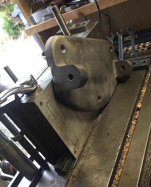
OK taking up the story after a long break for various reasons I shan't bore you with. As said, the weld came out very well but with an awkward bit of fettling to do. The problem was holding it and registering it with the flats underneath the part. Inspiration struck and I turned my magnetic clamp on its side, finding happily that the whole was still square to the miller table. The plate could then register on the flats, at the back in this picture.
Boley3L - 2.jpg


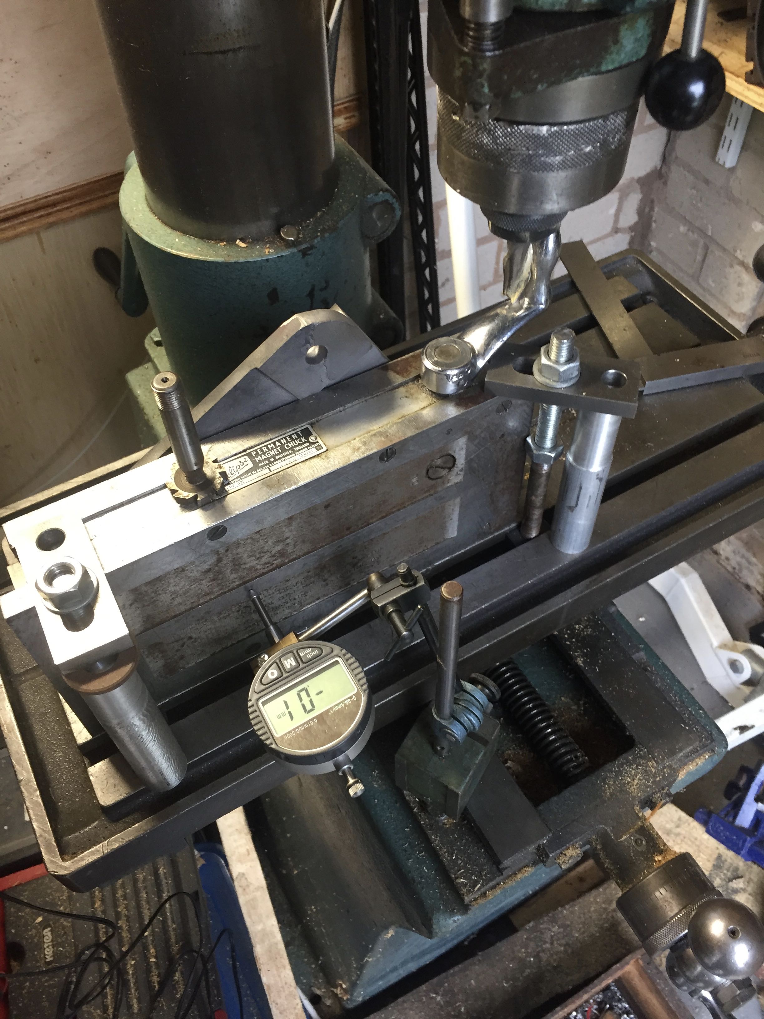
and from the front, with extra clamps to keep it all solid. The bit projecting at the top is way needs to be machined.

Boley3L - 1.jpg


All carefully indicated in so that the magnetic table was parallel to the traverse.

Switch the miller on and nothing happened. The 3-phase converter had failed after 6 or 7 years happy running.

Pause to determine that it is incurable, don't want to launch out £400 for a new one, so borrowed the converter from the Boley 3C lathe.

More soon.

Keith
 

Attachments

  • Boley3L - 2.jpg
    Boley3L - 2.jpg
    60.4 KB
  • Boley3L - 1.jpg
    Boley3L - 1.jpg
    738.2 KB
Now for trimming the surplus, using the side of an end mill.
Boley3L - 6.jpg


It cut ok but the tool was a little short. Pause while a long type was bought from Cromwell Tools, with their usual overnight delivery - excellent company. Now it worked. The shorter tool had unfortunately 'bumped' in a couple of places - cutting on the side of en end mill is not ideal - but it got the job done, and the flat was nicely co-planar to the other flats (checked on a surface plate).
Boley3L - 12.jpg


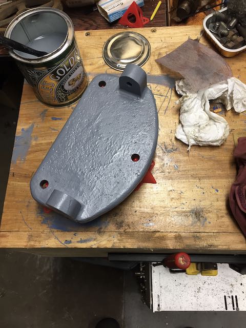
and now undercoated. I'm using Tractol machinery enamel from Smith and Allen, following a recommendation from deems (thanks, it's good!). Dark Grey undercoat, which will be followed by Pigeon Blue topcoat.

Keith

Boley3L - 13.jpg
 

Attachments

  • Boley3L - 6.jpg
    Boley3L - 6.jpg
    99.2 KB
  • Boley3L - 12.jpg
    Boley3L - 12.jpg
    108 KB
  • Boley3L - 13.jpg
    Boley3L - 13.jpg
    68.2 KB
Isn't it nice, how one job (repairing the new lathe) justifies having the big old mill and magnetic chuck, ready and waiting? :)
 
That's exactly why you can never have too many tools! I got the magnetic chuck for a very different project, which in the end got abandoned for good reasons. It has sat there unused for a few years. Took me a while to figure out how to hold this piece - the three flats on the bottom were the only flat parts, and it was awkward to register it against the face that needed machining - then I remembered this chuck and was happy to find that the side was accurately perpendicular to the magnetic face.
 
So now for the painting orgy. I didn't want to dismantle the headstock/spindle, nor the unique Boley carriage. This surrounds the bed, allowing the lead screw to be central, exactly beneath the main spindle axis rather than off to one side. This gives great precision but is a bit fiddly to dismantle, and it wasn't broke so I didn't fix it. Not too hard to paint it in situ though. First the undercoat:
Boley3L - 9.jpg


Boley3L - 10.jpg


Boley3L - 11.jpg


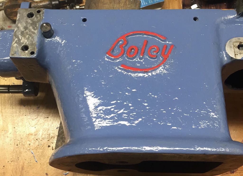
then the topcoat plus the Boley name highlight:
Boley3L - 16.jpg


Boley3L - 17.jpg


Boley3L - 8.jpg


Keith
 

Attachments

  • Boley3L - 9.jpg
    Boley3L - 9.jpg
    42.9 KB
  • Boley3L - 10.jpg
    Boley3L - 10.jpg
    75.9 KB
  • Boley3L - 11.jpg
    Boley3L - 11.jpg
    95.3 KB
  • Boley3L - 16.jpg
    Boley3L - 16.jpg
    95.7 KB
  • Boley3L - 17.jpg
    Boley3L - 17.jpg
    102.2 KB
  • Boley3L - 8.jpg
    Boley3L - 8.jpg
    86 KB
Now turning to the top and cross slides, which need to work smoothly without wobble or yaw. That was simply achieved by cleaning and oiling with heavy way oil, and adjusting the gib plates. There wasn't much wear on the lead screws/nuts and anyway backlash is unimportant here. Almost all lathes have some, and one gets into the habit of cutting in one direction only.

The trickiest part was in adjusting the hand wheel mechanism so that the backlash was minimised, the wheels turning freely, and the dial indicator able to turn independently of the wheel. This is all quite fine tolerance stuff on this old a machine. My later Boley have a double nut mechanism to adjust the position and tensions more readily. This one just has to have the length and diameter tolerances right on each component. This was managed with a bit of reaming and emery lapping.

Fastening the handles on took a while to puzzle out. The topside screw was missing and was easily replaced with an M3 cap screw, though I shall get or make one with a wider c/s cap to replace this.

Boley3L - 20.jpg


One pleasure about using old continental machines is that they are metric throughout. Unless they have been serviced or fixed up in England! The cross-slide retaining screw baffled me:

Boley3L - 19.jpg


I attacked it with micrometers, verniers, a travelling microscope and thread gauges (really hard to see at this pitch for old eyes even with magnifiers!) , till I satisfied myself that though it was about 3.5 mm diameter, it was no metric size whatsoever. Turning to Imperial, it turned out to be a good match for 6-40 UNF ! Other signs of tampering on this drive confirmed that it had been repaired by someone without access to or interest in metric threads!

I could put a 3 mm Helicoil insert in, but the UNF screw fits well enough and works, so it ain't broke. I'll leave it. So, after cleaning up the knobs and handles the carriage is ready.

Boley3L - 21.jpg


I also painted the motor drive base plate (the thing that was welded) and the pivoting motor carrier. When the paint is dry I'll get on with mounting the drive mechanism and attaching/aligning a new belt. Then it's just the gears to clean up.

Keith
 

Attachments

  • Boley3L - 20.jpg
    Boley3L - 20.jpg
    740 KB
  • Boley3L - 19.jpg
    Boley3L - 19.jpg
    107.2 KB
  • Boley3L - 21.jpg
    Boley3L - 21.jpg
    153.5 KB
Here is the motor mount painted, and a few gears put in to judge the overall dimensions for the gear shielding:

Boley3L - 1 (1).jpg


Now the layshaft cleaned up, and decent flats put in to take the set screws. The miller comes in handy again.

Boley3L - 3 (1).jpg


Lining up the pulleys (left/right and in twist):

Boley3L - 4 (1).jpg


Now the belt is cut to length, fastened with alligator clip and mounted.

Boley3L - 1 (2).jpg


I'm not actually happy with the belt. I see that I ordered it too wide. There should be a couple of mm either side to stop it riding up on the pulley flange for the top speed. Have ordered a narrower one, but this was good practice. Plus a bloodied thumb on hammering in the alligator!
 

Attachments

  • Boley3L - 1 (1).jpg
    Boley3L - 1 (1).jpg
    120.5 KB
  • Boley3L - 4 (1).jpg
    Boley3L - 4 (1).jpg
    132.9 KB
  • Boley3L - 1 (2).jpg
    Boley3L - 1 (2).jpg
    170.5 KB
  • Boley3L - 3 (1).jpg
    Boley3L - 3 (1).jpg
    124.7 KB
I found working on my pantograph a pleasure - only need to grab the metric kit. Much easier than the last saw I did which was a mix of UNF/UNC and whitworth. Let me know if you need a hand with making the gear shields, something I can probably run up at work. (don't think you're a million miles from me)
 
That's a very kind offer, and no, not far and I visit relations in Leicester from time to time. I was going to make the shields out of plywood and heat-bent polycarbonate. What sort of stuff/materials/shapes can you do at work?
 
Most of our stuff is thin sheet metal (up to 1mm mainly but can handle up to 3mm easily) stainless or aluminium. Got a box/pan folder, rollers and a pittsburgh lock former so most flat shapes are achievable.
 

Latest posts

Back
Top