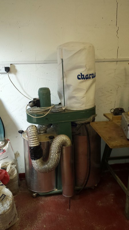
thien or cyclone

UKworkshop.co.uk

Help Support UKworkshop.co.uk:

This site may earn a commission from merchant affiliate links, including eBay, Amazon, and others.
Matt, I will be close. We will be at a relatives house in cuckfield monday evening before flying out of Gatwick on Tuesday.
But I would have a problem getting it on the plane as our baggage allowance is only 20 kgs each and our cases are full as I've already been to axminster basingstoke (lol).
 
MattRoberts":3hnpog57 said:
Ah, OK no worries. I could always post some to you at cost if you can't get some out there for a decent price. Safe journey
Matt, is it 3mm plexiglass? I've got some for a build but haven't tried bending it yet. A 34cm circle is smaller than I've seen before so did you have problems making the cylinder?
 
It's 2mm (or maybe even 1.something mm) plastic sheet. No problem making the cylinder - you'll see in the photo I have a second circle of ply inside the cylinder at the top and bottom. It was just a case of wrapping the plastic round it and screwing it with drywall washers. The dowels hold the top and bottom discs in place, and therefore the plastic doesn't deform
 
MattRoberts":1s09y39s said:
It's 2mm (or maybe even 1.something mm) plastic sheet. No problem making the cylinder - you'll see in the photo I have a second circle of ply inside the cylinder at the top and bottom. It was just a case of wrapping the plastic round it and screwing it with drywall washers. The dowels hold the top and bottom discs in place, and therefore the plastic doesn't deform
Thanks
I have 3mm but would attempt something around 50cm diameter, so we'll see if I'm lucky or not!
 
Hopefully it will be fine over that diameter. I can always post some of this stuff to you as well if you need.

To be honest, I bought extra because I expected my first thien design to fail! Who would have thought I'd ace it :D
 
when you want to bend the plastic just use a hair dryer to warm it. keep the hot air moving and get it to just too hot to hold and it will bend easily. the plastic will discolour just before it melts, but its very easy to make tight curves in it.
 
Is your extractor the SIP 01929 - the 1.5hp HPLV one? A cyclone for that should be about 6" diameter and an inlet size of around 2.5". When you say your cyclone is 3" - do you mean that is the diameter of the inlet or the diameter of the cone at the top?
 
I made this for my kity extractor:
Extractor
Works very well. Its a thein plate in the top of the left can, theres a viewing window in the can to see how full the bucket is (obscured by the hose) Very easy to make and its nice and compact.
 
sunnybob":30ji31sf said:
when you want to bend the plastic just use a hair dryer to warm it. keep the hot air moving and get it to just too hot to hold and it will bend easily. the plastic will discolour just before it melts, but its very easy to make tight curves in it.
Yea, I had to do that when I made the curved sections on this http://spikyfish.com/DustExtraction/

The problem is that I used acrylic, because at the time (more than 10 years ago) I didn't know it was the wrong stuff!
 
siggy_7":17x6bdiy said:
Is your extractor the SIP 01929 - the 1.5hp HPLV one? A cyclone for that should be about 6" diameter and an inlet size of around 2.5". When you say your cyclone is 3" - do you mean that is the diameter of the inlet or the diameter of the cone at the top?

yes, the 01929. 100 mm inlet. The cyclone is made from a midi sized traffic cone about 30 cm across the top and around 40 cm high. I've fitted 62 mm tube to both inlet and outlet, and the rest of the ducting is also 62 mm.
I would guess it to be around 95% efficient in terms of collecting stuff, but its too much of a restriction in the line as I am slowly upgrading the whole system to larger pipes so as to extract more from the actual machines.
I'm planning either a larger cone with 100 mm tubes, or a larger thien over the top of the cone.
 
Ok. I think your extractor is rated to about 50 litres/sec of air (according to Toolstation's website anyway). In 62mm diameter pipe, the mean flow speed works out to be about 16.5m/s, which is about the minimum you want to avoid material falling out of suspension in the air stream (most people use 20m/s as a good design minimum). Your pressure loss in the pipework works out to be about 50Pa/m or roughly 5mm water per m, which is basically naff all restriction. Can I ask what makes you think that your system has a significant flow restriction? Whatever it is, I don't think it's your ducting - it would appear to be nicely sized for the extractor you have and I don't think you will see any benefit with going bigger.

Your cyclone design I presume just has the cone and not a cylindrical section at the inlet? The maximum cone diameter would seem to be quite generously sized for the air flow you have, so I don't think that would be providing much of a restriction either. I'll have a look over my cyclone design notes later (I don't have them at work) and check it properly for sizing.
 
I made a cyclone out of a traffic cone, it was going to be a mark 1 and planned to using it as a starting point. But worked so well it has been in used for almost 2 years. Only thing that gets through is a little very fine powder like dust. 63 mm inflow (drain pipe), into upside down traffic core from the side, bit of clear plastic over the top of the cone (wanted to be able to see if it worked) into large plastic blue drum. Outflow is about 55mm flexible pipe to a record power shop van.

Looks a bit ruff as it was going to be a development but does the jod and cost nothing as it was what I had or could scrounge.
 
I've had a look through my notes now. I reckon your cyclone pressure drop should be around 180mm of water, which is close to ideal for maximum separation efficiency of fine dust. However, as previously stated, I think your fluid velocities in the top of the cone are likely to be really low because your cone and ducting sizes are so large compared with the flow rate. Your cyclone also doesn't have a cylindrical section on top of the cone which will reduce the efficiency a bit. Your use of a (presumably) round inlet is also not ideal. Pentz and others recommend a 150mm diameter cyclone used with 62mm ducting for vacuum type extractors (the ideal cyclone diameter is about 3 times the outlet diameter) - if I were in your position I would look at building a smaller cyclone with a rectangular inlet. His design notes for a 6" cyclone should be instructive.

What I expect is happening at the moment is that the incoming fluid velocities are sufficiently low that instead of being forced down the cyclone, a sufficient flow volume is able to travel from the inlet across the cyclone lid to the outlet which is taking entrained larger particles with it. What your cyclone needs to be doing is to force more of the air down into the cone - hence my recommendations to look at the inlet design and reduce the size to get flow speeds up.
 
Sorry for delay, I am now back home.
Actual measurements of the cyclone are ;
height 35 cm. diameter at wide end 16 cm, diameter at narrow end 8 cm.

The top is flat ply with a central hole and the 62 mm plastic pipe is set at half the height of the side entry circular 62 mm hole. This pipe is immediately connected to the 100 mm pipe from the sip with only 30 cm of 100 mm pipe to the main drum.
The rest of the system is all 62 mm pipe with blast gates at each machine. Total run of pipe is around 5 metres.

I first had it set with the top tube down below the bottom of the side entry, but realised that meant it was so close to the cone sides that stuff was being sucked through into the main drum.
With it set at half the height only very large clumps of shavings get sucked through, but the air filter in the main drum gets badly clogged with fine dust.
i am hoping to greatly reduce the fine dust aspect by making a larger cone (or thien baffle).
 
Ok. Based on your dimensions, I think your pressure drop is around 200mm of water and your 50% particle separation efficiency should be about 1.3 microns. This compares quite well with other designs - for example, Bill Pentz's 18" cyclone with 1,000 CFM air flow works out to give a pressure drop of 160mm water and a 50% separation efficiency of around 3.5 microns. I am using some theory published here to get to these numbers, if you are interested: www.svarovsky.org/fps2/GASCYC.pdf

What is the configuration that you have attached below the cyclone? The separation efficiency is negatively affected if it is not sealed as you can then draw gas in from the bottom of the cyclone cone. Also, you need a clear space below the bottom of the cone (i.e. don't let debris build up near to the bottom of the cone in the hopper).

Your cone dimensions are quite different to Pentz's - the slope of the cone is a little over half that which he recommends (as a result your cone length ratio is higher) and the hole at the bottom of your cyclone cone is quite a bit bigger than the inlet and outlet ducts. The vortex cone in the cyclone reaches a long way down - because of your large dust discharge hole diameter, I suspect it may be going right down into the hopper itself.

Lastly, the inlet design on a cyclone is really quite critical. The objective is to get the inlet material swirling down round the inside walls of the cyclone as smoothly as possible. For this reason, inlets generally are rectangular in section to bias the inlet flow towards the wall of the cyclone cone, are often introduced at a downward angle to give the incoming air downward momentum into the cyclone cone, and sometimes use a ramp to also give the air more downward momentum and minimise mixing with the inner vortex which is flowing upwards towards the cyclone air outlet.

Based on the described performance of your system, I am quite convinced that you should be expecting better separation performance than you are getting. However, I really do think that the cyclone you have built is overall sized very well for your system - it's some design detail that is not right. I don't think just building a bigger cyclone or Thien baffle is the right answer - although if you happen to get the design of that right, then you may find the performance is better. Cyclones are tricky things to get right, but worth persevering with. I hope some of this is helpful to you - and happy to be of further assistance if required.
 
siggy_7":lff9pfes said:
Ok. Based on your dimensions, I think your pressure drop is around 200mm of water and your 50% particle separation efficiency should be about 1.3 microns. This compares quite well with other designs - for example, Bill Pentz's 18" cyclone with 1,000 CFM air flow works out to give a pressure drop of 160mm water and a 50% separation efficiency of around 3.5 microns. I am using some theory published here to get to these numbers, if you are interested: http://www.svarovsky.org/fps2/GASCYC.pdf
Do you know if that document is relevant for Thien designs?

There's a lot of information about on good designs for cyclones but I feel a little bit in the dark with a Thien design. It would be great to have some data behind the design before I actually started building something. I.e. given a blower with a certain HP & CFM what Thien diameter and height would be good, slot width, protrusion of outlet pipe into the enclosure etc.
 
Siggy, I shall take pictures tomorrow, and am definitely interested in continuing the maths lesson (my brain doesnt cope well with this stuff anymore).

The cone exits into a large rectangular plastic box. This is an area I had definitely planned to upgrade as its an Ikea storage box, with the lid clipped down with a lot of ikea clips. The seal isnt 100%. Its good, but not perfect.
I never let the box get filled, usually emptying it when the dust level is still 100 mm from the bottom of the cone.
The side inlet is horizontal, but it would be fairly easy to tilt that downwards.

From my observations, the amount of tube sticking down vertically has a significant effect on performance, too low and the stuff is sucked from the side wall, too high and it goes straight from inlet to outlet.

I did experiment with a full sized motorway cone, but it collapsed when used and I could not be bothered to make a cradle for it.
 
The document I linked to is explicitly for cyclones and I doubt that it is directly relevant for Thien designs. However, if I were designing a Thien baffle, then I think to a first approximation I would:
  • Size the inlet and outlet diameters to be about the same and of comparable size to my ducting, ideally sized so that the flow speed is ~25m/s for my expected flow rate;
  • Calculate the Euler number from a proposed diameter of the separator, inlet and outlet;
  • Estimate the pressure drop from the Euler number;
  • Fiddle about with the design parameters (in particular the separator diameter; I would leave inlet and outlet sizes fixed once worked out in step 1) until I got to a pressure drop I was happy with. An educated guess would be to have a pressure drop of about 100mm water to get reasonable separation without being too restrictive.

I think the other design parameters of a Thien baffle are relatively fixed - see here: https://woodgears.ca/reader/hector/thien_separator.pdf
 
siggy_7":1pasojwy said:
The document I linked to is explicitly for cyclones and I doubt that it is directly relevant for Thien designs. However, if I were designing a Thien baffle, then I think to a first approximation I would:
  • Size the inlet and outlet diameters to be about the same and of comparable size to my ducting, ideally sized so that the flow speed is ~25m/s for my expected flow rate;
  • Calculate the Euler number from a proposed diameter of the separator, inlet and outlet;
  • Estimate the pressure drop from the Euler number;
  • Fiddle about with the design parameters (in particular the separator diameter; I would leave inlet and outlet sizes fixed once worked out in step 1) until I got to a pressure drop I was happy with. An educated guess would be to have a pressure drop of about 100mm water to get reasonable separation without being too restrictive.

I think the other design parameters of a Thien baffle are relatively fixed - see here: https://woodgears.ca/reader/hector/thien_separator.pdf
Thanks.

I use the motor and blower unit from a Fox F50 843; claimed 3hp and around 3900m^3 / hour. For various reasons I'm probably going to look at making a portable machine with no ducting in the workshop, and it lends itself well to having a couple of 4" hoses (i.e. around 6" effective inlet and outlet).

If my dodgy maths skills are right, a 6" round inlet, with air being pulled at 3095m^3 / hour, should result in an airspeed of around 59m/s; ignoring losses.

Does the document you posted explain how to calculate the Euler and pressure drop values (I'm on a phone at the moment so it's not the easiest to check)?
 

Latest posts

Back
Top