


The normal profile for Raised Panels (RP) is that the part that sits in the stile/rail is a parallel section ( hence this profile on router cutters) to allow for movement. I have seen a number of examples particularly those that are cut on a table saw and by hand plane where there is no parallel section just the tapered edge, how can this work?. If the panel expands it will just lock up against the taper, if it contracts it will just fall out unless it was a very loose fit to allow more of the taper to enter stile /rail, but it would then rattle.
You are using an out of date browser. It may not display this or other websites correctly.
You should upgrade or use an alternative browser.
You should upgrade or use an alternative browser.
Raised panel question
- Thread starter newt
- Start date
Help Support UKworkshop.co.uk:
This site may earn a commission from merchant affiliate
links, including eBay, Amazon, and others.
Perhaps it's "gripped" at top and bottom by the frame which prevents it from rattling but allows for expansion accross it's width - in turn allowing for some of the taper to enter the side frame. At least I hope that works or I'll have an exploding frame soon ")
Cheers Mike
Cheers Mike
Philly
Established Member
Pete
It would seem rattling panels was a standard thing in the days of common panelling. The same profile would of been made with the common badger plane (which was used a lot for raising panels). Obviously, if you used a panel raising plane (like I have recently made) you can make a raised panel with a parallel tongue which allows for a snug, rattle-free fit. But these planes are rare (expensive??) so rattling panelling was the norm (from what I can gather!)
Hope this helps
Philly
Paul Chapman
Established Member
Pete, this has always puzzled me as well, because most of the books I've read show drawings of the fielded door panels with a tapered edge. However, I have looked in my recently acquired "Techniques of Furniture Making" by Ernest Joyce and Alan Peters and the illustration in that shows the parallel section where the panel enters the groove, which I think is the correct way to do it. I think it comes down to what planes you have available. You should be able to do it with the parallel edge if you get that large shoulder plane you were on about
Cheers :wink:
Paul
Cheers :wink:
Paul
I believe the parallel panel edge came in with the use of the spindle moulder as before it appeared (in the period 1860 to 1880) almost all panels would have been fielded using a badger plane or the like. With a spindle moulder it is quicker and easier to set a consistent depth of cut, especially batch to batch, if the panel edge has a small flat land.
Although I could be wrong, here....... :? Would any of our restorers care to comment?
Scrit
Although I could be wrong, here....... :? Would any of our restorers care to comment?
Scrit
A
Anonymous
Guest
Tapered panel wouldn't necessarily rattle as in reality it'd tend never to be that loose, due mostly to slight warping which would hold it sprung in the slots. In the longer term it'd pick up dust, varnish etc which would fix it a bit more
It wouldn't take much to stop it rattling and still be loose enough to move relative to frame, with humidity variations.
cheers
Jacob
It wouldn't take much to stop it rattling and still be loose enough to move relative to frame, with humidity variations.
cheers
Jacob


£26.99 (£1.35 / count)
VEVOX® FFP2 Dust Mask - Set of 20 - Valved Face Masks - Respirator - Protection e.g. for Construction, Building Work, Sanding, Woodworking, Fine Dusts, Aersoles or Particles
SLSK Ventures GmbH (UK)


£19.46 (£3.89 / count)
£19.99 (£4.00 / count)
Stealth Lite Pro FFP3 Face Masks UK Certified Dust Mask. 99.99% particle filtration, air filter reusable face mask. FFP3 Mask -7 day use per Construction, Woodworking, DIY and Welding Mask
Amazon.co.uk


£17.99 (£1.80 / count)
£27.44 (£2.74 / count)
3M 8822 Disposable-fine dust mask FFP2 (10-pack)
Amazon.co.uk


£12.50 (£1.25 / count)
£14.45 (£1.44 / count)
JSP M632 FFP3moulded Disposable Dustmask (Box of 10) One Size suitable for Construction, DIY, Industrial, Sanding, dust protection 99 Percent particle filtration Conforms and Complies to EN 149
Amazon.co.uk


DomValente
Established Member
The panelling at Hampton Court palace is fielded at least in the Wolsey library where some years ago there was a fire, new panels had to be made using hand planes only.
So I will not be making any more panels by hand this century.
Dom
So I will not be making any more panels by hand this century.
Dom
OPJ
Established Member
Speaking of the spindle moulder and raised panels... I bought Roy Sutton's DVD on Basic Spindle Moulding a while back and he prefers to run the timber under the cutter, where as, with the router table, I think it's more likely you be passing the timber over the cutter, in a more tradtional way. His reasons were for stability of the panel and to reduce any tendency to tip on a machined edge during the cut, which could well destroy the moulding and create kickback.
Hi Olly
I've heard this one before. The problem is that that technique requires fore and aft down-pressure springs (which are not recommended under British guidelines) and a bonnet guard over the cutter. Basically I was taught the opposite - that you should be running through the spindle with a down-pressure Shaw guard or a power feeder above the cutter - neither of which can be used properly if you are feeding through beneath the cutter. For this reason it is normal practice these days to run the work over the top of the cutter with a feeder or appropriate pressure guarding directly above the cutter and keeping the workpiece flat on the table whilst minimising the possibility of kickback. I certainly wouldn't relish running stock past a cutter with a 210mm cutting circle and inadequate guarding. I certainly would never teach anyone the overcut technique as I cannot see any circumstances where it would be necessary
If you are using a cutter with a flat land there should be enough edge to run through against the fence, but if there is any concern about damage to a fine or knife edge another practice is to clamp an outboard fence onto the table top (parallel to the machine's own fence), wind the infeed fence well in and mount a pressure spring on it to press the work against the temporary outboard fence as it is fed into the cutter. The work is advanced using a power feeder positioned over the cutter but angled slightly outwards towards the temporary outboard fence. The position of the feeder means it will also act as a guard. This technique is one way of producing knife edge pieces where the chamfer runs to a sharp arris and would otherwise leave you with a weak crumbly edge to run against the fence.
Edit: The problem comes when you need to add a knife edge to a short side or round all four sides of a piece. In that case the way forward is to utilise a jig, ring or bearing fence and bonnet guard - in much the same way as you might use a template jig and a bearing-guided cutter in a router table. This technique will normally only allow cutting on two (or just possibly three sides) of the jig as there will be a need for cleats or toggles to hold the workpiece down onto the jig.
Scrit
joiner_sim
Established Member
Hi,
Maybe I can add some thought on this...... (regarding how doors are made) When I make doors, I always run silicone around the grooves that the panel will sit in, so I imagine if the panel became loose, it would not rattle. As for expansion, I'm not really sure, Just imagine this wouldn't happen with the correct timber treatment.
Maybe I can add some thought on this...... (regarding how doors are made) When I make doors, I always run silicone around the grooves that the panel will sit in, so I imagine if the panel became loose, it would not rattle. As for expansion, I'm not really sure, Just imagine this wouldn't happen with the correct timber treatment.
OPJ
Established Member
Thanks for that Scrit, I was also a little puzzled as to how you could possibly use a power feeder in that situation. The DVD itself is probably quite dated compared to today's regulations and legislation though - I think 1989 was the year it was originally recorded on VHS, so there you go!
There don't seem to be any other DVDs, of which I've seen, that cover spindle moulding under more recent guidance though?
There don't seem to be any other DVDs, of which I've seen, that cover spindle moulding under more recent guidance though?
Hi again Olly
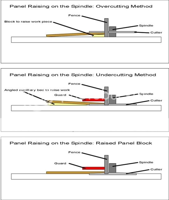
I had a visitor this afternoon who prompted me about how the cutter over panel was normally done (because I had forgotten - even though I;d been shown I've never used it in anger). The technique was to clamp a batten onto the table next to the fence and then use a grooving saw or slotting cutter to cut the panel which would by now be at an angle. This technique (top in the attached diagram) was sometimes prone to kickback as well as being difficult to guard. I was taught the second (middle) technique where an angled auxilliary bed was made on the thicknesser to tilt the work, although I rarely used it as raised panel cutters which featured a profile cutter and allowing much more ornate panels started to come in in the early 1980s (lowest illustration). These are somewhat somewhat safer to use as well as being quite easy to guard properly
Scrit
So the parallel edge ( you get this like it or not with most horizontal or vertical routing cutters) is the way to go which allows free unrestricted movement. The tapered edge clearly works but with a higher risk of failure, eg dry wood panel fitted in the winter (low humidity) The only reason I ask this is a friend is doing some work with fielded panels. I also think an exposed part of the parallel section looks more attractive IMO.
Perhaps if he would tell us how he raises panels, I might do just that......JFC":2bprysqa said:Now now Scrit i think you should take Sim's advice on this matter . :wink:
A
Anonymous
Guest
Flat fielded (tapered) panel dead easy vertically on the TS - and safe enough for Scrit if you do it properly:
Tall false fence with the bottom cut away to allow the triangular scrap piece to fall away without jamming, and tall to support the panel without wobbling.
Top of sawblade hidden under this fence.
Zero clearance insert so that thin edge of panel doesn't drop down the hole - you fix the insert in and then wind up the blade to cut it's way through.
Shaw guard or some other sprung fence arrangement to hold panel to fence and to completely cover the blade.
Safe - you can't touch the blade. Fast and neat with a good blade and firm holding. Cross grain ends first then lengths second.
You could raise a panel too by passing it face down over the blade - also can be made safe with a bit of sense.
cheers
Jacob
That's similar to making the cut on a rip saw with a canting rip fence. As you say the main thing is to get some side pressure on the board and support the bottom edge. The downside to using a vertical jig is always going to be that it can be a bit awkward to field the tops and bottoms of tall, narrow panels. On a spindle the work is run through flat and is therefore more stable. Short edges can be fed through using a sacrificial square cut backer board
Scrit
Scrit
Similar threads
- Replies
- 3
- Views
- 1K
- Replies
- 8
- Views
- 2K