Pump voltage

UKworkshop.co.uk

Help Support UKworkshop.co.uk:

This site may earn a commission from merchant affiliate links, including eBay, Amazon, and others.

Sheptonphil

Scrumpy junkie
Joined
29 Dec 2012
Messages
1,284
Reaction score
456
Location
Somerset
to those who know about motors.

when a motor is listed as three phase, 230/400v does that mean it must be three phase supply for either 230 or 400 volts, or would it run on 230v single phase?

this is the motor in question

Thanks for any insight.
C4CFB2FA-1234-42C3-A04A-3280B9DFF940.jpeg
 
The motor must get 3 phase power supplied to it to run. You can use singe phase 230 to power it through a variable frequency drive (VFD). The input 230V single phase is changed in the VFD to 3 phase 230V through electronics the magic of which I couldn't begin to explain.

Pete
 
Some 3ph motors can be wired to run on 1ph, but you get a loss of power, plenty of articles online about doing this. Usually better though to either run it from 3ph, get an VFD/RPC or just sell it and buy a single phase.
 
That's a standard 3 phase motor intended for operation at 50 Hz on common typical public supplies throughout the world. The clue and answer is on the name plate. It will probably work on 60 Hz but will rotate faster and may overheat in prolonged use because the current input will alter from the ratings on the plate and the motor's capabilities.

There are three sets of identical windings in that motor and (probably, since it shows both configurations, Star or Delta), six wires in the connection box. If there are only three cables, the common, or 'star' connection will be buried internally in the mass of the windings.

It all depends on firstly the voltage of the supply, and secondly the method of connecting.

After the voltage ratings on the plate there are two symbols, first a triangle shape after 230 - 240 volts, and this indicates that the three windings are to be connected in a 'Delta' formation if your supply is at this value.
The second, the 'Y' or 'Star' formation shows that the windings are to be connected in that formation at a nominal 400 volt supply. We don't have a 230 volt, 50 Hz supply at 3 phase in the UK so it will likely be configured in Star for 400 volts.

It doesn't show the speed, or poles so we can't say how fast it will turn. As an ex-pump-motor it will likely be a 4 pole configuration, but there's only one way to find out!

From a 2008 manufacture, its electrical design probably pre-dates a lot of modern OEM supplied VFD systems, so whether it will work continuously and reliably on a VFD system is, again, a matter of experimentation.
 
The motor will not run on single phase but a VFD (commonly known as an inverter) can provide 3 phases at mains voltage i.e. 230V in the UK.
If you go down this route you will need to ensure that the links inside the junction box on the side of the motor are connected in the Delta configuration.
Very simple to do and there's usually a connection diagram inside the junction box.
As pointed out by Argus, there's no simple way to know the speed of the motor but the VFD will enable a good degree of speed control; typically it will be OK from 50% of the rated speed to 150% although much will depend upon the intended use and motor characteristics.
Duncan
 
I have a 3 phase 1kw pump running on single phase purely by adding a capacitor to one of the phases. I have heard that this is a bad idea, but it seems to work - has been running for three years now without a hitch. I would be interested to hear from those who know why it is such such a bad idea - it is the standard way to wire pumps in these parts, which doesn't mean it is a good thing - just "normal".
 
Thanks for all the replies.

I think the way to go then is a VFD to churn out three phase. I don’t need reverse or speed control, full speed, whatever that ends up being, is perfectly adequate. It is a water pump and will be used to pump water to an irrigation sprinkler. The motor is rated as continuous use but will have little stress on it anyway. New, the pump is £1000 but this one is sub £100 if I want it. Even with a VFD at £60–70 it’s going to be a very cost effective solution. When I get hold of it I’ll post pics of the connections box For further advice.
 
I have a 3 phase 1kw pump running on single phase purely by adding a capacitor to one of the phases. I have heard that this is a bad idea, but it seems to work - has been running for three years now without a hitch. I would be interested to hear from those who know why it is such such a bad idea - it is the standard way to wire pumps in these parts, which doesn't mean it is a good thing - just "normal".
That may also be worth a try, it’s not going to be a great loss if it all goes belly up for what I’m paying for the pump.
 
You’ll need an inverter higher rated than your pump max of 2.34kw, looks like 3kw is the next one, I can’t see a 2.5kw. Looks like this will set you back £130ish for a basic Chinese import.

I’ve used Huanyang ones for a few years with no issues. Your only difference may be that you’ll be running the unit for longer time periods than most of us, so our experience could be less valid.

@Trainee neophyte my understanding is there is no issue with the capacitor/false phase method it’s just that you loose power.
 
The little triangle (Delta) and the Y (Star) are the two ways the three phases can be supplied to the motor windings. In Delta you can use a ~230V supply (but it must still be three phase). If you open that box you'll see there should be three terminals (possibly marked L1 L2 L3) and there will usually be a diagram showing how to connect the three U, V, W power lines coming from your supply (in either Delta or Star).

Like Fitzroy, I've have several of the Huanyang VFDs and have run them for years without problems, and one of those would give you a 3 phase (U, V, W) output from a single phase mains supply. FYI if the pump runs backwards then just swap any two of the U, V, W lines and that'll fix it.

Note that the Huanyang VFDs don't usually appear to have the input and output Earth terminals connected, so make sure to wire the motor's earth terminal through the VFD to your mains earth.

Note that you can configure the ramp up and ramp down times on the VFD; as inrush current can be quite high it would probably be a good idea to set a ramp up time of at least 1s as that'll reduce the draw and prevent you from popping a 13A fuse. I have a 12" table saw, 12" planer, and CNC spindle (all 3hp (2.2kW)) all running from separate VFDs and with a slow ramp up time I've never had a problem with blowing a fuse or tripping a breaker.
 
Well, after the advice offered here, I purchased the pump for £25 plus £9 courier. It’s a beast at 25kg. I bought the VFD and took the connector plate off the pump terminal housing. The terminals were connected along the top row in the star arrangement. Taking the links off and putting the as per diagram for delta mode I addded the UVW wires from the VFD.

set VFD parameters to 50Hz, 2 pole, 2850 revs, as lowara’s data sheet.

Powered VFD up, turned dial and Yey! Motor not only turned, but in the correct direction first time. It accelerates to full speed over four or five seconds and I’ve cut the deceleration time to two seconds. This means the startup current is not a massive load and the water will build pressure over those few seconds.
just got to install a 5000l tank and plumb it in to the travelling irrigation system. At least with this system I have the option to reduce flow by valve or motor speed if it delivers too much water. It’s rated at 210l/m I probably only need a little over a third of that. Not sure which way is the best to control flow to impact less on the motor or VFD if indeed it makes any difference to stress. The motor will need to be run for one hour at a time, perhaps twice a week in the dry weather, nothing in the wet.

Full speed at reduced flow, or reduced speed at full flow, which would you say is better?

Without this thread I wouldn’t have dared try this as a viable project, so thanks for all the replies and offers of help.

i believe the wiring diagram in the lid shows the motor at 230v single phase capable, but unsure what the other symbols mean on that diagram.

5A77F481-8062-4544-881D-1107A95C5E17.jpeg
CBE7B2D7-25A8-42B4-9435-7C29FA62F6F4.jpeg


wiring diagram for single phase 230v?

40883D16-2AE1-4FFB-A148-4CF02B9A8556.jpeg
 
Last edited:
Great progress! Running the pump full whack and throttling the outlet flow will put the most load on everything and waste lots of power. Running the pump at very low speed will drop the torque on the motor and you may find it stalls. I’d start by dropping the flow as far as possible with speed control, if you get to the flow you need and it’s all stable (no surging flow or pump noise) you’re golden. If not then speed up a little, close the outlet valve a little, repeat to get the flow you need.
Never throttle (close a valve partially) on the inlet to the pump, you risk cavitation and pump failure.
Fitz.
Thanks Fitz

when I get the tank installed ill Play with pump speed first as suggested. I do see there is some sort of torque adjustment in the VFD settings as well. I’ll leave them alone till I see effect of what I’ve got. It’ll be used to water our bowls green through a Leader 25/50 system which we have just acquired.

this will mean it will only talk an hour to water the green instead of six hours with our old system. We are not in a position to buy a £15000 automatic system many greens have installed.

AD14CE9F-A5AD-4193-B81A-6A5308540722.jpeg
 
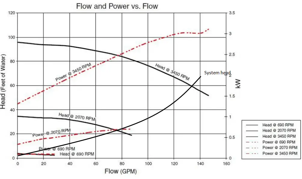
Is it a standard centrifugal pump? They use less power when there is a high head (or a semi - closed valve, which is the same thing). Frankly I find the whole thing counterintuitive and generally mystical.

performace-curve-brake-horsepower-min.png


https://www.nuclear-power.com/nucle...entrifugal-pumps/pump-head-performance-curve/

For a fixed speed, the power requirement is a function of the head developed and the flowrate. In theory the power should drop to zero at zero flow and also at zero head. Power = head x flow x density x gravity, set any one to zero and the power is zero. It will then go through a maximum power at some point between these two zeros depending on the pump's curve. In practice there will be internal recycles of flow and other inefficiencies that mean the power will never drop to zero at zero flow, and the pump efficiency will be maximal at some point, all this leads to the power curve on the graph above which is determined by physical testing. Also if you are putting 1.5kw into a zero flowrate then the fluid inside the pump heats up pretty quick ;)

However you can also see the power is dramatically reduced at the lower speed, as is the flowrate and head. You can also identify that the pump will not run above c.75gpm at 2070 RPM and c.5pgm at 690rpm as this is the intersection of the pump curve and system curve at those speeds.

Gotta love a pump curve diagram.

Fitz
Way over my head I’m afraid. 🤷🏼‍♂️🤷🏼

I just take advice and use it on something like this.

thanks though Fitz
 
The diagrams are cast into the box lid
Your motor is 3 phase so only those diagrams match
If you had a single phase motor you would use those diagrams
Ian
Kinda makes sense, it’s just it had the six contacts shown connected by something marked MP in circuit.
 

Latest posts

Back
Top