bp122
Expert at Jibber-Jabber
Hello everyone
I apologize for being absent over the past few months - work, family, cricket etc just hogged up all my time.
I shall shamelessly get to the point of requiring suggestions and knowledge.
I have FINALLY found some time to work on my MFT Router table. I already have a bonded 25mm MRMDF top cut to size and I am going to mount that on the existing base.
What needs doing?
1. Mark and cut the position of the router plate (already have a jig ready)
2. Mark and route a channel to fit the Jessem mitre track
3. Mark and make the MFT holes using the UJK parf guide.
4. Mark and cut Matchfit dovetail grooves AFTER making the hardwood edging for the table top.
What am I going for?
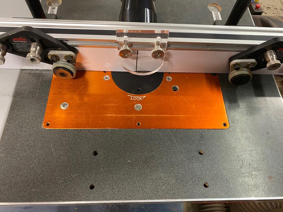
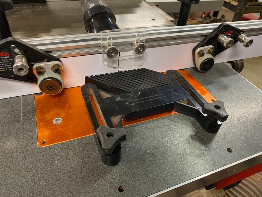
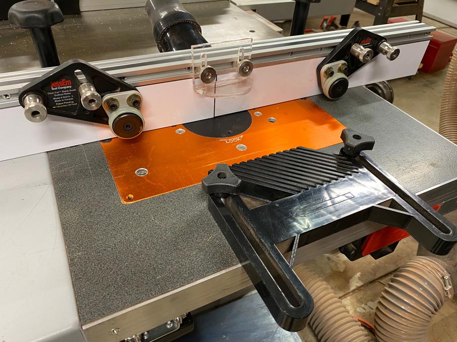
I have seen a number of router tables, but the one that I found that might suit my needs is the one on Hooked on Wood (minus the incra fence) which looks like this:

The fence will be a quickly removable one that uses the mft holes to locate - still to be designed.
Even most other tables such as incra and UJK that I have seen have the router plate offset to one side (or the tables are very small) and have the mitre track on the shorter side (see below)

I am also planning on using Matchfit dovetail grooves for overall clamping and assembly convenience (see image below)

What am I confused about?
1. Does this kind of setup shown in the first image hinder routing the shorter edge of a long workpiece (say, creating a tenon on the end of a long stretcher, workbench legs) using a mitre fence?
2. Is there an obvious reason I am missing why most router tables have the mitre track on the shorter end (B side of the router meridian shown in the sketch below)?
3. Is it better having the mitre track on the other side of the router plate (A side of the router meridian shown in the sketch below) if I am going to be using the table predominantly facing the longer edge of the table as shown in the illustration below? (Position 1 gives me more MFT space, however, in my limited thinking I feel position 2 gives me better usability of the table overall)
4. As I shared earlier, I plan to use the MFT holes on most of the table surface but also criss-cross it with Matchfit dovetail grooves - Is this a terrible idea / overkill / sensible? - Has anyone on here done anything like this that I can ask for your experience?
5. Has anyone used the Matchfit dovetail tracks as a mitre track for a table mounted router?

Position 1 shows the conventional mitre track position.
Position 2 is my proposed position for the mitre track
The top end of the table is against a wall, even though the router table can be moved as it is on castors, this will be the position it will remain for majority of the time.
On the right hand side of the table is a door into the house, so technically I can stand and use the router by standing there (hence the dotted user figure), but I'd prefer to use the router facing the long edge.
Apologies for the long post, but I'd really appreciate a response. Please let me know if my questions are confusing
Best,
bp
I apologize for being absent over the past few months - work, family, cricket etc just hogged up all my time.
I shall shamelessly get to the point of requiring suggestions and knowledge.
I have FINALLY found some time to work on my MFT Router table. I already have a bonded 25mm MRMDF top cut to size and I am going to mount that on the existing base.
What needs doing?
1. Mark and cut the position of the router plate (already have a jig ready)
2. Mark and route a channel to fit the Jessem mitre track
3. Mark and make the MFT holes using the UJK parf guide.
4. Mark and cut Matchfit dovetail grooves AFTER making the hardwood edging for the table top.
What am I going for?
I have seen a number of router tables, but the one that I found that might suit my needs is the one on Hooked on Wood (minus the incra fence) which looks like this:

The fence will be a quickly removable one that uses the mft holes to locate - still to be designed.
Even most other tables such as incra and UJK that I have seen have the router plate offset to one side (or the tables are very small) and have the mitre track on the shorter side (see below)

I am also planning on using Matchfit dovetail grooves for overall clamping and assembly convenience (see image below)

What am I confused about?
1. Does this kind of setup shown in the first image hinder routing the shorter edge of a long workpiece (say, creating a tenon on the end of a long stretcher, workbench legs) using a mitre fence?
2. Is there an obvious reason I am missing why most router tables have the mitre track on the shorter end (B side of the router meridian shown in the sketch below)?
3. Is it better having the mitre track on the other side of the router plate (A side of the router meridian shown in the sketch below) if I am going to be using the table predominantly facing the longer edge of the table as shown in the illustration below? (Position 1 gives me more MFT space, however, in my limited thinking I feel position 2 gives me better usability of the table overall)
4. As I shared earlier, I plan to use the MFT holes on most of the table surface but also criss-cross it with Matchfit dovetail grooves - Is this a terrible idea / overkill / sensible? - Has anyone on here done anything like this that I can ask for your experience?
5. Has anyone used the Matchfit dovetail tracks as a mitre track for a table mounted router?

Position 1 shows the conventional mitre track position.
Position 2 is my proposed position for the mitre track
The top end of the table is against a wall, even though the router table can be moved as it is on castors, this will be the position it will remain for majority of the time.
On the right hand side of the table is a door into the house, so technically I can stand and use the router by standing there (hence the dotted user figure), but I'd prefer to use the router facing the long edge.
Apologies for the long post, but I'd really appreciate a response. Please let me know if my questions are confusing
Best,
bp


