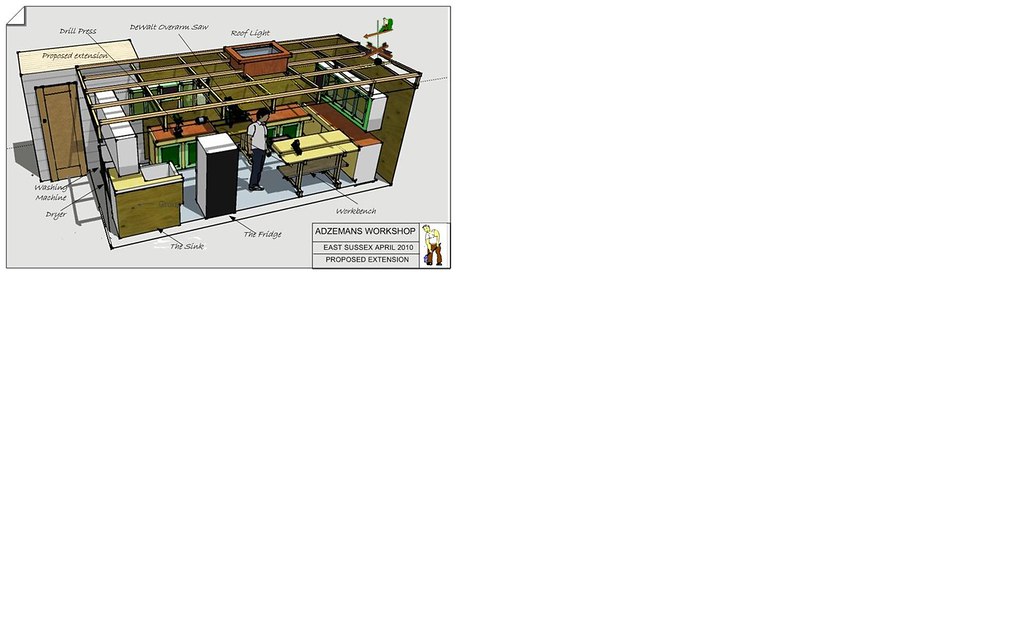
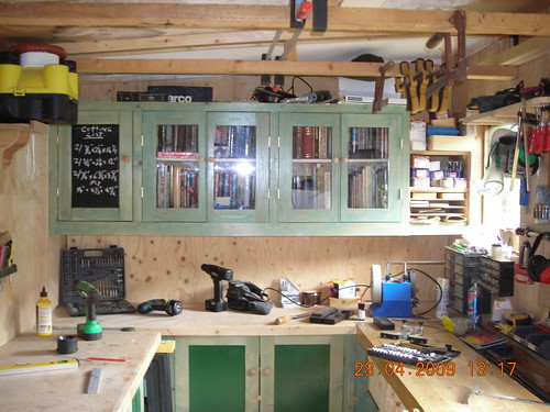
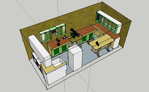
My first attempt at SU

UKworkshop.co.uk

Help Support UKworkshop.co.uk:

This site may earn a commission from merchant affiliate links, including eBay, Amazon, and others.
Another attempt at posting

Regards
4542531883_8a711deb5f_b.jpg
 
From what little can be seen in your images, it looks nice. How are you going about making the image and why is there so much white space?

As to placing components easily and accurately, that comes with learning how to use the Move tool properly. If you're importing components from the 3D Warehouse, you also need to consider that their insertion points are frequently not located to make placing them easy. You can fix that of course but sometimes it can be a big PIA. It depends upon how the person modeling the thing went about it. Very often I find it easier to draw something from scratch than to fix the models I find on the 3D Warehouse.

Out of curiosity, how big is the SKP file for this model?
 
Are you very constrained for space? The sink and the fridge are not workshop items in my view unless you are perhaps preparing biological specimens! :D
 
Thanks again for the comments.
I did this post from an internet café’ and was a bit rushed. I got the size of the picture wrong which is why I posted two pictures. The first one (small) was posted through Flicka at the usual medium size and the second at the large size. Should have re-sized the original.
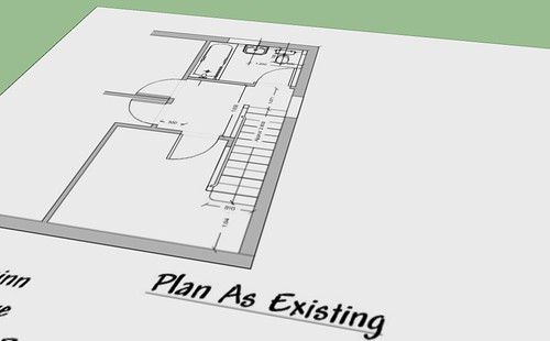
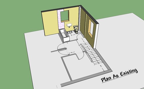
The problem occurred because I tried to put a border and title on to the drawing and for this I used CAD. Further, when I used SU to annotate the annotations did not stay with the object being annotated. More practice is required on annotation and importing CAD. It was my first attempt. I was the CAD importation that created the white areas.


4562791515_8e10ffcc24.jpg


4562790421_5bfc2526f6.jpg


The SU size is 6,194 KB I am not sure what the PIA is?

Yes I am constrained for space, I would like larger. My first home in West Yorkshire was quite large. Moving down to the South we downsized due to house value differences and then our present home is a bungalow and even smaller. The workshop was an existing 18’0” x 8’ 0” shed and stretches straight across the bottom of the garden with 2’ 6” either side. The fridge is also a freezer and quite full. The top fridge is full of beer cans not body parts!. The sink is a useful item in the workshop cleaning brushes etc or, when obtaining a cut is good for cleansing the wound. Our kitchen is too small to take the dryer so this is a compromise with my wife and the washer is temporary and will go into the garage. The dish washer is being used at my youngest daughters. I have a bench saw which is not shown here. If it was bigger SWMBO would probably put a bed down there. I manage and it’s a good retreat with either the radio or MP3 player blasting out.

I have put the workshop drawings to one side now as practice is the order of the day. I am impressed with what’s available on the 3D Warehouse and I have found deconstructing some of the models very useful and a tribute to the modellers. Yes, the intersection points are very varied and yes if I can, try to draw my own models. This leads me on to my latest training in practicing drawing buildings.
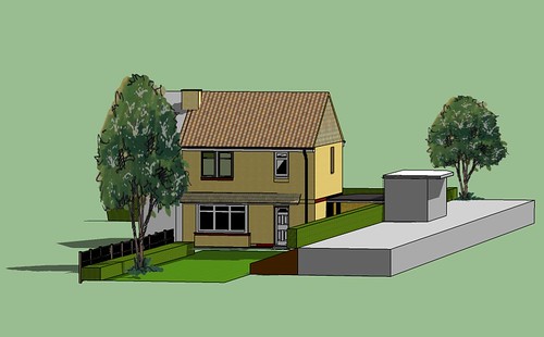
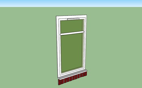
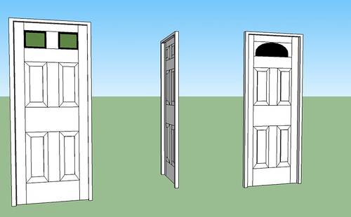
My first effort used what I call the Christmas tree method. Building up a basic model and developing the features, as you would with pencil and paper. Not to be recommended except for the most primitive drawing. What I have found is the building/object needs to be broken down into component parts and then assembled like LEGO. Decisions made to Group or make into a component. I downloaded some doors off the 3D Warehouse and struggled in adapting, sizing, positioning that I drew my own starting with the basic door. First lesson I should have grouped not as a component.
Having copied the master proceeded to change to the next style. As I changed the new model found the original master changed as well. Lesson learnt and rectified.

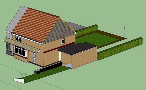
Christmas tree method


4563420700_44dda12238.jpg


Lego method

4563421904_f5e8d96385.jpg


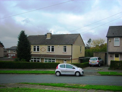
Photo of actual property

4563422014_c7324d10d4.jpg


Created models

4562791581_1de0a3619a.jpg


4562790625_383aeb94ce.jpg


A requirement now is to do the same with the door furniture.
(These are 6’ 8”, 2’ 8” doors in old money)

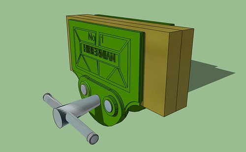
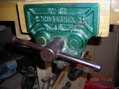
Going back to the workshop and making ones own components here is one of my vice which I did last night including a photo as a comparison? (took about 2 Hours)


4563421780_816fbec638.jpg


photo of vice

4563421194_d626db5813.jpg


Regards
 
Mike,
I may be misinterpreting what you are saying but to use your terminology, I think the Christmas tree method should not be overlooked - I suggest you look at DaveR's stuff on the Taunton site wrt drawing components in situ. it's more accurate and faster than the Lego method for most purposes.

I started with the Lego method having come to SU from a history based solids modeller and in fact this background kept me away from SU until I made a real effort to learn it
 
" First lesson I should have grouped not as a component. "

Please explain. I've been using SketchUp for more than six years and have never found a single good reason to use a group instead of a component.

Chris, thank you.
 
Ok, well I really don't get the difference between Christmas Tree and Lego?? Can someone explain?
 
Tom,
Say you want to draw a table with four legs, rails joining them and a top.

Lego:
Draw one leg, make three copies and place them as intended for the table
Draw - separate from the legs - a couple of rails (assuming the table is rectangular and not square), copy them and then place them where they are supposed to go
Draw the top and place that.

Each placement of the various components requires use of the move tool (and you can bet that the component axes will become muddled in the process of creating and placing the separate components!) Also, you have had to be sure that the dimensions of the various components conform to the intended design in some way. With a complex model, this can result in lots of tape measure/dimensioning work.

Xmas tree:

Draw one leg, MIRROR it to the four corners.
Draw one rail in situ between a pair of legs. MIRROR it to the opposite side. If the table is square, ROTATE copy it to the next position etc.
Draw a rectangle or square on top of the legs, Push/Pull to thickness and scale to final size.

This is quicker, easier and ensures component axes are in the proper places.


NOTE: I am assuming that the terms Lego and xmas tree apply here - I didn't invent them(!) however, the two different methods are what people commonly adopt.

I started with the xmas tree method but in total ignorance of the way geometry was handled in SU and thus ended up as most beginners do with all sorts of crap that got connected and shouldn't be, etc.etc. Then I learnt about components and went overboard drawing each as a library of bits that I had to assemble into the final model. I did this for far too long.

Then I learnt how to use SU properly :lol:
 
Cheers Chris. I think I get it. The Lego method is the only way I know. I prefer it because I get to build the piece before I build it, if that makes sense. I can work out a lot of the pitfalls in a design that way.
 
Tom, building the model via the Lego method as Chris describes, is not only a lot more work, it also has the potential to allow errors to creep in to model. In my opinion, the SketchUP model is where you should be eliminating errors, not inducing them.

With the Xmas tree method, you place the first major elements, the legs in Chris's example, and fit the rest of the elements to them. If you place the legs accurately in the beginning and draw the aprons to fit between them, there is no problem with retaining accurate dimensions and you don't need to actually know a lot of the dimensions to draw those parts. You'll let SketchUp tell you those dimensions later.

The nice thing is that you can build either way as you choose.

For me, time is money now for much of the drawing I do. I need to use efficient methods to get the job done because I frequently have 3 or more jobs going at the same time with tight deadlines.
 
To be honest I'm still not clear on the difference between the two options. If I was to create a table, I would draw one leg, copy it out to the next corner, then scale it to make sure it's in the right orientation, then I'd select the two legs and copy them to make four legs, using scale again to get the right orientation. To get the rails, I would draw a rectangle between the two legs and, make it a component, pull it out to the right depth, then repeat the same copy/scale/orientation process for the rest of the rails.

I do like to draw in the joinery, as I said above, it helps me build it within the software to identify problems, not induce them. When building the actual furniture piece (not that that happens often), I would then build taking measurements from the work itself, rather than rigidly working from the sketchup drawing.
 
Tom, it sounds to me as if you're using the Xmas tree method Chris described. The Lego method is more like make the blocks and then put them all in place.

Drawing the joinery is a good idea for a number of reasons. It helps you make sure that your cutlist is telling you the real size of the parts, you can see if there are going to be conflicts that need to be dealt with (colliding tenons, for example) and it gives you an opportunity to think through the processes in the shop so you can be more efficient in your work when you get there. Drawing your model also helps you thinking about things like which order to do things in. Do you cut the tapers on the legs before or after you cut the mortises? And that sort of stuff.
 
Can't say I'd heard these terms before but I'm a tree builder :)

I like to use what I've drawn for one component as a 'former' for some of the detail on the mating part. If you don't open a component for editing you can draw over some of it with new lines and they stay on the outside ready to become a new mating component.

Using the table leg example if I drew a tenon on the end of a rail I'd use it to easily draw the mortice on the leg. To do that they need to be in the right relationship to each other not drawn separately off in space somewhere on the drawing.
 
I hadn't heard those terms before either, Robert.

The other day I helped a very nice fellow with a model he was struggling with. He had two components, one of which had a tenon on it. He was trying to cut the mating through mortice on the other piece. You could see the end of the tenon on bottom of the component receiving the mortice.

The easy way to cut the mortice would be to open the component for editing, trace the end of the tenon with the Rectangle tool and use Push/Pull to push the rectangle's face through the component. In this case though, the rectangle did not divide the bottom face into two regions so the mortice could not be made.

Close examination of the model revealed that the bottom face of the component getting the mortice was 0.004138mm away from the end of the tenon. It wasn't easily seen but it made all the difference in the world as to whether or not the rectangle was getting drawn on the face or not. It turned out the component getting the mortice was drawn separately and then moved into place and it wasn't moved correctly. In working through the drawing process, I showed how drawing the component in place on the other component eliminated that problem.
 
Thanks Chris you hit the nail on the head and described what I meant better than I did. The 1st method was a model on to which I hung components, the 2nd I grouped components together in blocks which made editing easier. I found on the first method when editing I would change somthing and then find it had altered somthing else as well.

I think you have reverted to the first method due to you becoming more skilled with Sketch Up and therefore not requiring to do much if any editing.

What I have found which is fantastic! is I have imported CAD drawings and built off them.


4579213609_f45e720762.jpg


4579205789_f1aae1e62e.jpg
 
Back
Top