Well I'm sorry Nigel, I don't think you have - on many counts

First - you haven't achieved a 10:1 - it's close at the real figure of 10.14634 but 10:1 is acheivable.
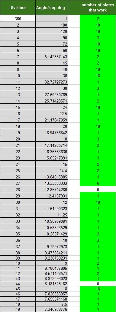
Second - you have a 41T gear in the train which is a prime number and therefore complex to manufacture needing an accurate progression of 8.780487805° between each tooth. I don't have a solution in my gear-hobber tables for 41T - but I have made one by engraving a sheet of Tufnol on my CNC machine.
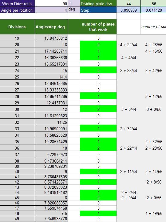
You also have a 117T and, whilst not prime, is odd with only 4 factors, needing a progression of 3.076923077° and 29T needing 12.4137931°. All OK if you have dividing plates with 29, 41 & 117 holes but again I don't have a solution for either of these; I can get 29.0013986

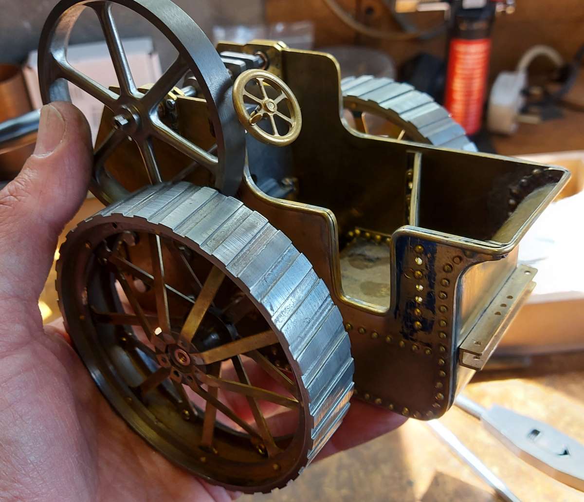
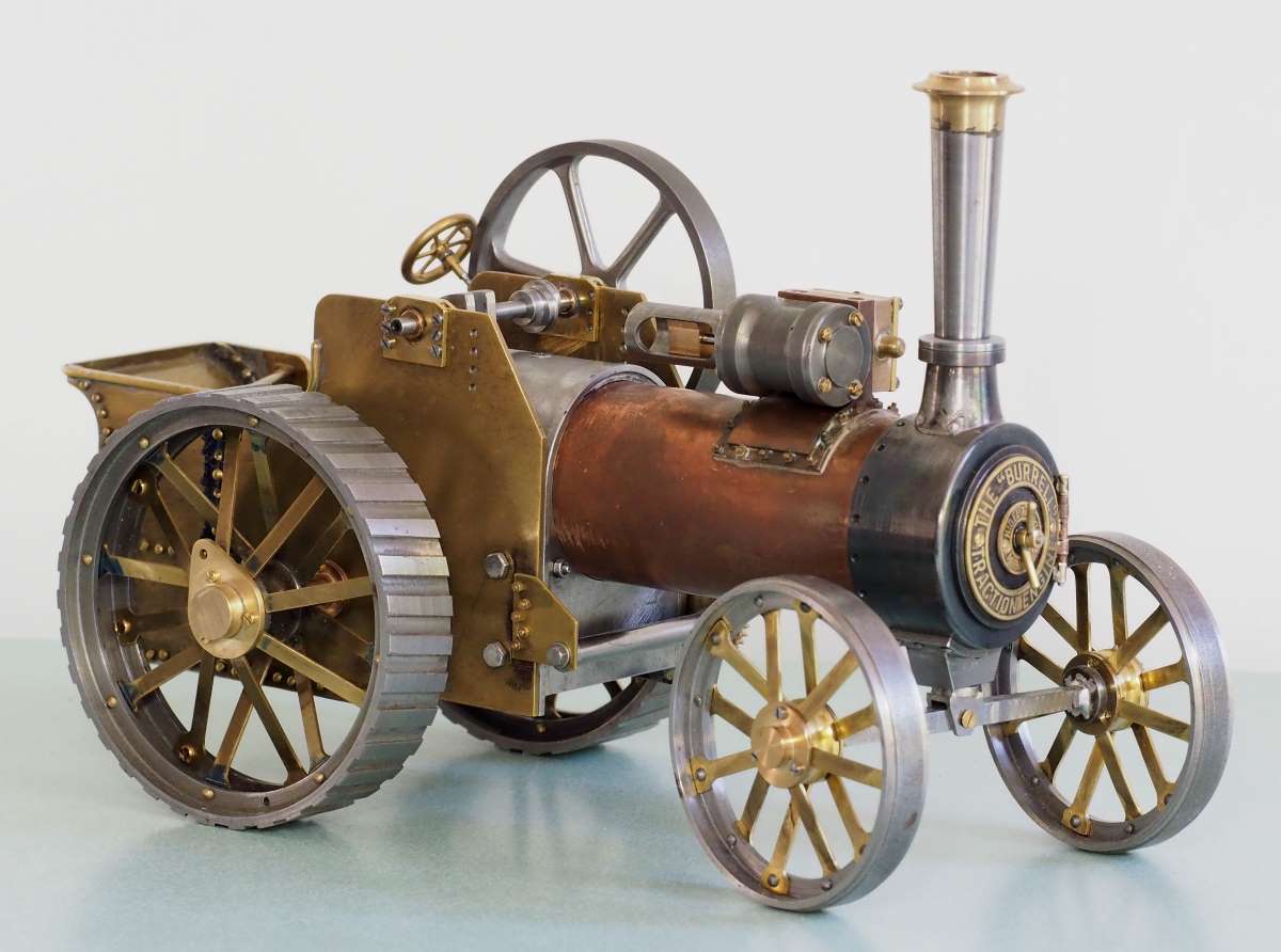
Now I must say that I think that you have done a fantastic job on this engine so I'm not decrying your efforts in any way, but there is a solution to your 10:1 which is a much better 'fit'.
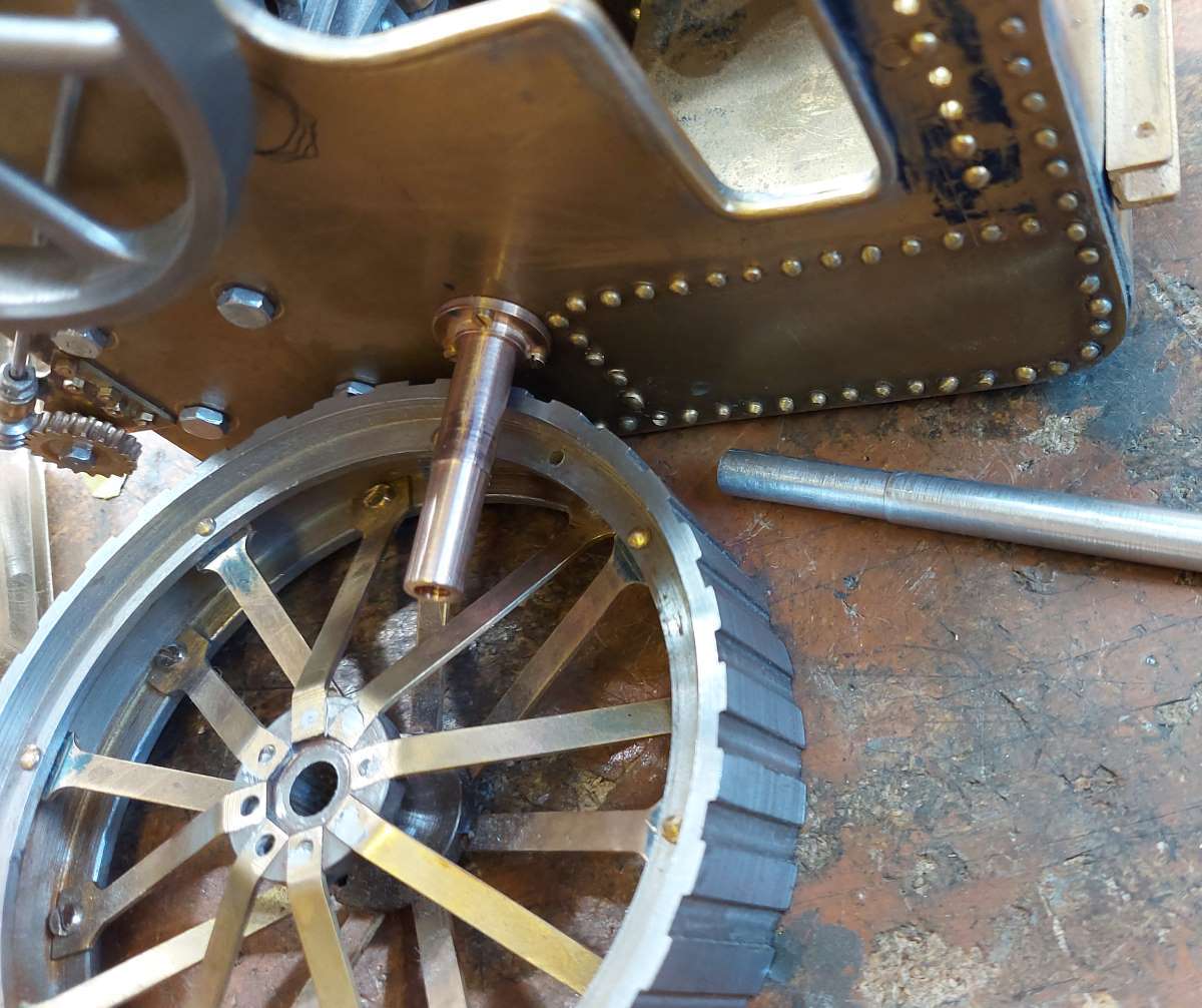
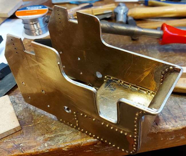
I have had to work from the photo you posted and used that to 'scale' my drawing. I have to assume that the 67.575 measurement is sacrosanct and I can only guess at the absolute centres of the two bearings from your low-res image so you will see from my drawing that I'm out on that by 0.0183mm which will have some bearing upon the dimensions for the location of the lay shaft but I doubt that they will be too significant.
View attachment 129983
This solution uses tooth counts which are easily manufactured - 25, 48, 100 & 120. Incidentally, I have used a 'clearance' - between meshing gears - of 0.1mm so the physical properties of the gears is :
View attachment 129984The 'normal' terms used to specify gear dimentions are Pitch Circle Diameter (PCD) and Outside Diameter (OD) rather than 'radius' or 'Tip diameter'. 'Centre Distance' is of course of prime importance.
I would presume that the ideal location for the layshaft would be in line with the 120T gear - which would be 90° to the bottom edge. My calculations put it at 89.48079° and to make that any more meaningful I would need very accurate information as to the precise distance between the two bearings measured parallel to the bottom edge of the Brass plate - this is the 23.2122 measurment in my drawing which is a simple scale measurment of your photo so subject to all manner of possible errors.

Changing the clearance from 0.1 to 0.2 would have a significant effect upon that angle. It may well be inconsequential but when designing clocks (or any gear train) I try to stick to easily achieved 'in-line' or 90° locations wherever possible.


