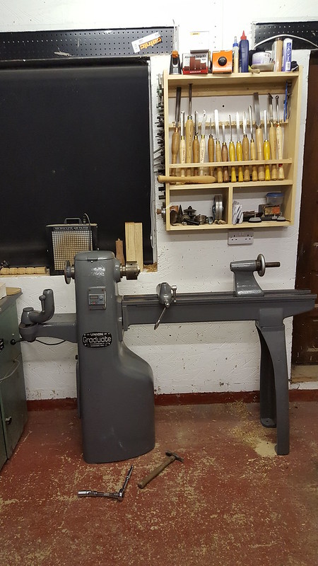
Just bought a Viceroy TDS6 short bed

UKworkshop.co.uk

Help Support UKworkshop.co.uk:

This site may earn a commission from merchant affiliate links, including eBay, Amazon, and others.
Thanks Minilathe

Unfortunately I had problems getting a modern motor with any grunt to fit in the small cabinet, hence the older motor as the form factor is smaller. A modern 1hp motor will not fit. Given its the older motor shape, it isn't actually that old, but I think it may have had a hard life as it came out of a Boxford lathe usually used for training. The viceroy comes in two cabinet sizes, I didn't think it would make much difference when I bought the lathe.

It really wasn't doing much work and bang on 50hz so normal speed when it went so unless I've got a duff VFD then I'm pretty sure the motor needs a rewind. It's a cold plate VFD and there was no heat in the heatsinks. I believe it is about 50 quid for a rewind, and given the issues I had finding a motor to fit I think I will get it done. I could always extend the cabinet but that would be a lot of messing about and ruin the aesthetics :)

Cheers
Andy
 
I hoisted the lathe off the base and took the VFD and motor to the bench.

The motor tests fine, no shorts between phases or to earth and all phases have the same resistance.

Tried the VFD on another motor. error E41 came up on the VFD - return to supplier, output probably duff. The VFD is still under warranty so sending it back for repair/replacement.

I think I have been unlucky and got a duff VFD as I haven't stressed it all. The good news is that the other motor I found, still boxed up is a 1hp, 3ph, 1430 rpm 4 pole 80 frame Crompton Parkinson motor. I can't remember buying it but it may just fit in the cabinet. It is the same shaft size as the old one, just needs the plate drilled for the B3 foot so while I have the lathe off the base I will try it for size.
 
While I'm sorting out the motor, I thought I would raise the lathe a bit. The centre was about 70mm below my elbow and it seems the preferred height is at the elbow or just above. Given I had some 50mm box section knocking about, the idea is to raise it 100mm so the centre will be about 30mm above my elbow.

Here's the box section being marked out after being cut to length.

P1070259.jpg


And a dry run before I clean up the steel for welding after cutting out the floor fixing tabs with the angle grinder

P1070260.jpg


Their will be a strip of 50mm steel above the bottom box section. Ventilation to the inside of the lathe where the VFD is located will be improved but will be underneath the lathe, 100mm off the floor and to the side so as most shavings fall to the front or back then it shouldn't mean the motor fan attracts shavings.

Cheers
Andy
 

Attachments

  • P1070259.jpg
    P1070259.jpg
    84.8 KB
  • P1070260.jpg
    P1070260.jpg
    79.5 KB
Frame marked up for welding and held in place with some mag switches

P1070262.jpg


Now painted with two coats of black smoothrite. Once this has set I will bolt the existing cast lathe base to the new base.

P1070263.jpg


So onto the pulley. Drill out to 18mm then gradually ream out to 19mm with an adjustable reamer

P1070264.jpg


Next job is not so easy, the old keyway has almost all gone now

P1070267.jpg


And it has to accommodate this key. You can see the telescopic gauges I was using to measure the bore of the pulley below it.

P1070265.jpg


The usual way is to use a broach in a mill or even a vertical drill but don't use the motor. Clamp the pulley to the table and use the quill to shave off thin 0.05mm slices at a time. You can use a lathe and put the broach in the toolpost and use the crossslide in a similar way. But I don't have the broach, I can make one but may resort to a file, but other DIY needs to be done, I shall return to this in the evening.

Cheers
Andy
 

Attachments

  • P1070262.jpg
    P1070262.jpg
    97.1 KB
  • P1070263.jpg
    P1070263.jpg
    89.8 KB
  • P1070264.jpg
    P1070264.jpg
    99.2 KB
  • P1070267.jpg
    P1070267.jpg
    72.2 KB
  • P1070265.jpg
    P1070265.jpg
    73.5 KB
Well, I nearly made a mess of that.

Don't ream the hole out like I did!

A straight cutting edge tool like adjustable reamers are no good when you have a key way. The cutting edge falls into the keyway making the tool deflect so you end up with an off centre hole. Best to use a boring bar on a lathe if possible, or at least a helical cutter.

My neighbour is tool maker and has taken it to work to sort it out. More haste less speed, lesson learned :oops:

I shall get on with mounting the new motor and swapping out the VFD.

Cheers
Andy
 
TFrench":28dtuw18 said:
Whooops! Good to know, I'd never have thought of that happening.

Hopefully this will stop somebody from suffering the same issue.

If it turns out that I have ruined it then given there isn't enough meat on the pulley to bore it put and use a taper bush, I will buy a twin pulley for about 25 quid and a taper bush to fit for about 10. As I'm running a VFD I think two ratios will be enough.

Cheers
Andy
 
The bad news was that I had bored it out about 0.5mm off centre and slightly more on the otherside as the reamer deflected. so off kilter too.

The good news is that a chap on the MIG welding forum pointed me in the direction of these, a 19mm to 24mm sleeve. This typically allows an 80 frame motor shaft to be used on a gearbox or similar that normally takes a 90 frame motor shaft but you can get other sizes.

600_RB19-24-1.jpg


As I won't have two bites of the cherry, my neighbour has taken the pulley to work to bore it out to 24mm ID and straighten in the process. I could have done it on the lathe but I'm working away plus he works as a toolmaker in the aerospace industry so a better chance of getting a good outcome :D

Once it has been bored out I need to put an 8mm keyway in it. I was going to make a tool but I thought I had better play safe, but the proper broaching tool is about 60 quid. Fortunately a neighbour needs a similar keyway cutting so we have gone halves. Still more than I wanted to spend but I intend to cut a similar keyway in a pulley for a milling machined when I increase the motor size so it just about justifies the cost.

I'm looking after the kids at the weekend so may not be this weekend that I get it all back together.

I'm making a bit of an epic out of it!

Cheers
Andy
 

Attachments

  • 600_RB19-24-1.jpg
    600_RB19-24-1.jpg
    35.6 KB
It has taken a while, I got the pulley bored out to 24mm, and I obtained a 8mm broach with a 24mm guide bush and spacers. But my fly press didn't have a stand, which is needed to push the broach through the pulley. I was sick of rigging up temporary lash ups so first make a stand.

Here's the press on the floor

P1070490.jpg


Cut up some 50mm box on the Rapidor donkey saw, I already had a sheet of 4mm steel for the top.

P1070485.jpg


Cut a hole in the top with the plasma cutter using an old shower head as a template

P1070500.jpg


Weld it up and drop the press on top with a winch

P1070508.jpg


Get the broach set up, you can see the guide bush here, it will be inside the pulley before the broach is pushed down, once the broach is all the way through you add a spacer to the bush and do it again, repeat until the keyway is deep enough

P1070522.jpg


Yippee, pulley keyway cut

P1070523.jpg


next job, insert the 6mm key into the sleeve that attaches to the motor shaft, nothing is easy on this build, the key is a couple of mm too high so I had to take it down on the milling machine, a file would have done it but the mill is quicker

P1070527.jpg


Same again but with the 8mm key that locates the sleeve hence the motor shaft to the pulley, again a bit needed taking off in the mill.

P1070528.jpg


The pulley went on with a tap of a hide mallet, not loose but not over tight. I pushed it on until the motor body is just missing the inside of the pulley.

P1070536.jpg


Next job is to bolt a mounting plate to the existing plate for the motor foot to sit on as it currently overhangs the existing plate.

Cheers
Andy
 

Attachments

  • P1070490.jpg
    P1070490.jpg
    78.8 KB
  • P1070485.jpg
    P1070485.jpg
    62.3 KB
  • P1070500.jpg
    P1070500.jpg
    73.7 KB
  • P1070508.jpg
    P1070508.jpg
    94.9 KB
  • P1070522.jpg
    P1070522.jpg
    119.7 KB
  • P1070523.jpg
    P1070523.jpg
    113.3 KB
  • P1070527.jpg
    P1070527.jpg
    81.7 KB
  • P1070528.jpg
    P1070528.jpg
    82.6 KB
  • P1070536.jpg
    P1070536.jpg
    106.8 KB
Between buying paint for the youngest's new bedroom, buying chickens, a brace of crested Legbars and a pair of Lakenvelders and walking the dog to the pub I managed to get the adapter plate completed.

I marked placed the motor on the plate in the approximate position then marked the plate up for the holes on a B frame motor which are spaced 100 x 125mm.

I drill them then countersunk them with a zero flute cobalt countersink.

P1070545.jpg


I used some M8 countersunk set screws I found in the workshop, they were galvanised and I wanted to weld them in so I don't need to remove the plate to hold the screws if I ever want to swap the motor so ground the galv off. The fumes from welding while galv is about is not good for you. I forgot to take a picture after welding but I just tacked them in and ground off any high spots so the plate sits flat

P1070546.jpg


Then bolted the motor down, I used flange nuts for this trial fit, but I will be using nyloc nuts for final fixing. I clamped the plate down in approximate position ready for the trial fit.

P1070547.jpg


Then put the motor base on the floor and lower the cabinet onto it, I'm using a pair of eye bolts in the tool rest slots to lift the machine, the bit of metal with hooks on that the slings hang off is a gadget my dad made for lifting A series engines out of minis.

P1070549.jpg


I used a 2 foot steel rule to line up the top and bottom pulleys once I was sure the bolts that hold the cabinet down are aligned. I did this several times to make sure it was spot on. Originally I was going to slot the plate so that there is some adjustment but the centre pulley location is fixed so if you line it up correctly then there is no need for further lateral adjustment.

P1070550.jpg


I marked up the plate location in relation to the base, took the motor off, selected bolt hole locations where they don't coincide with ribbing underneath the cast base or collide with the foot of the motor. I drilled the plate in the pillar drill then clamped the plate to the base and drilled through with the cordless, I'm using M8 bolts so 8.5mm holes to give a little clearance.

I gave it a second coat of Bridgeport grey when I got back from the pub. Tomorrow, with a bit of luck between painting the nippers bedroom I should be able to get the motor fitted at last :)

P1070551.jpg


Cheers
Andy
 

Attachments

  • P1070545.jpg
    P1070545.jpg
    103.8 KB
  • P1070546.jpg
    P1070546.jpg
    101.8 KB
  • P1070547.jpg
    P1070547.jpg
    118.2 KB
  • P1070549.jpg
    P1070549.jpg
    132.5 KB
  • P1070550.jpg
    P1070550.jpg
    99.3 KB
  • P1070551.jpg
    P1070551.jpg
    60.4 KB
The motor is all bolted up, tested with the VFD on the bench and on the floor ready to lower the lathe onto it.

P1070552.jpg


Once lowered onto it and bolted onto the base rather than grovelling on the floor I sat it on a low bench while still attached to the hoist. I had to change to a slightly longer lower belt and it's a pain to do but easier than being on the floor.

All in and working, note the space on the left below the pulley, this space is normally blocked by the floor but as I lifted it off the ground 100mm I purposely made sure the new base didn't block this and it's opposite number on the other side so air flow to the motor and VFD are improved.

P1070564.jpg


Close up of the WEG cold plate, passively cooled VFD and heatsink. I'll tidy the wiring up when I move onto the digital display.

P1070565.jpg


The motor spec doc for the Brook motor does not specify a clearance distance from the cooling fan, just that one is needed, however similar size/spec motors specify 50mm and there is just bang on 50mm. With the additional ventilation below I think it will be fine.

P1070566.jpg


So nearly there, while the base is on this low bench, I'll get the power cabling tidied and provide mains to the rev counter PSU.

Cheers
Andy
 

Attachments

  • P1070552.jpg
    P1070552.jpg
    93.6 KB
  • P1070564.jpg
    P1070564.jpg
    94.7 KB
  • P1070565.jpg
    P1070565.jpg
    82 KB
  • P1070566.jpg
    P1070566.jpg
    70.5 KB
Great work, tidy as always. I tried to do a rev counter on my graduate but ran into issues with interference from the VFD. Once I started using it I realised you pretty quickly get a feel for whats right speedwise, rather than having to know the exact RPM. Still be a nice feature to have though!
 
TFrench":kx2tnze1 said:
Great work, tidy as always. I tried to do a rev counter on my graduate but ran into issues with interference from the VFD. Once I started using it I realised you pretty quickly get a feel for whats right speedwise, rather than having to know the exact RPM. Still be a nice feature to have though!

Thanks :) I had something similar on the Colchester lathe but a smoothing capacitor on the power supply fixed it, but there was no VFD on that, could have been the motor. I shall have to remember to use screened cable, It's going into a die cast box that may help.
 
I used an old power supply off of a set of PC speakers to test the tacho today, it worked fine so have set about fitting it. I just put the magnet
on the shaft, set the lathe going to what I thought was about 300 rpm and moved the sensor towards it. It worked a treat. Here's the wiring diagram that I put together as the diagram that comes with it is useless.

tacho wiring mk2.jpg


The first problem was mounting the magnet, if the magnet was glued to the base of the pulley then there isn't enough length on the sensor to reach it. So instead I got a small piece of aluminium angle and glued the magnet to that then to the outside of the pulley. It weighs 4 grammes total, so not a lot of imbalance, I can always put 4 grammes on the opposite side later to balance it out.

I glued it with little bit of epoxy after making sure the location was free of dirt and oil.

P1070568.jpg


The sensor went through the back plate and was adjusted to leave a few mm gap.

P1070570.jpg


Finally I cut out the die cast box that the display will go into and drilled it for the mounting holes and gave it a spray.

P1070569.jpg


Once dry the box will be mounted to the rear of the lathe , you will see later.

Cheers
Andy
 

Attachments

  • tacho wiring mk2.jpg
    tacho wiring mk2.jpg
    21.3 KB
  • P1070568.jpg
    P1070568.jpg
    78.4 KB
  • P1070570.jpg
    P1070570.jpg
    84.6 KB
  • P1070569.jpg
    P1070569.jpg
    115.9 KB
Part two of the rev counter. it didn't take anywhere near as long as I thought it would so I finished it during tea break.

I bolted the box onto the top of the lathe at the back using the top two existing bolts that hold the top pulley cover on.

P1070579.jpg


I wired it up temporarily to test it.

P1070577.jpg


It worked a treat

P1070573.jpg


So wired it up properly and put the cover on. The power lead was going to be routed inside the lathe but on second thoughts the steel/iron body of the lathe is a very good screen of interference from the VFD so I thought I would leave it external.

P1070580.jpg


I've ordered a 12 LED goose-neck light to fit on the bottom two screw holes of the pulley plate given that I have a 12v supply in the lathe.

Next step is to sort out the bolts, spacers and bristol levers for the tool holders and tailstock then we are done.

Cheers
Andy
 

Attachments

  • P1070579.jpg
    P1070579.jpg
    91.5 KB
  • P1070577.jpg
    P1070577.jpg
    105.2 KB
  • P1070573.jpg
    P1070573.jpg
    87.8 KB
  • P1070580.jpg
    P1070580.jpg
    80.5 KB
One of the fixings for the tool rests is completely missing and one has the knobs missing and only one of the three has a decent washer on it. I can get by and do a bit of turning but I am intent on finishing what I started.

My original plan was to make facsimiles out of stainless steel complete with new knobs, but this is not a good design for the main tool rest as the tbar bangs on the side of the lathe making it difficult to tighten, a bit of a poor design.

So I have changed tack and instead I'm using Bristol levers, some 1/2" BSW threaded rod, some spacers from a stainless steel balustrade and a length of 30mm OD aluminium rod. I couldn't find male levers threaded 1/2" BSW.

P1070583.jpg


The threaded bar will be cut into 3 and loctited into the Bristol levers. The aluminium will be cut to make 3 lengths and bored out to accept the threaded bar. The stainless spacers will be drilled out to take the rod.

Although the spacer is the same OD as the original washer, or at least I think it is the original, it is fine for the outboard tool rest and tailstock, but is slightly too large for the main tool rest. Here's the "original" washer next to the new, along with the only complete T-Bar.

P1070586.jpg


Outboard tool rest slot with spacer in position, the hole is central in the slot

P1070584.jpg


And the main tool rest, the hole is not central as it is a bigger casting and the rim of it is thicker pushing the washer over a bit so I will need to take a few mm off the OD.

P1070585.jpg


I'll just make one complete clamps to begin with, see how I like it then make any improvements, I may end up using the existing complete T-bar for the tailstock and the Bristol levers for the tool rests, I shall see.

Cheers
Andy
 

Attachments

  • P1070583.jpg
    P1070583.jpg
    70.7 KB
  • P1070584.jpg
    P1070584.jpg
    53.3 KB
  • P1070586.jpg
    P1070586.jpg
    76.7 KB
  • P1070585.jpg
    P1070585.jpg
    48.9 KB
The wife is away on a permaculture training course for six days so I took the day off as there was loads to do. Unfortunately none of it workshop based, but I did get 40 minutes later on after the kids went to bed.

I made a prototype clamp with the spacer 60mm long, the lever was far better than the existing T-bar. I adjusted the length to 53mm as I have a 3 x 100mm threaded studs and I needed a bit more visible thread and at that length the levers still miss the apron on the castings.

So while I had the drill in the tailstock and the parting tool in the toolpost I bored out two more and parted them off at 53mm.

P1070588.jpg


If I get 10 minutes tomorrow I will chamfer the edges and etch prime the spacers. I have sourced some 40mm OD stainless washers for the top which should be here next week so by then I will have the spacers painted then I can finish the lathe and finish the bowl I started before the motor died.

P1070590.jpg


Cheers
Andy
 

Attachments

  • P1070588.jpg
    P1070588.jpg
    108.2 KB
  • P1070590.jpg
    P1070590.jpg
    84.4 KB
I managed to get the spacers chamfered in the lathe then a light rub down and degrease and a coat of etch primer on Saturday and yesterday I gave them a coat of blue hammered finish to match the rest.

Today I only had time to assemble them and use Loctite thread locker on the levers.

P1070591.jpg


I also painted the tailstock hand wheel at the weekend.

P1070592.jpg


Once then 40mm OD stainless washers arrive for the clamps I will fit them and bolt the lathe to the floor, then that is about it for now. I may reinstate the contactor and fit the emergency stop button at some point but I need to move on and finish the roubo bench and start making cabinets for the utility and kitchen soon, oh, and the daughter wants a new bed, and a desk, and a bookcase and an ensuite fitting.........
 

Attachments

  • P1070591.jpg
    P1070591.jpg
    105.1 KB
  • P1070592.jpg
    P1070592.jpg
    93.5 KB
The 40mm M12 A2 stainless washers arrived for the toolpost and tailstock clamp so it's finished, I give you the "Variable Viceroy" :)

P1070594.jpg


As you can see from the next pic, the missus bought me some more bowl blanks :D

P1070595.jpg


The swan neck 12v LED lamp arrived, this was going to be attached to the back of the box where the digital display and a 12v supply resides but I thought it would get in the way so I wired it up to the box but fitted it to the board behind the lathe. The only think remaining to do is to bolt the base down. I may tart up the floor a bit first before I do that.

I could do with a shelf for chucks, jaws and what not, I was thinking of a shelf with hole and indentations to take them securely behind the lathe but would probably get covered in shavings. I was also thinking of a chisel rack too. What do you do with these?

Cheers
Andy
 

Attachments

  • P1070594.jpg
    P1070594.jpg
    106.7 KB
  • P1070595.jpg
    P1070595.jpg
    101.2 KB
This is what I made for mine:

The chuck jaws all hang on nails in the side of the cabinet. Crude but you can see them all and they don't get covered in shavings.
 

Latest posts

Back
Top