Headstock/tailstock alignment

UKworkshop.co.uk

Help Support UKworkshop.co.uk:

This site may earn a commission from merchant affiliate links, including eBay, Amazon, and others.
Bowl turning of course has nothing to do with the bed or the tailstock. I've found the only way to perfection on the rim of a bowl is to turn the inside and outside at the same time (on a single mounting). Turn and finish the base and the side up to an inch or so of the rim then reverse it, finishing inside and outside as thin as you choose. Others may do differently, but it works for me.
If you finish the whole of the outside and leave the bowl even overnight before working the inside you may find it has distorted enough to give that deviation or even more.
 
Last edited:
I suspect that the lathe bed has some twist in it. It may be that the lathe wasn't leveled when first installed & not noticed until now or perhaps the lathe has moved from its original spot. Even if this is not the case it won't do any harm to check it out.
 
You can buy a double ended taper from Axminster to align the two ends before you nip up the headstock. Not sure if this would solve it unless it is definitely the headstock out of alignment.

It doesn't really help as the amount of error we're talking about when the tailstock is right next to the headstock (which would be the case when using that tool) is barely even noticeable, and alignment would be forced when you attempted to clamp things down. Possibly damaging the tool, but also resulting in the tailstock now being stuck. That tool is for the case where the vertical alignment is fine, but you're just rotating the headstock into place.
 
You could possibly use a laser collimator, you would be able to pick up one off ebay for using to allign the mirrors in a telescope I'd think for about £20. Problem is that it would have a parallel shank to suit a telescope lens rather than a morse taper. It might be enough to let you know whats going on however.

Just a thought
 
How old is this ?
If it's youngish - and this may not be limited to the warranty period - take it back.
If that isn't viable and you are going to need to fix it, then you need to figure out what is happening.
You need to establish
Is the spindle off and drawing a cone ?
Is the spindle simply tilted up or down ?
If the head rotates, does the spindle stay parallel (or at a constant angle) to the bed ?
Likewise for the tailstock - is is parallel / up/down/left/right relative to the bed ?
And is it at the same centre height as the spindle ?

The double taper test bar from Axminster or elsewhere is a good start. At the least, it helps you turn the headstock into line with the tailstock (specifically at close distance - if something's off, then they will misalign as you pull the tailstock back) but it gives you something to measure the direction of the bore with
You also need a measuring gear upto the job. An engineers dial gauge and a magnetic base / arm are where I'd begin. Any model engineering friends or acquaintances you could ask to help out ?
Ultimately, use beer can shims to get it lined up and to show you how big an error is and where, Then carefully remove metal from the opposing points to realign permanently. Not an especially easy job but you may get close enough with a few shims that you can live with that.
 
If it were mine I would measure the ring the headstock spins on to make sure the surfaces were parallel, thicknesses at several points with a micrometer. Then clamp he headstock with ring in it to as flat a surface as you can find, ideally a granite surface plate or table but a granite counter top, thick plate glass, cast aluminium tooling plate, largish milling machine table etc. Put the test bar linked earlier in the morse taper and check that it is parallel to the surface you clamped to. Rotate the ring 90º and repeat the measurement. In a pinch you could use a straight edge and measure to it. That will tell you if the bore the ring sits in is perpendicular to the bore of the spindle. If it is then you need to establish if the bed of the lathe is machined flat, ideally with a surface plate but a straight edge will work in a pinch. Sit the bed machined surface down on the surface plate and use feeler gauges to measure the gaps. Or use the same method with the straight edge. Ideally the straight edge would be the calibrated steel or cast ones made for the purpose but a good quality level like a Stabila would do. The biggest stumbling block for what I have described is going to be finding a flat surface to work off of.

With all the tools available with my last job I would have put it on a CMM (Coordinate Measuring Machine) and measured the heck out of it but with home CNC milling machines becoming more popular it could be probed on one of them. So if you do have a buddy with one you could enlist their help.

Pete

...I think sometimes people forget that some of us are just woodturners in a little shed out back ;)
 
Last edited:
Ultimately, use beer can shims to get it lined up and to show you how big an error is and where, Then carefully remove metal from the opposing points to realign permanently. Not an especially easy job but you may get close enough with a few shims that you can live with that.

It's about 20 years old.

My plan is to use the test bar mentioned by musicman.

Either this or this (thoughts?). The ones from ebay seem to all come from India and will take a month or so.

I'll put it in the headstock, and then add some shims on the machined ring (under the headstock, see previous pictures) until the point in the tail stock aligns with the hole in the end of the test bar. Once I get it right, I'll then slide the configuration up and down the lathe to make sure it's correct in different places on the bed. Although to be honest, I never move the head stock, just rotate it. So as long as the alignment is ok for the first ~500mm. I'll be happy

... until I need to do something longer that is. :)

It's going to be a royal pain in the arse no doubt.
 
Last edited:
The procedure is exactly the same as for a metal working lathe. Mount a test bar in the headstock centre. Now use a dti mounted on your rest so it bears directly down on top of the test bar. Now take a measurement at the far end of the bar, and then slide the toolpost along the bed so the dti runs along the top of the bar until it is just in front of the nose of the spindle. The difference between the two readings will tell you if the spindle is not parallel to the bed. You can check if the bed itself is bowed using a large framing square or a long straight edge, a steel rule will do provided it's long enough. An error of the size we are talking about here will show up very easily.
 
If you know what taper test bar you need why not ask on the metalworking forum. There might be someone near you who would lend you one, and maybe a dti if you haven't got one. Anyone who is familiar with setting up a metal working lathe will be used to measuring this sort of thing to within a few ten thousandths of an inch. Don't know what level of accuracy you need on a wood lathe, I would have thought maybe a few thousandths would be acceptable. That should be quite easy to achieve. Very important not to assume anything until you have some accurate measurements, otherwise you risk adjusting things that weren't actually out in the first place.
 
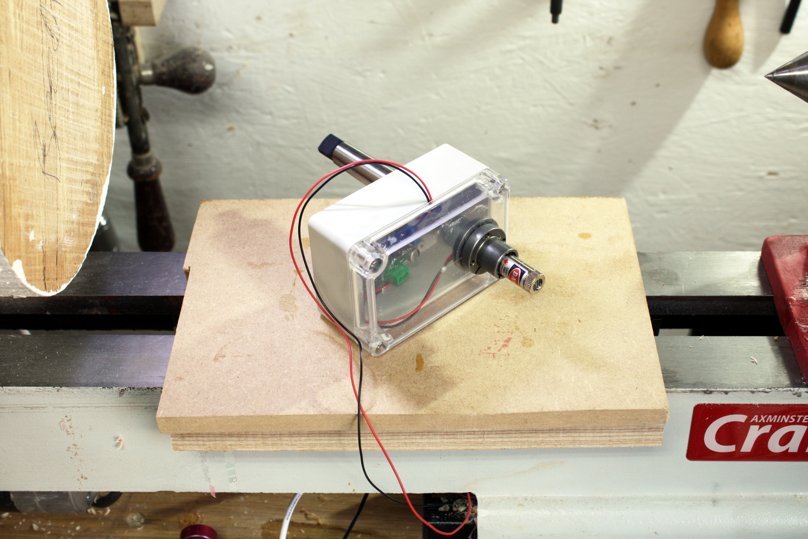
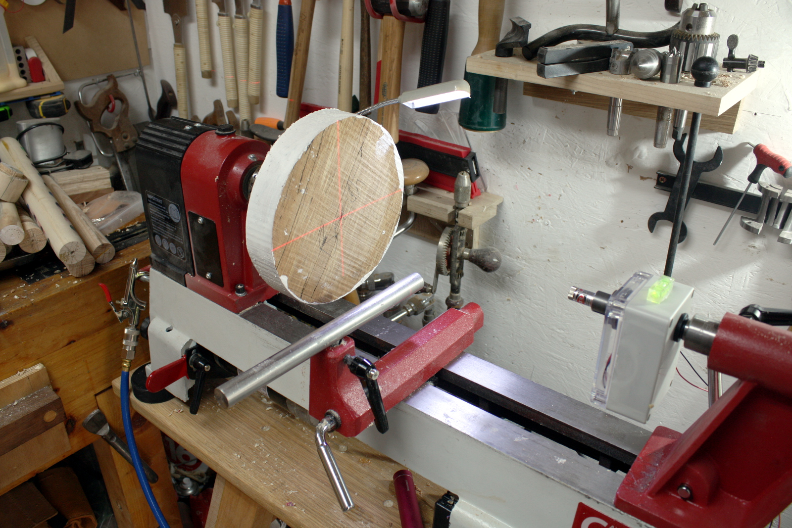
Or just stick a laser on an MT2 taper in the tailstock and align visually from either end of the bed:
IMG_4353a.jpg

IMG_4358a.jpg


But I'd have thought the double-ended MT2 alignment tool would have been sufficient for most of us. TIL!
 
I am a bit late to the party but check under both the head and tail stocks for a build up of wood dust and oil which affected my lathe alignment.
 
1st things first, clean all the crud from all machined surfaces, back to clean metal.
Take a flat oil stone, and rub gently over all the machined surfaces, looking for high spots, usually caused by dinks and bumps during assembly, the idea is to remove the moved metal, which will show up as shiny flecks.
Reassemble and check all alignments.

Bod
 
For my money I comment
1. make sure the lathe bed is not under tension/out of fully square perhaps caused by one or more legs being bolted harder to the floor than the others, and also ensure the bed has been set up horizontal.
2. Shim the headstock (flattened beer tins work well) and using one of the MT2 Lathe adjustment tools (taper fits in both headstock and tail) you will be able to get the shim thickness and all aligning properly
3. With the known amount of shim thickness you can remove/replace as you wish.
4. When not working between centres the shimming or not is irrelevant.
 
#55, Hi Mark, is that a constant current source in that box for the laser?, i skimmed the the last 3 pages, may have missed the text..
 
If it were metal it would be an issue but wood is flexible so that as the jaws of the chuck close the wood crushes differentially and moves the piece. Put the tenon in the chuck (the shoulders should be up against the lips of the jaws and not bottom out on the chuck). Bring up your tail stock to align with your dimple. Wind the live centre in to push the piece firmly into the chuck. Do up the chuck using each key hole in turn increasing pressure until they all tight. Release the tail stock if you must but don’t be disappointed if there it is still slightly misaligned. It is wood after all not bits for a jet engine.
 

Latest posts

Back
Top