CNC milling machine retrofit

UKworkshop.co.uk

Help Support UKworkshop.co.uk:

This site may earn a commission from merchant affiliate links, including eBay, Amazon, and others.

Ian Dalziel

Established Member
Joined
13 May 2004
Messages
568
Reaction score
2
Location
Scotland
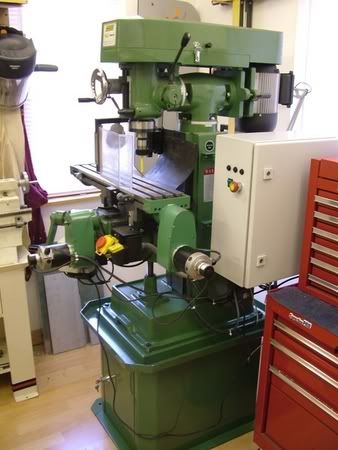
For anyone interested….i will be converting my new milling machine to cnc…..i have about 90% of the bits required…just awaiting a couple of things then I can get going. with advice from Kong
I will be running a project log here
http://www.cnczone.com/forums/
If you would like to see it run here as well, let me know, I’m aware that this is a woodwork forum but it might interest the odd few.
Converting a mill or building a cnc router isn’t cheap……excluding the mill I’ve spent £1680 so far and about another £200 is needed for bits and that’s before I buy software. I have tested sketchup drawings saved as dxf files and they look as if they work so hopefully wont need an expensive package but time will tell.
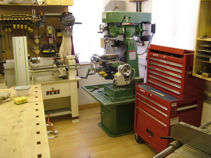
DSCF2012.jpg


regards

Ian
 
Ian

I will be very interested to view your progress, even on this forum. I suspect that many of the techniques used would be equally applicable to , for example, a CNC router. I have recently left a a job where the last year in particular was spent using CNC routers - amazing things! I must confess I hanker for a CNC mill or router. In my limited experience, its the software which makes or breaks the set up so I will be very interested in your observations

What name will you be using on the other forum?

Bob
 
GCR,

Just home...will be progressing things over the next couple of weeks.

It'll be in the Milling machine project log.

The reason i am doing a mill retrofit is i want to make a few more handplanes in particular Holteys 98. I opted for a knee type mill which
allows for a good distance between table and quill and i intend to fit a PC690 router motor body to allow me to rout wood if the need arises.
this way i get the best of both worlds..

Ian
 
Finally made a start,
Been busy over the weekend building the control panel. Man its hot over here in the UK, not used to this heat.
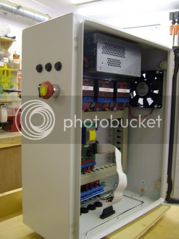
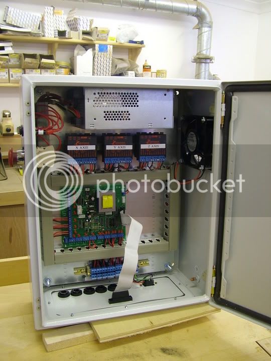
The control box is a Rittal AE series….size is 400mm x 500mm x 210mm deep. I used a Lambda PSU….part no sws600 which is a 24v dc output.. 25amp. The gecko drives are mounted onto 12v heatsinks and fans. I used a thin piece of metal din rail to bridge the 3 off them together…I slackened the screws that hold the fan onto the heatsinks and slide the metal bridge across the 3 sandwiching them, then tightened the screws back up being careful not to buckle the fans. The heatsinks are then supported onto the backplate of the control panel via nylon spacer screws allowing me 15mm of back clearance.
I used the Campbell designs breakout board to link to the pc via the parallel port. Very nice board and straight forward, all clearly marked with no problems encountered
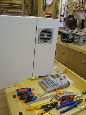
The fuses are mounted on the side of the panel as It will be getting side mounted onto the mill and gives better access. I also fitted the Estop and an on/off switch here as well.
I predrilled the baseplate ready for the motor and limit cables and have wired a separate junction block so as I don’t need to disturb any wiring.
The PSU has its own cooling fan but I also side mounted another to pull more air in…just in case…this allowed me to have the geckos mounted mid panel rather than mounting them on the sides. I used 17amp tri-rated automotive cable for the psu and to the geckos and the 240 volt circuits, this was about as heavy a cable I could wire into the geckos…the rest is 8 amp automotive cable.
The encoders will be wired direct once the control unit is mounted. As these are already shielded I didn’t want to risk any noise.

I haven’t wired the 12v heatsink fans as yet…I was toying with the idea of using the breakout boards home switch power supply to these as I wont be putting home switchs on I’m going to rely on my limit switches ????anyone any thoughts on this?

So far so good

Now to get started on the ballscrews and motor mounts

Regards

Ian

DSCF2016.jpg

DSCF2017.jpg

DSCF2014.jpg
 
Gawd Ian,

That is treble triple quadruple Dutch to me! I guess you are building the PC controller bit here?

PS. Can you please update your forum profile to include planemaking, metalworking and electronics? Your choice whether you put the word genuis after it!
 
I agree with Chris, Ian.

I can't fathom the work required. This is a very interesting thread. And besides, the CNC machine just looks cool!

Mike
 
waterhead37":1q7spee3 said:
That is treble triple quadruple Dutch to me! I guess you are building the PC controller bit

Yep its the control cabinet to control the motors that run the axis on the mill . It was double dutch to me as well a few months ago but a fair bit of studying and some help from Kong it now makes perfect sense.


i'm away to lie down my blue blood has started to go red.....way too hot for me

Ian
 
Ian

Thanks for the continuing information. Looks like you have some serious equipment installed. I assume you will need a powerful motor to raise the knee in particular?

Bob
 
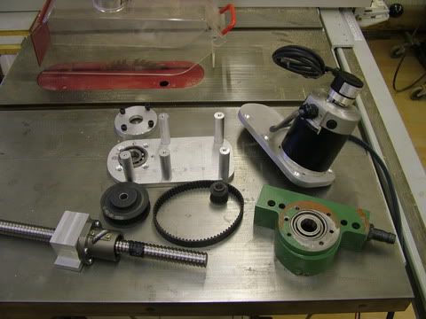
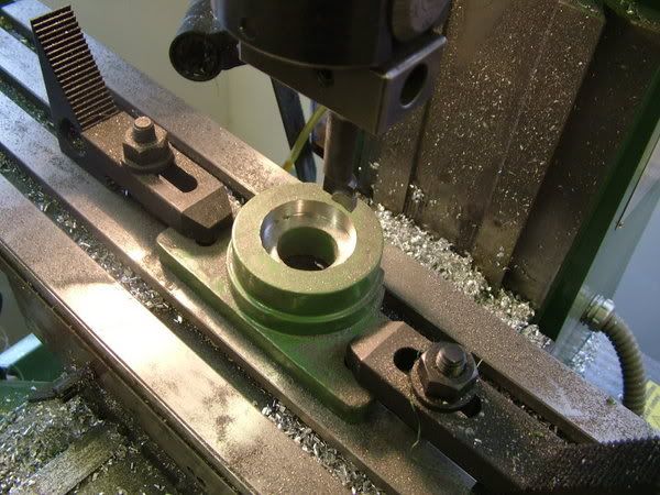
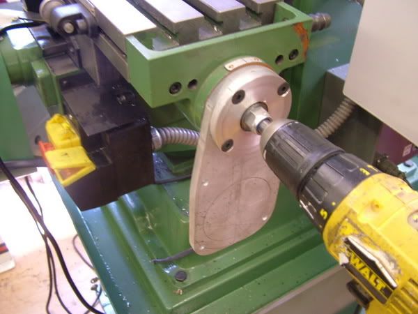
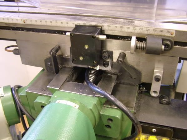
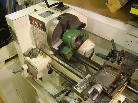
Work commitments have kept the progress slow but it is coming along. I had to bore out the original end bearing housing that’s mounted on the machine to accept the new bearings. That took ages to set up. The original bearings were 43 od and the new angular contact bearings were 47 mm od so a bit of turning was required. Not much fun on a small lathe but it managed it none the less.
.
I have tried to keep as much of the original componets intact eg although I bored out the bearing housings etc the bore of the new bearings fits the old shaft so if I ever need to revert it back again it shouldn’t be too difficult.

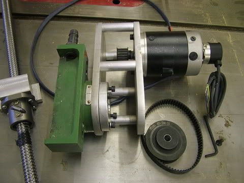
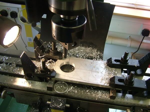
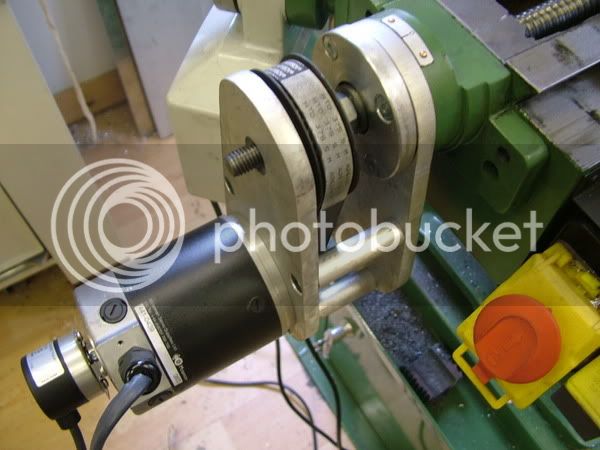
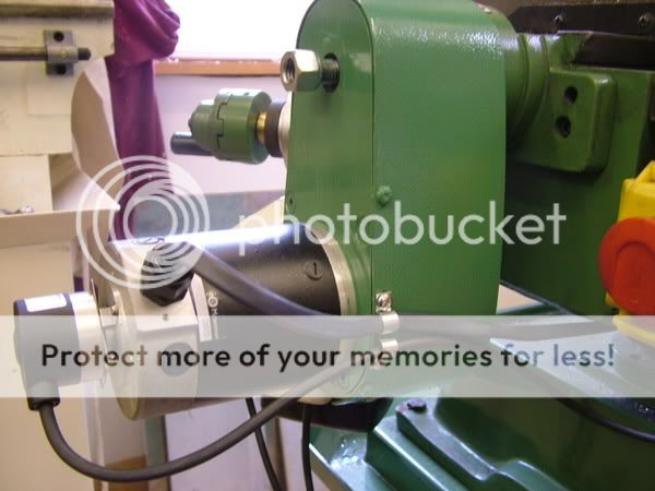
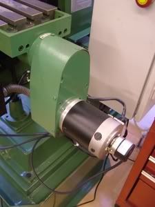
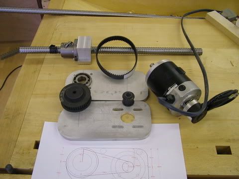
For the X axis I used 10mm aluminium plate for the motor mount flange and bearing housing flange. These are bolted onto the existing bearing flanges.. these are bolted together with 15mm aluminium bar 55mm long which I drilled and tapped at the lathe.
The motor mounts I premilled slots to allow for some adjustment on the timing belts.
I have gone for a ratio of 1---2.5 on my timing pullies. The belts are 15mm wide.

I have only managed to turn one end of the ballscrew so far. I had to cut through the hard stuff with a grinder before the lathe would turn it…I still went through a few tips though with a few sparks flying…..safety glasses a must here. I have premachined the ballscrew nut housing but haven’t as yet fitted it. There is still another nut to go onto the housing the photo only shows one nut.
Slow but steady progress

now i'm off to the sunny Algarve to spread ot like a burst mattress on the beach for the next week or so

DSCF2019.jpg

DSCF2020.jpg

DSCF2023.jpg

DSCF2028.jpg


regards

Ian
 
Ian

It does all look very exciting and I'm sure you'll be abloe to 'lose' the cost in your next commission :^o

Enjoy your holiday.

Cheers

Tim
 
Ian!
Using your Unisaw as a workbench? :shock: Horror!
Have you now converted to the "dark side" and given up on the sawdust? :wink:
Have a great holiday,
cheers
Philly :D
 
Chris,
It took over an hour to set the housing up....i used a dial indicator mounted on a mag base....slow but steady progress when turning as the cast is easy to turn...i was just a bit concerned that it would come out the chuck at me but it was fine.

Philly,
i was only photographing the bits on the saw......the bench has got a load of beautiful timber sitting on it for now, the dark side is starting to get lighter though. once the mill/routers done i'm hoping it will give me more versatility to do almost anything and make stuff thats hard to find.

i've bought a load more machines which are due today and i fly tonight, just hope i got my timings right.

Good to see Konrad Sauer comeing over for the axminster show....i'm sure everyone here will give him a warm welcome. He's going to display his works of art......Philly you should probobly leave the plastic at home :D

Ate logo

Ian
 
Bought myself a boring head….this has made life so much easier for boring awkward shaped pieces. Have been on holiday and updates have been slow but I still have a few days left to get cracking.

DSCF2227.jpg


DSCF2228.jpg


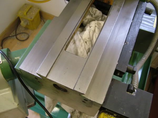
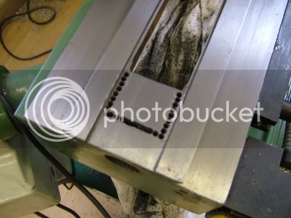
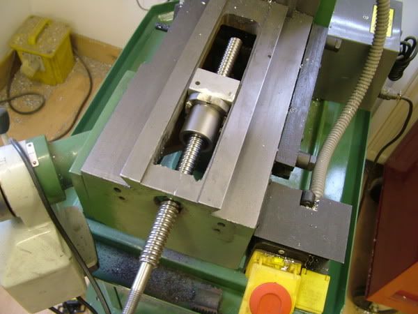
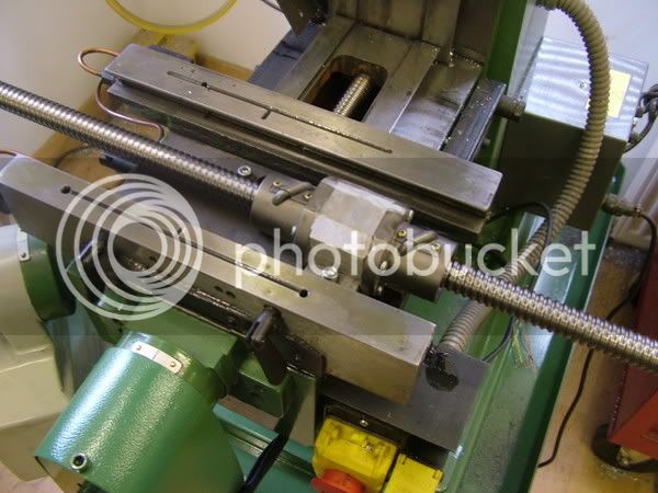
I have now completed the Y axis…..it took a bit of shoehorning to get the ballscrew nut and housing in as you can see from the photos. I had to cut away about 45mm out of the front of the knee to allow me the same travel as I had before. Wasn’t to difficult. I drilled a series of holes then carefully cut with the angle grinder then tapped with the hammer and it fell away. I also had to cut away the sides of the ballnuts slightly to make sure there was enough clearance.
DSCF2236.jpg

DSCF2238.jpg

I have tried to keep as much original parts as I can….i have rebored the original bearing housing and fitted 2 sets of angular contact bearings. The bore of the new bearings is the same as the old shaft so if it ever goes back to being a normal mill its and easy conversion back.
DSCF2241.jpg

DSCF2243.jpg

DSCF2245.jpg

I have used 20mm x 5 ballscrew…turned the ends down to 12mm and made bushings to suit my bearings
I have brought the shaft right through my motor mounting brackets as I am going to make a little bush so as to allow me to fit on the original handles in case I ever want to use the machine in manual mode..

Getting on now with the X axis shouldn’t be too long now for an update

I will also upate my site here over the next few days

Regards

Ian
 
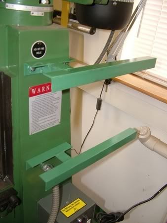
now got the machine running on the x and y axis only ….still to fit up the z axis….cant believe how accurate it is, .nice and smooth running ….I am trying to design the Z axis so that I can incorporate a router body which will allow me to cut some wood in 3D so I’m looking forward to that.

The Y axis took a bit of shoehorning to get in and I had to cut out a piece of the knee casting to allow me the travel it had originally
DSCF2248.jpg

DSCF2249.jpg

DSCF2250.jpg

DSCF2251.jpg

DSCF2255.jpg

DSCF2257.jpg


regards

Ian
 
Looks great! I didnt realise just how much space the recirculating ball screw would take up. I was also impressed by the apparent quality of the slideway surfaces - some "modern" machinery can be left in a rough state.
Bob
 
Ian, I have just got my first two issues of a new US magazine on building model engines, on the back cover is an advert for a CNC conversion for the Sherline mill, not a bad price, $1075 for all the motors etc or $1775 with computer, programmes etc. but not quite the capacity of your machine! Here is their website if you are interested.

http://www.sherline.com/CNCmenu.htm

http://www.modelenginebuilder.com/default.htm

Jason
 
Back
Top