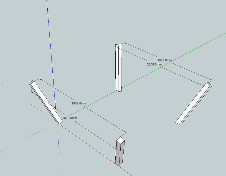
Aaaaargh, what am I doing wrong??? Please help!

UKworkshop.co.uk

Help Support UKworkshop.co.uk:

This site may earn a commission from merchant affiliate links, including eBay, Amazon, and others.
Thanks Dave

I still don't get the rotation bit (brain just isn't working today), but I think from the other answers I have worked out what the issue is.

From these pics you can see that I have decided to keep the 5deg splay on the side rails too and compensate for the angle by angling the inner rail that the slats will rest on.
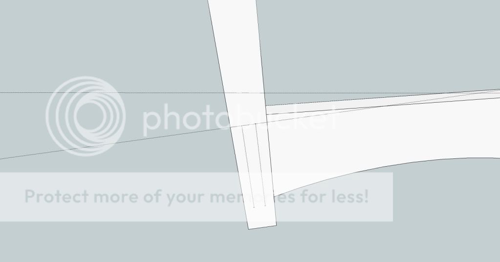
Bedrail2.jpg


As per Chris' post, because I have marked up the guide points from the bottom edge of the leg (which is obviously at a 5 deg angle) the the inside faces of the rail are higher thus bringing in the small (0.22mm) gap you can see here.

Bedrail1.jpg


In reality I don't think this tiny gap will make any difference at all to the build process but if anyone can offer a better way to do these side rails then I would be most happy. :D

Dave - As you say, when I build it I will build the head/foot boards flat and introduce the angle later, but I think I will still encounter this problem when I cant them backwards, or am I missing something (highly probable)... :oops:
 
I think you wil find it easiest if you do as Jake in fact suggested and that is to trim the feet flat with the floor after your first rotation. This will give you the correct edge to make the second rotation around.

792619353_n5XNm-L.png
 
It's the same problem as the trestle I've got here.
You have to choose between square section posts which won't project square on plan, or rhombus section posts, which will (if you've worked it out right).
Or just bodge it in the old fashioned way.
 
waterhead37":14o7yto2 said:
I think you wil find it easiest if you do as Jake in fact suggested and that is to trim the feet flat with the floor after your first rotation. This will give you the correct edge to make the second rotation around.
That's part of the problem Chris, I don't want the feet flat on the floor. I intend to have a round bun foot on the bottom of these so the angle need to stay, but I think I can bodge what you suggest by putting in a guide line on the drawing to take out the angle before making the measurements for the rail.

I'll give it a try now...
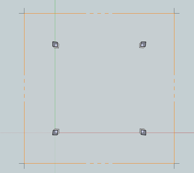
 
Square section legs, no bevels on rail ends. I drew the front face of the rails and used Push/Pull to give them thickness. No bodging and no need for Intersect

4372899093_2077cc05f1.jpg
 
Some subtle angles at the rail/post joint! The rhombus section post would make things neater in appearance i.e.you wouldn't get the toe in - it'd be square on plan.
Hmm 2nd edit I've edited this once already.
A third option is to have one pair of sides flat with simple angles between post and rail, and the other pair toed in with complex angles.
 
err - no...Basic geometry is still the issue I am afraid just as Jacob has described. It's the sawhorse problem.

Here's a section of your approach - ortho view.

792770993_T6Wwa-L.png
 
It's still processing as I post this link. There's no sound and I used a couple of different methods to to make the rails but both amount to simply drawing the face shape and pushing to thickness. The ends fit against the legs with no bevels, no intersect, etc. The legs are not deformed from their square section, either.

Notice that the second rotation in this example is done after the three parts are made. Also note the rotation is parallel to the red axis.

In the shop the ends of all of the rails could be cut cut with a simple 5° mitre. The blade would be left vertical. Assemble the foot board and head board. They'd lay flat on the bench. Then they would be assembled to the side rails as with any other bed.

http://blip.tv/file/3244819
 
Thanks Dave

I ended up doing what you have done with the rails, drawing one face and push/pull earlier today. Problem is there is still the tiny gap I posted earlier.

Is that because I left the rotation as it was and haven't done it the way you stated?
 
Yes, I think that's the reason. In my earlier screen shot examples the leg was rotated 25° and you can see how close to the edge the guideline comes out of the face. At 5°, it would be much closer.

I think this is a good example of doing in SketchUp what you would do in the shop. I would assume you don't plan to but a compound bevel on the ends of the rails. Rather you would cut them with the blade vertical and just put a 5° angle on them. The legs would lay flat on the assembly table while you are joining them to the rail. Then you would stand the foot board and the head board up so they are leaning out at a 5° angle and install the long rails.

I wouldn't draw the legs laying on the ground plane but I would avoid the second rotation until after the foot board/head board is assembled as I did in the video. I think this makes it easier to understand where the axis of rotation should be, too.
 
Dave,
Thanks for helping me get my head on straight! I finally realised that my thinking was being driven by the error of measuring from corners of the tilted bedposts. Intersecting a plane parallel to the floor and dimensioning from the contact points with each side of the posts showed that the distances were equal.

And of course , the section of the leg parallel to the floor is a rhombus but that is irrelevant.
 
I think that if you aim for rhombus section posts (square on plan) your construction will be easier (post and rail faces will be in the same plane with simpler angles at the joints) and the end product will be visually improved - will look square, without the little toe-ins at the corners.
 
Chris, I'm glad that helped.

With the foot end of the leg cut off at the floor, the resulting rhombus has angles of 89.6° and 90.4°. I doubt that most people would be able to see that it isn't square. Certainly no one would notice there's any toe in/out.
 
mr grimsdale":3d3snxk3 said:
I think that if you aim for rhombus section posts (square on plan) your construction will be easier (post and rail faces will be in the same plane with simpler angles at the joints) and the end product will be visually improved - will look square, without the little toe-ins at the corners.
This way way beyond my tiny mind now :D
How would this work in practice Jacob? Posts cut with 2 sides at 5deg off square in one direction?
 
Dave R":ogov86cy said:
Yes, I think that's the reason. In my earlier screen shot examples the leg was rotated 25° and you can see how close to the edge the guideline comes out of the face. At 5°, it would be much closer.

I think this is a good example of doing in SketchUp what you would do in the shop. I would assume you don't plan to but a compound bevel on the ends of the rails. Rather you would cut them with the blade vertical and just put a 5° angle on them. The legs would lay flat on the assembly table while you are joining them to the rail. Then you would stand the foot board and the head board up so they are leaning out at a 5° angle and install the long rails.

I wouldn't draw the legs laying on the ground plane but I would avoid the second rotation until after the foot board/head board is assembled as I did in the video. I think this makes it easier to understand where the axis of rotation should be, too.
Thanks Dave

I still can't understand why it goes out of square because I used the midpoint of the 2 bottom edges as rotation points so my basic understanding says it should still be square. I'm obviously wrong as your example (and my own errored findings show) but I really can't get my head around why.

Surely the axis of rotation is always just off vertical...

I'm getting that headache again ;)

PS Not watched the video yet, just going to make a coffee and will sit down and watch it.
 

Latest posts

Back
Top