This was a drawn-out build, so I’ll go through it in a series of posts.
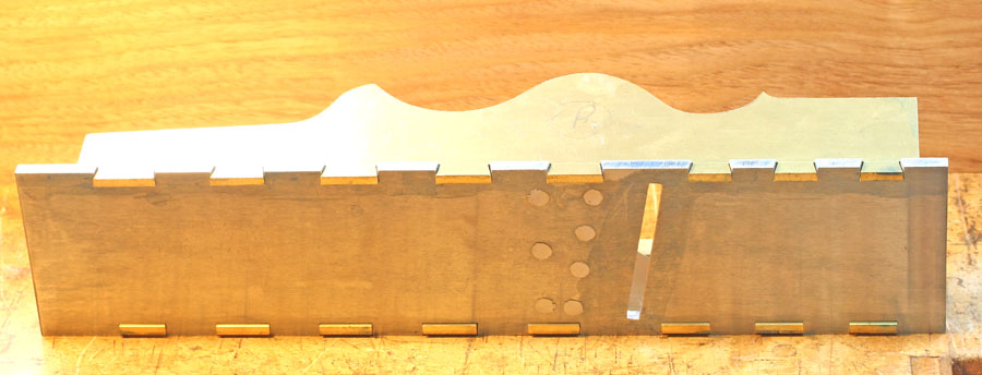
It’s my second panel plane project, the first was an all-steel version made from a kit which had the sides & sole roughed out. Rough is the operative word, and I had some bother getting the sockets cleaned out so the shoulders met neatly without filing away too much metal & making the fit really sloppy. I ended up with visible lines on a couple of the dovetails, as you can see.

However, the body is rock-solid & it turned out a superb user, one of the best-functioning infills I’ve made to date, which begs the obvious question “why on earth make another one?!” I can’t provide a very convincing answer to that, but I did have one valid reason. I’ve been searching for a source of brass that is better for peening than the C385 “machineable” grade which is the only one I can easily obtain locally in plate/bar form. As part of this quest I bought some “H62” brass advertised on ebay The piece is 4mm thick, 300 x 100 mm, which I calculated would be just enough for the two sides for this plane.
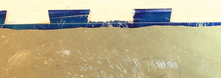
The different nomenclatures for brass used around the world is confusing to us lay folk, but H62 seems to be (roughly) the Chinese equivalent of C108, which British readers may recognise as a good cold-working grade. As soon as I got the piece, I cut a sliver from a waste area and gave it a beating:

The piece on the left is C385, and as you can see, it is in pretty poor shape by the time I spread the end to approximately twice its width. The H62, on the other hand, has been hammered to more than twice its original width with no sign whatever of failure. This looks very promising!
I had originally intended to make a “badger” plane, but decided against badgering it for a few irrelevant reasons. However, I still wanted a skewed blade, & there were a few issues to deal with as a result of that decision. The first issue was getting the side profiles sorted, so I made a couple of wood & cardboard mock-ups from my initial sketches. The first mock-up showed me instantly that I’d badly miscalculated the side-humps & there was nothing for the lever-cap axle to sit in on the left side!

The lever-cap geometry had caused me the most concern when I was at the “inside my head” stage of planning this plane. As a sort of trial run, I’d made a small “pseudo-badger” infill a little while ago. I call it ‘pseudo’ because I skewed the blade 10 degrees, but instead of canting it to bring just the tip through the side, I made it as a “half” rebate plane, i.e., with the blade parallel to the sides & extending out on the right side only.


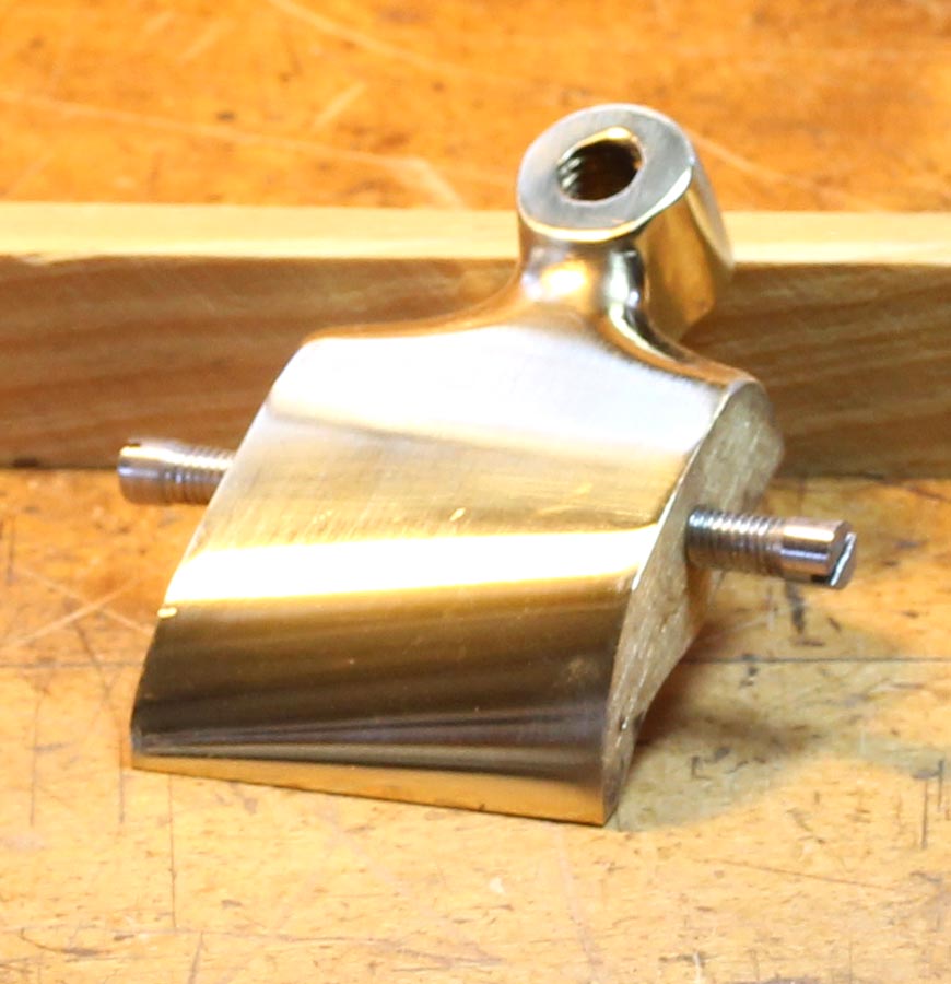
For this plane, I chose to mount the lever-cap square to the body axis. To have the toe contact the cap-iron evenly, the toe had to be both skewed & rotated to the left. It required some careful setting-out, but making the LC wasn’t all that difficult for this narrow plane. I got it close enough that it required only a little adjustment after mounting in the plane to get a good snug fit across the cap-iron.

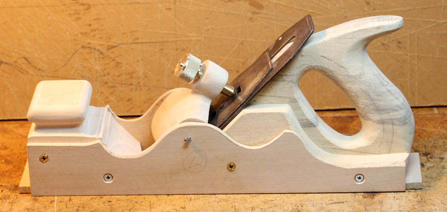
But I could see that it was going to be much more challenging to do this on a larger LC. It would need a very thick block of brass to begin with, and a lot of material would need to be removed on the underside to form the necessary rotation of the toe. On all of the old skewed infills I’ve seen, the LC was mounted parallel with the blade-bed rather than square to the long axis of the plane. This simplifies making the LC itself, the toe still needs to be skewed, but doesn’t need to be rotated. The sides of the LC are angled so they are snug with the plane sides when the LC is sitting on the blade bed. Making the LC is thus more straightforward, BUT, it needs to be mounted so that the toe remains parallel with the bed when the LC is rotated. This requires a skewed axle. It’s hard to explain & difficult to see the relationships precisely in the mind’s eye, but I needed to get my head around it thoroughly, so I made a full-scale wooden mock-up to try & sort it out:

After one failed attempt, I managed to get the correct angles for the LC axle and get a clear picture of how it should be on the real thing. I went to more trouble making the model than needed to just fit the LC, but I also wanted to test the lines & proportion at full scale. It’s no paradigm of model-making, but it gave me the information I was after.
With a little juggling of bumps & dips on my side profiles, I managed to get both sides fitting very cosily within the 300 x 100mm rectangle:

Looks like I’ve got the green light to proceed….
It’s my second panel plane project, the first was an all-steel version made from a kit which had the sides & sole roughed out. Rough is the operative word, and I had some bother getting the sockets cleaned out so the shoulders met neatly without filing away too much metal & making the fit really sloppy. I ended up with visible lines on a couple of the dovetails, as you can see.

However, the body is rock-solid & it turned out a superb user, one of the best-functioning infills I’ve made to date, which begs the obvious question “why on earth make another one?!” I can’t provide a very convincing answer to that, but I did have one valid reason. I’ve been searching for a source of brass that is better for peening than the C385 “machineable” grade which is the only one I can easily obtain locally in plate/bar form. As part of this quest I bought some “H62” brass advertised on ebay The piece is 4mm thick, 300 x 100 mm, which I calculated would be just enough for the two sides for this plane.
The different nomenclatures for brass used around the world is confusing to us lay folk, but H62 seems to be (roughly) the Chinese equivalent of C108, which British readers may recognise as a good cold-working grade. As soon as I got the piece, I cut a sliver from a waste area and gave it a beating:

The piece on the left is C385, and as you can see, it is in pretty poor shape by the time I spread the end to approximately twice its width. The H62, on the other hand, has been hammered to more than twice its original width with no sign whatever of failure. This looks very promising!
I had originally intended to make a “badger” plane, but decided against badgering it for a few irrelevant reasons. However, I still wanted a skewed blade, & there were a few issues to deal with as a result of that decision. The first issue was getting the side profiles sorted, so I made a couple of wood & cardboard mock-ups from my initial sketches. The first mock-up showed me instantly that I’d badly miscalculated the side-humps & there was nothing for the lever-cap axle to sit in on the left side!

The lever-cap geometry had caused me the most concern when I was at the “inside my head” stage of planning this plane. As a sort of trial run, I’d made a small “pseudo-badger” infill a little while ago. I call it ‘pseudo’ because I skewed the blade 10 degrees, but instead of canting it to bring just the tip through the side, I made it as a “half” rebate plane, i.e., with the blade parallel to the sides & extending out on the right side only.


For this plane, I chose to mount the lever-cap square to the body axis. To have the toe contact the cap-iron evenly, the toe had to be both skewed & rotated to the left. It required some careful setting-out, but making the LC wasn’t all that difficult for this narrow plane. I got it close enough that it required only a little adjustment after mounting in the plane to get a good snug fit across the cap-iron.

But I could see that it was going to be much more challenging to do this on a larger LC. It would need a very thick block of brass to begin with, and a lot of material would need to be removed on the underside to form the necessary rotation of the toe. On all of the old skewed infills I’ve seen, the LC was mounted parallel with the blade-bed rather than square to the long axis of the plane. This simplifies making the LC itself, the toe still needs to be skewed, but doesn’t need to be rotated. The sides of the LC are angled so they are snug with the plane sides when the LC is sitting on the blade bed. Making the LC is thus more straightforward, BUT, it needs to be mounted so that the toe remains parallel with the bed when the LC is rotated. This requires a skewed axle. It’s hard to explain & difficult to see the relationships precisely in the mind’s eye, but I needed to get my head around it thoroughly, so I made a full-scale wooden mock-up to try & sort it out:

After one failed attempt, I managed to get the correct angles for the LC axle and get a clear picture of how it should be on the real thing. I went to more trouble making the model than needed to just fit the LC, but I also wanted to test the lines & proportion at full scale. It’s no paradigm of model-making, but it gave me the information I was after.
With a little juggling of bumps & dips on my side profiles, I managed to get both sides fitting very cosily within the 300 x 100mm rectangle:

Looks like I’ve got the green light to proceed….


