


Hi all
Some years ago I took apart a defunct B&Q table saw as it was dead. I kept the NVR switch as I thought it might come in handy one day. Well, that day has come. I'm working on a router table wing to go in my table saw and want to use the NVR switch for a bit of added safety. Unfortunately I didn't know what I was doing when I took the switch out of the table saw and I need help reconnecting it.
I've got the input and output wires but they are not connected in the switch and I'm not sure how to connect a double plug to the output side of the switch to plug my router and vac into as it is 5 strand cable - maybe I can't use it?
Still here goes...
Pic 1 is a general shot of the switch
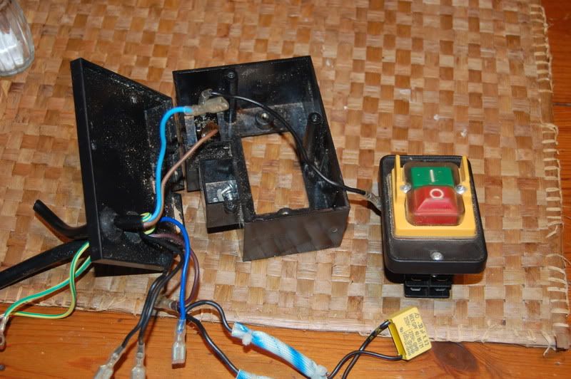
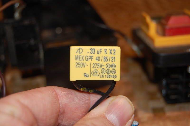
There is reset switch wired in on the input side and a yellow box which I have no clue about as shown in Pic 2
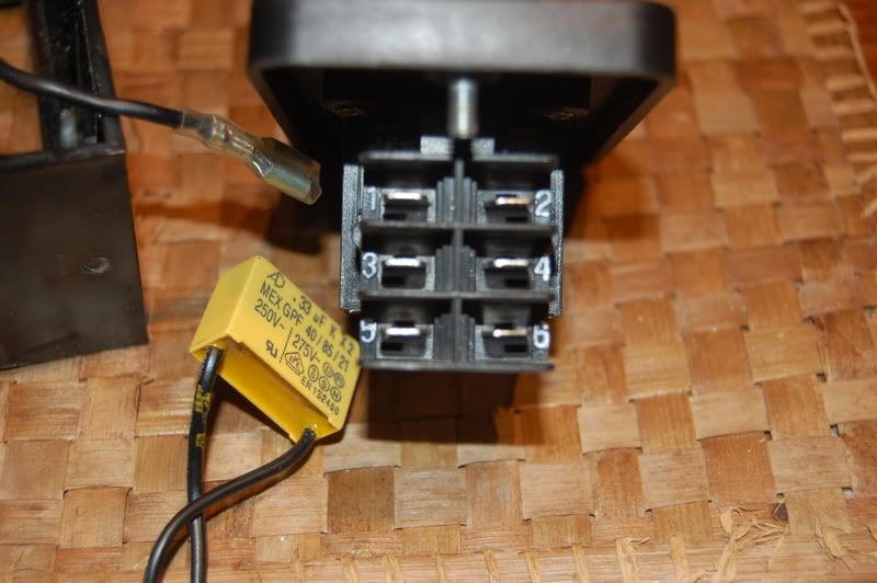
The six ends of cable have to be connected to the switch in Pic 3
There is a wiring diagram on the switch:
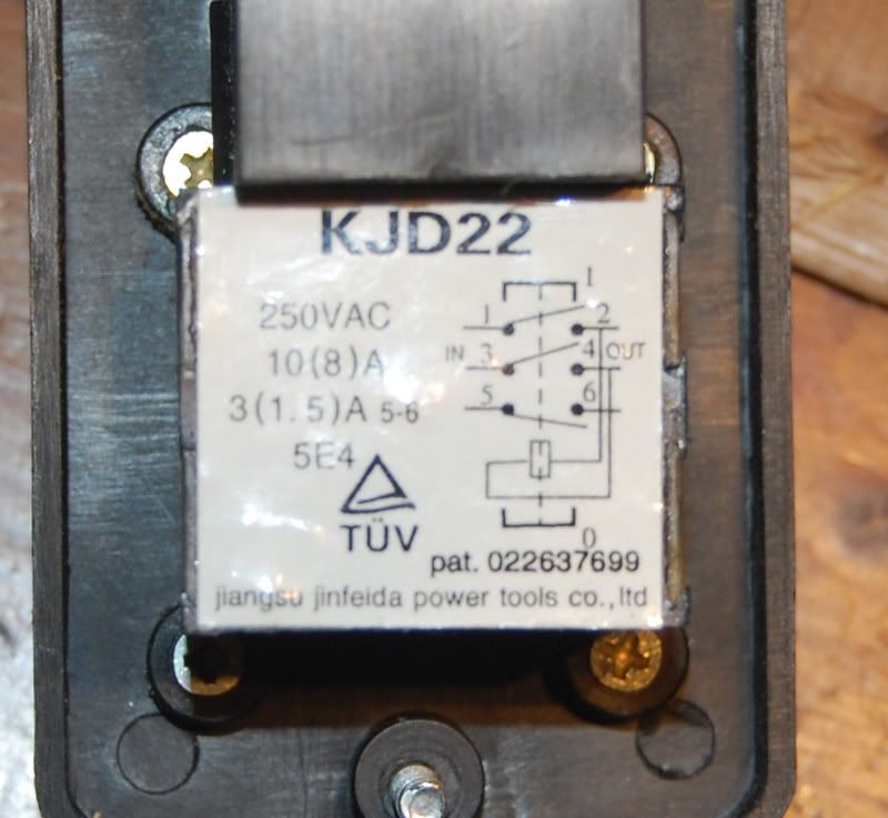
which seems to suggest that the cables from the yellow box are connected to pins 2 and 4 but I have no idea which wire goes on which pin or which wire connects opposite them.
I've drawn a diagram - can anyone help with the connections in the switch and the connections to the double plug?
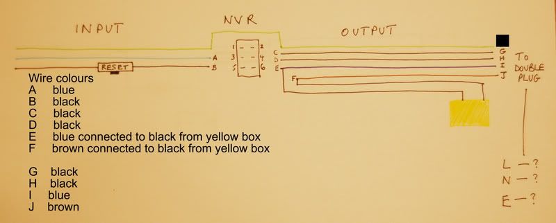
...or tell me if this switch can't be connected to a double plug as it is designed to be connected to a motor!
Some years ago I took apart a defunct B&Q table saw as it was dead. I kept the NVR switch as I thought it might come in handy one day. Well, that day has come. I'm working on a router table wing to go in my table saw and want to use the NVR switch for a bit of added safety. Unfortunately I didn't know what I was doing when I took the switch out of the table saw and I need help reconnecting it.
I've got the input and output wires but they are not connected in the switch and I'm not sure how to connect a double plug to the output side of the switch to plug my router and vac into as it is 5 strand cable - maybe I can't use it?
Still here goes...
Pic 1 is a general shot of the switch
There is reset switch wired in on the input side and a yellow box which I have no clue about as shown in Pic 2
The six ends of cable have to be connected to the switch in Pic 3
There is a wiring diagram on the switch:
which seems to suggest that the cables from the yellow box are connected to pins 2 and 4 but I have no idea which wire goes on which pin or which wire connects opposite them.
I've drawn a diagram - can anyone help with the connections in the switch and the connections to the double plug?
...or tell me if this switch can't be connected to a double plug as it is designed to be connected to a motor!
