The last casting I ever plan to do.......

UKworkshop.co.uk

Help Support UKworkshop.co.uk:

This site may earn a commission from merchant affiliate links, including eBay, Amazon, and others.

gasman

Established Member
Joined
14 Nov 2006
Messages
1,011
Reaction score
337
Location
Near Oxford
I got this years ago from eBay back when I had a constant saved search for 'casting infill plane'. It looks like a block plane, about 7 inches long, didn't come with a blade, doesn't look like it has been use much if at all although the sole and sides are fairly flat. There is a bronze 'bridge' so it is clearly intended for use with a wooden wedge. The 'insides' are all rough cast bronze - so nothing where a front bun or knob might be - and no screw hole to anchor a front knob. The slope of the blade supports is about 18 degrees or so - but it is all quite rough and ready.
IMG_7661 2.JPG

IMG_5759 2.JPG

IMG_6934 3.JPG

So I would like to make a useful block plane out of this and I have several problems therefore to solve.
First, I don't really like wedged planes - I have made Norris-type adjusters for most of my other planes I have made - I prefer this way - plus I have a Veritas adjuster left over and I might just use that as it looks quite good size-wise and I hate wastage.
IMG_4369 2.JPG

Second I need a blade. The width of the mouth aperture is about 43mm - so a 1 5/8" blade from a No 9+1/2 mitre plane would fit. I have an old blade from a Stanley mitre plane which fits and which I have drilled a 1/4" hole in for the veritas adjuster but it is only 2mm thick and would therefore chatter I think. I would like a 3 or 4mm thick blade to fit - I suppose I could make one if necessary? I cannot find much online at first glance which would be suitable
Third, if I am going to get rid of the bridge and fit an adjuster, then I need to make a lever cap, or similar to apply pressure and hold the blade. I think that is a tall order...
Fourth - I think it needs at least a front knob - and maybe even a rear infill to make it look pretty. I have a piece of timber which has amazing figure and has bright orange dust - not sure exactly what it is but it looks lovely... I have rough cut two pieces out as shown in the last photo
IMG_4010 2.JPG

So if anyone has any good ideas for the above questions i would love to hear from you
Many thanks and regards
Mark
 

Attachments

  • IMG_4010 2.JPG
    IMG_4010 2.JPG
    757.7 KB
  • IMG_7661 2.JPG
    IMG_7661 2.JPG
    819.5 KB
  • IMG_5759 2.JPG
    IMG_5759 2.JPG
    742.6 KB
  • IMG_6934 3.JPG
    IMG_6934 3.JPG
    599.4 KB
  • IMG_4369 2.JPG
    IMG_4369 2.JPG
    655.9 KB
Looks like a low angle chariot plane or Irish chariot as Preston called it.

Waiting for the postie to bring me a nice chariot with the wrong iron and I might try this Bill Carter method for reducing the size of an iron.

Bill Carter - How I Adapt Old Laminated Irons Into Small Mitre Plane Irons.

https://www.youtube.com/watch?v=k6Q4TeEeJr0
 
The orange dust is Padauk. A wonderful looking wood when finished in gloss, loses a bit of something with matt or satin finish.
Oh, and that dust can be very bad news to sensitive skins and throats :shock:
 
Thanks Bob - I should have known that but I don't think I have ever used it before
I will go carefully with the dust thanks for the warning
Still not sure what to do about the adjuster / cap iron / blade / infill but I will think about it some more
Regards and thanks
Mark
 
Although you say that it does not seem to have been put to much use, there are some hefty looking hammer blows to the bridge and the flange in the casting, in front of the aperture.

In regard to making a blade, it is worth checking the width of the aperture on the sole, if you haven't already done this. There looks to be quite a taper to the inside faces of the sides, consistent with the casting process. Gauge plate, which is O1 steel, is fairly easily available from a number of sizes, and 40mm is I think, a standard width, and available in a variety of thicknesses, which would leave you with 1 1/2mm gap on each side, if it is the aperture width at 43mm.. There are I think some supplies in imperial, but I am not as familiar with what is available.
Heat treating to harden, I have found reasonably simple with a propane gas torch, but I think both Ollie Sparks and Phil Edwards can do this for you or supply blades. The wrapping paper should tell you if it needs oil quenching, which I think is usual for O1 steel. Jim Kingshott's book on plane making has instructions, but probably info also on-line.

From the photos, it looks as though the bridge is held in place by a couple of pins on each side. May be this would make removal of the bridge piece relatively straightforward, and could provide a position for lever cap pivots, either fitting into the sides of the cap, or pivot points, under which the cap could fit, but be easily removable, much as some of Karl Holtey's planes.

Good luck with this project - I look forward to seeing how it progresses.

Mike
 
Thanks Mike - that is very helpful thank you. I will look again at the weekend and see what is around
I have made blades before - Philly hardened it for me - but I always fancied hardening it myself so that is a great idea
BW Mark
 
Try it Mark, it's fascinating on the primal monkey level of your brain. Blacksmithing was often vaguely connected to magic in history because of the same innate human fascination with fire I reckon.
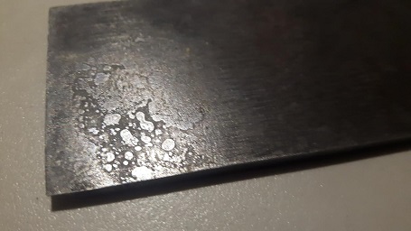
Fire pit of some variety, proper wood charcoal and a hairdryer is another method I've used a few times after being inspired by one of Pete Madex's threads. I have used a gas torch and it will get you there (just) but the pit will far more easily raise the necessary temps. but it is also more involved. After the skill level you've achieved making the actual planes you should at least try if you don't mind me saying. If you oil quench be ready for more fire as it can ignite on occasion. Nothing to worry about if prepared and quite exciting at times. I read various methods of plunging/cooling (I think it's one of those sort of things that inspires different views like Camelia Oil or Genocide), but worth a look at the different methods before you try. I don't pretend to have anywhere near enough experience to offer advice. But it's to prevent scaling like this I believe, although there is doubtless far more to it than that. Only just scratched at the very surface personally.
LB3SgTS.jpg


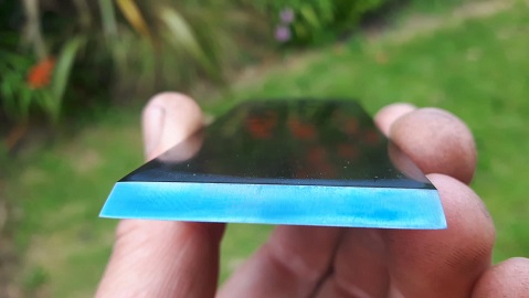
Same Iron after cleaning up and tempering in the oven (while Herself was out!) and a turkey type foil tray filled with sand as a heatsink in the bottom to raise the temps a bit more than standard. Left to cool very slowly.
KfmdqQQ.jpg


The blue rubs off but this is just O1 4mm flat gauge plate and it sharpens as easily and holds an edge just as well as any factory produced O1 Iron I have used. Better than some, actually. But that might be parental pride lol. :D
Go for it Mark!
 
Thanks for the encouragement Chris - will work on it...
I have made slow and sporadic progress over the last few weeks (no change there!)
I started with the pad auk for the infills which were cut roughly to size...
IMG_4010 3.JPG

Then started on the bun for the front and decided to design it on the fly...
Started with a basic chunk and had drawn some ideas on the side
IMG_7918.JPG

IMG_0448.JPG

Then it was just a question of removing the waste a bit at a time using microplanes, rasps, then 80 grit abranet. Once it was the correct shape I went through the grades of abranet until I ended up with this...
IMG_1508.JPG

One coat of TruOil later...
IMG_3677.JPG

Next instalment the rear infill...
 

Attachments

  • IMG_7918.JPG
    IMG_7918.JPG
    617.8 KB
  • IMG_4010 3.JPG
    IMG_4010 3.JPG
    757.7 KB
  • IMG_0448.JPG
    IMG_0448.JPG
    622.9 KB
  • IMG_1508.JPG
    IMG_1508.JPG
    607.4 KB
  • IMG_3677.JPG
    IMG_3677.JPG
    666.2 KB
The rear infill was harder and Im not sure it is there yet but defo progress made
First I had to remove waste to allow the infill to bed down in the rear of the plane
IMG_3044.JPG
IMG_4115.JPG

It took a fair while to get it to sit right as the inside of the bronze casting was so rough and irregular
Then I needed to think about where the adjuster would sit. Too far down the slop and the bronze 'fins' would be in the way. Too far up and the knurled adjuster wheel would foul the rear of the plane.
IMG_3807 2.JPG

I settled on this and carefully drilled a 3/4" hole to the right depth
IMG_2822.JPG

Then needed to drill out the infill so the adjuster fitted once and snug
IMG_7926.JPG

Started shaping the rear infill so the adjuster knob was clear
IMG_7887.JPG

Looking OK at this stage...
IMG_9810.JPG

And the iron sits about right for adjustment
IMG_7926.JPG

IMG_5912.JPG

So the next stage is to think about how Im going to hold the iron in place - whether to make clever cap of sorts and how to go about that
Thanks for looking and comments / criticism most welcome
Regards to all
Mark
 

Attachments

  • IMG_3044.JPG
    IMG_3044.JPG
    753.8 KB
  • IMG_4115.JPG
    IMG_4115.JPG
    628.3 KB
  • IMG_3807 2.JPG
    IMG_3807 2.JPG
    593.6 KB
  • IMG_7926.JPG
    IMG_7926.JPG
    689.4 KB
  • IMG_2822.JPG
    IMG_2822.JPG
    668.7 KB
  • IMG_7887.JPG
    IMG_7887.JPG
    727 KB
  • IMG_9810.JPG
    IMG_9810.JPG
    748.8 KB
  • IMG_5912.JPG
    IMG_5912.JPG
    744.3 KB
  • IMG_7926.JPG
    IMG_7926.JPG
    686.4 KB
I completely forgot that I hadn't mentioned the iron before. So I bought some 5mm gauge plate and cut off 110mm then shaped and ground a bevel and then drilled two 6.25mm holes in it to take the adjuster! Sorry about that
 
A thought or two about how to retain your blade:
Since you're fitting a screw adjuster, methinks a simple wedge would be inappropriate, it would become very tiresome very quickly, having to loosen & re-tighten a wedge each time you wanted to make a small adjustment. My solution to a similar problem in this little chariot plane was to install a thick (~5mm) bridge & use a thumbscrew to tighten a wedge - it can easily be backed off a little while adjustments are made, then twitched up again:
Chariot 2.jpg


The thumbscrew engages a divot in a brass cylinder let into the wood. This is obviously a wedge from another plane, but shows the idea.
Wedge.jpg


I scrape a small concavity in the bottom of the wedge so it will apply maximum pressure at the front & back.

It looks like the bridge on your casting is pretty robust, so something like this might work for you..... ??

Cheers,
Ian
 

Attachments

  • Chariot 2.jpg
    Chariot 2.jpg
    137.6 KB
  • Wedge.jpg
    Wedge.jpg
    88.7 KB
Yep, turned out well.

You obviously got more ambitious as you went along fitting a lever-cap instead of the original bridge, & it looks like you've sweated a steel sole on it to close up the mouth. That part would be worth a bit of explanation, especially how you blended the existing blade bed into the new sole piece.

I've done a few sweated soles, but only on rebate planes where I was able to get files in from the side to re-form the blade bed :) . I started by sweating a slightly oversized piece onto the brass:
a.jpg

Then cut the mouth & filed the bed flush:
e.jpg
This one was also skewed, which added a bit to the difficulty, but by taking it steadily (& with a gracious smile from lady luck!), I managed to get a clean surface and a very fine mouth.

Not sure a skewed shoulder plane is worth the extra effort, but it was a fun project, and it does cut a little more sweetly across end-grain, & I like the way shavings curl out of the escapement instead of balling up inside:
Curly shavings.jpg

I imagine fitting a sole on your plane was a bit trickier and it looks like a single piece, so that implies you used a mill to re-fom the blade bed??

Apologies for the impertinent questions, but as another plane-making tragic I would love to hear any details....
 
Back
Top