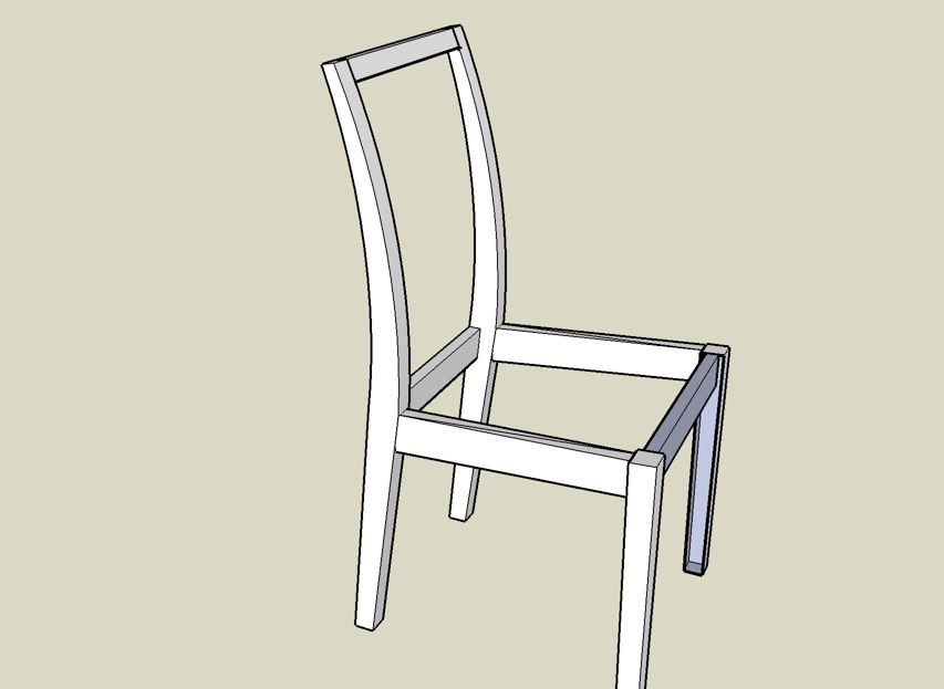
Sketchup Curve question

UKworkshop.co.uk

Help Support UKworkshop.co.uk:

This site may earn a commission from merchant affiliate links, including eBay, Amazon, and others.

noddy67

Established Member
Joined
1 Feb 2006
Messages
253
Reaction score
5
Location
Nr. Tonbridge, Kent
I am in the process of modeling a kitchen chair in sketchup and need to position the rear slats a set distance along the slight curve that makes up the top section of the rear leg. Is there any way to use the measuring tape along a curve or if not any ideas on a alternative method?
Many thanks
 
No, the Tape Measure tool won't work along a curve.

I assume you are working with slats that are somewhat vertical. A method I've used to place slats for the back of a chair is to place the central slat and then construct geometry to locate an axis of rotation for the rest of the slats. The rest of the slats are then placed using the Copy function of the Rotate tool.

For more of an explanation, see this link.

Hope that helps.

Dave
 
Dave, Thanks for your reply. Actually the slats are horizontal as per the following picture. Not sure there is an easy way to specify the distance spacing of the lower slats along the curve or whether it involves backing out the centre of the implied circle and working out the spacing based on the number of degrees etc

KitchenChair1.jpg
 
I see what you're doing.

Since the curve doesn't appear to be circular, the method I previously described wouldn't be useful. You could use a plugin to space the slats.

Here's another link for you to look at.
 
By the way, in the case of your chair, the slats should probably run roughly up a centerline in the side of the chair. You should work out that line to use as a path for the plugin referred to in the link in my previous post.

If you send me your model, I'll make an example.

drkr4109 at gmail dot com
 
Let's see if any of this makes sense. Click on the image for a larger version


Working from left to right.

Your chair drawing.

1. For clarity I copied an upright over to work on it. To find the centerline, I turned on Hidden Geometry and then drew some lines. These lines connect the vertices of the front curve and the back curve. This work is all done outside the upright component.

2. Next, I drew line segments between the midpoints of the lines drawn in the previous step. You have to watch closely to make sure you hit the midpoints. At some places along the back, SU may want to draw a line parallel to either the front of the back edge of it may want to draw a vertical line. Neighter of those would be correct. Zooming in helps to override those tendencies of the inference engine.

I deleted the crossing line segments because they're no longer needed. The path segments are then welded together with the Weld plugin.

I drew a slat for the back rest. This is shown at the top. It was made into a component and then its axis was set so that the origin is at the midpoint of the top, end edge. The origin is the insertion point for the component when the Copy Along Path plugin is run. You'll have to play with the actual alignment of the axes a bit. The correct alignment depends on a number of factors including the direction you draw the original path.

The Copy Along Path plugin was then activated, the spacing (distance between insertion points) was set in the VCB followed by clicking on the path and then the slat component.

3. Each slat component was then rotated to align it. I did this while in X-ray mode so I could see the path line. The center of rotation is the origin of the component axes. I set that point followed by clicking on the center of the bottom end edge below and dragging that point over to the path line.

4. Finally I moved the slats and chair together. If I was drawing this for myself I would just draw the slats in place to begin with.

I hope that all makes some sort of sense.

Dave
 
Dave,
Much appreciated. I think it has stretched my knowledge of sketchup well past where I was expecting to go with this drawing and given that the chair only has three horizontal slats I think I'll follow your advise and just draw them in.

One final question. You probably noticed on the file I sent you that the front rail was shading in grey whereas the rest were all white. I presume this is because I hadn't completed all of the sides correctly in forming the component. I tried erasing and redrawing them but couldn't find which joint was correct. Am I right in this and if so which one did you redraw to get it correct. Is there an easier way than trial and error to spot the culprit in this situation?
Thanks again for your help.
 
I applied a different style to your model which accounts for the tan color and thin lines. The front rail on your chair was inside out. The blue color is the face back color while the white in your model is the outside or front face color. I don't know exactly what you did to get the front rail to be inside out. To be honest I didn't look to see if there was a face missing. I just opened the component and selected all of it by triple clicking and then I chose Reverse Faces from the Context (right click) menu. It's a good idea to stay on top of the face orientations as you work.

By the way, you might find it easier to work accurately if you disable Length Snapping (from the Units dialog under Model Info) and turn off the Profile edges in Styles>Edit>Line Styles.

Drawing the three slats in won't be that difficult--if they are all the same shape, draw one and copy it. You might still find it helpful to draw the centerline to aid in placing the slats. Just delete the line later.

Dave
 

Latest posts

Back
Top