I started fitting the glass scales...
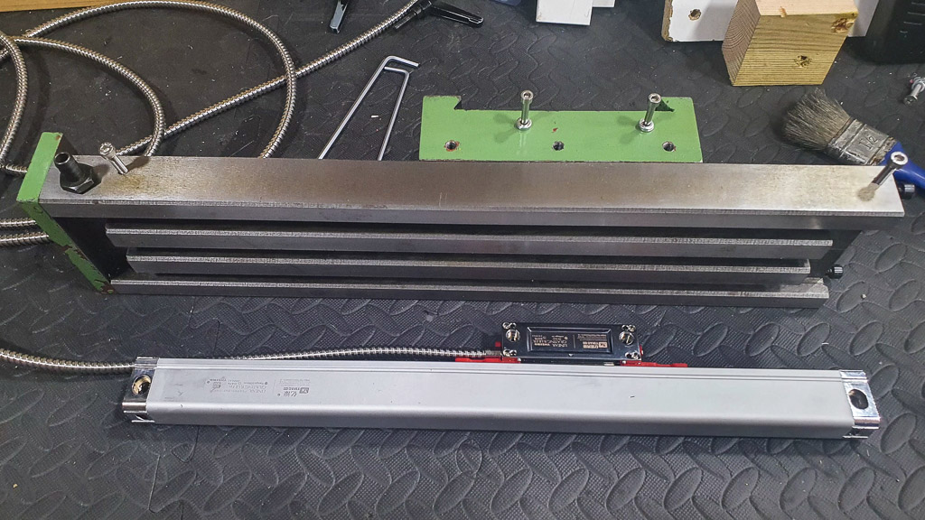
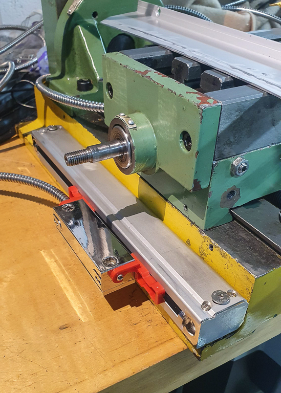
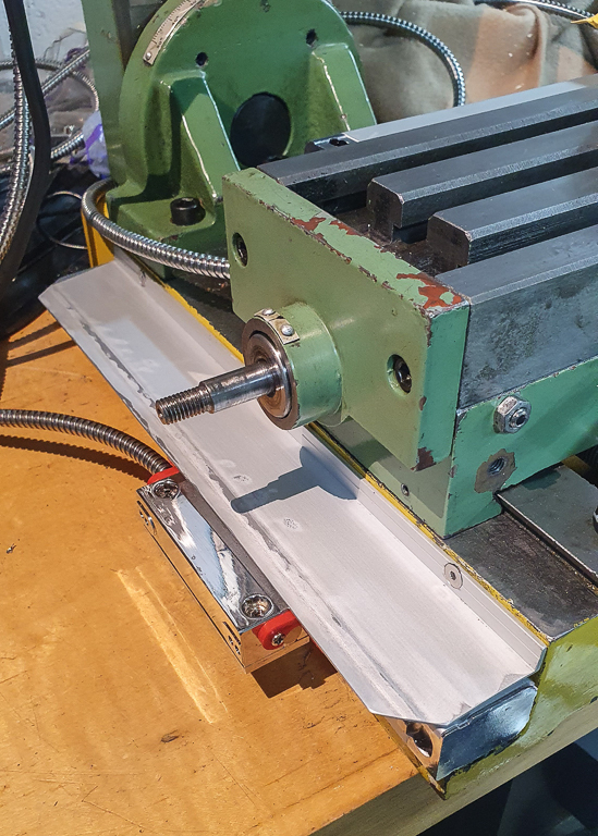
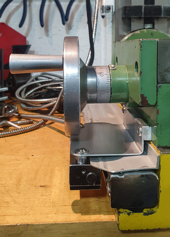
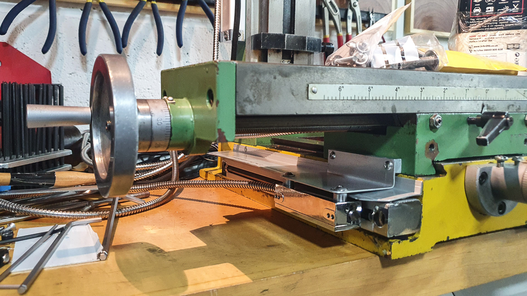
With the X/Y axes carriage removed, it was a simple job of drilling and tapping holes to fit the scale for the X axis. It's offset to the side to avoid the coolant drain port. The image shows the rear of the carriage:
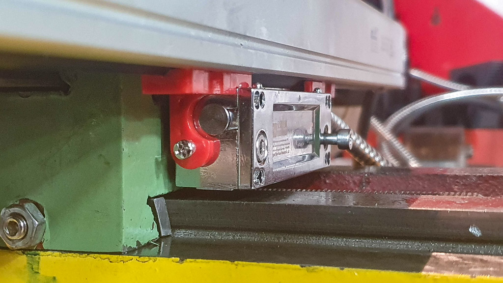
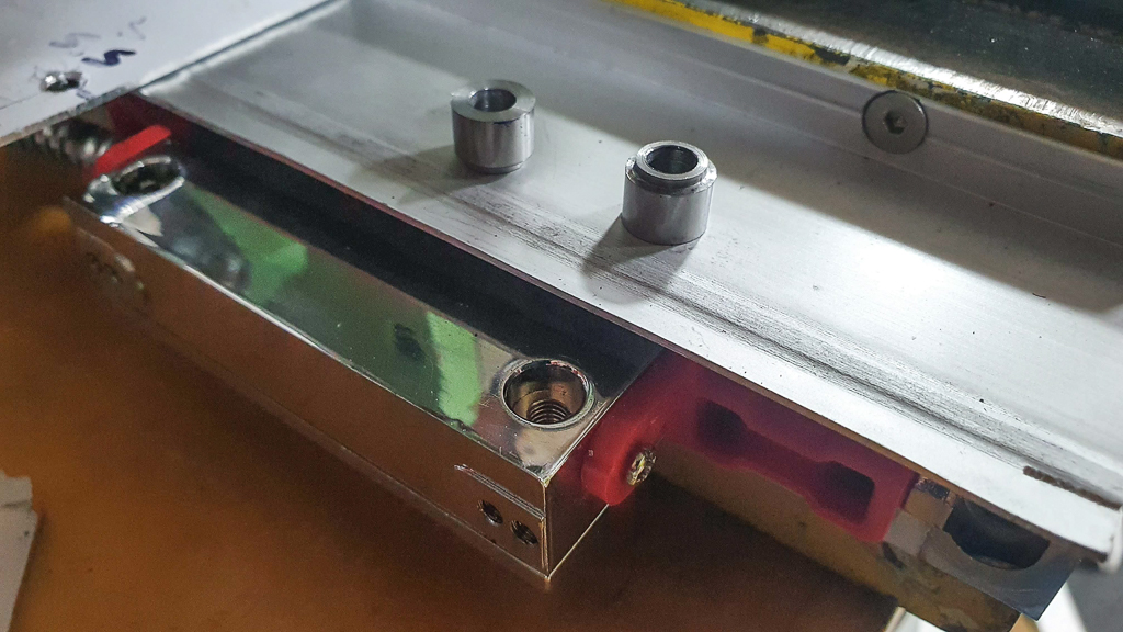
The small red plastic tabs restrict the range of movement but they're present to help ensure the two parts of the scale are aligned correctly...
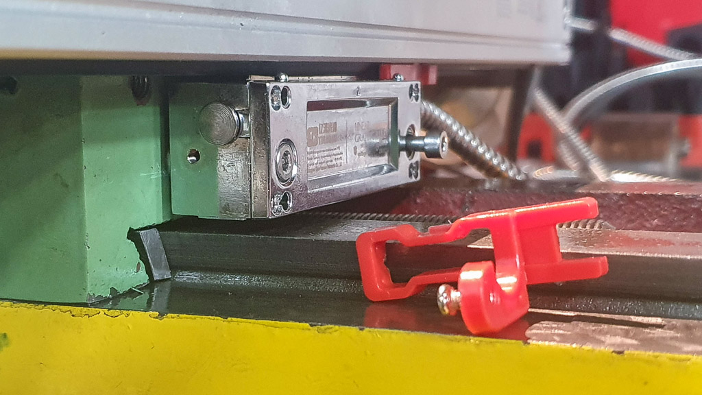
...and they're easy to remove once the hole locations are set:
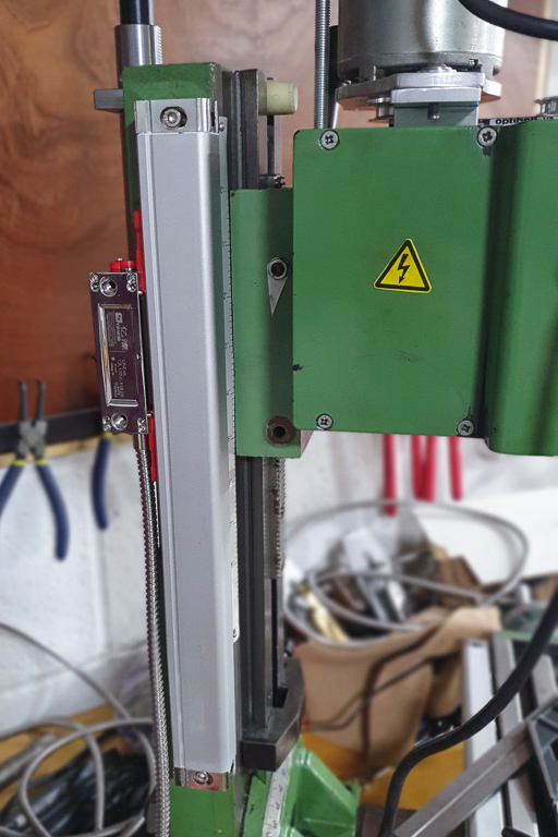
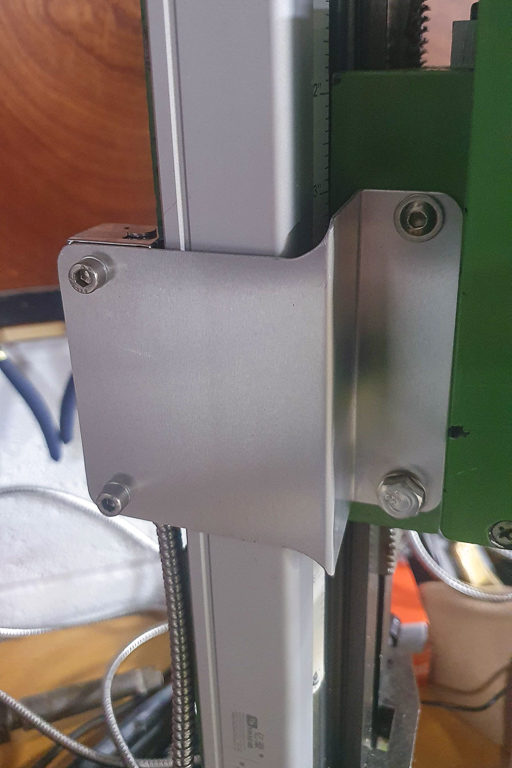
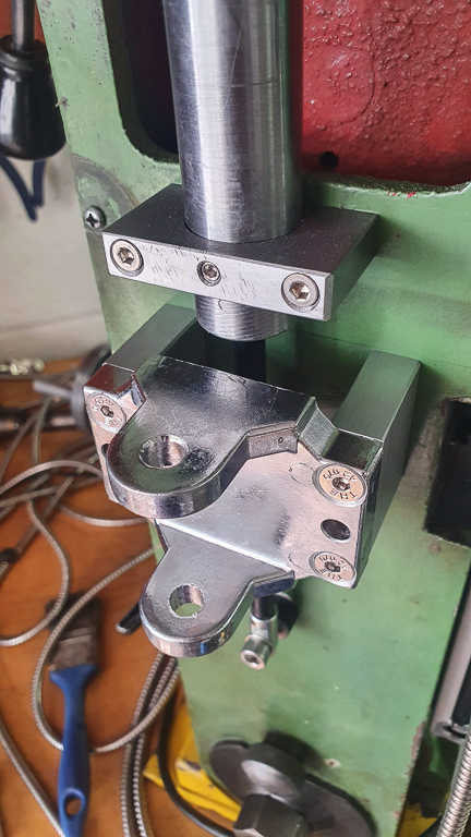
Next it was on to the Z axis. It would have been less work to position the slider of the scale facing to the front, but then the slot in the main body of the slide would be exposed to chips. The left side of the head has an M8 tapped hole that was for the old spring based lifting mechanism (replaced with the gas strut), and an M6 tapped hole would also become available once the (now useless) arrow indicator was removed:
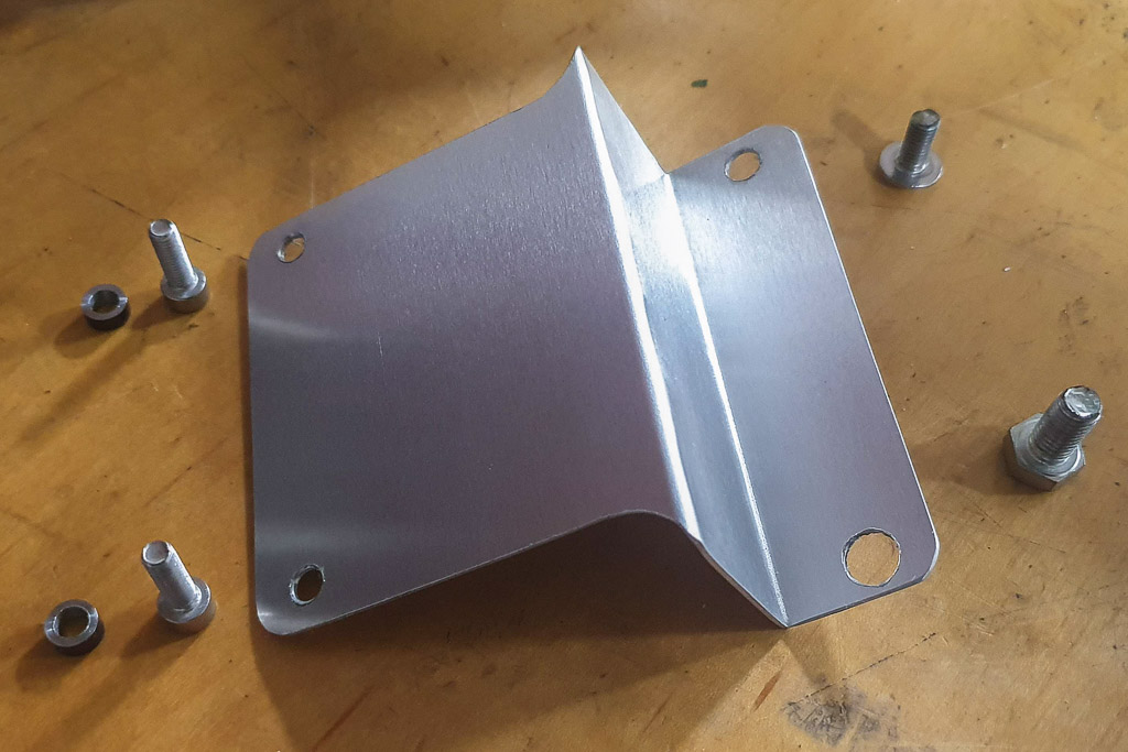
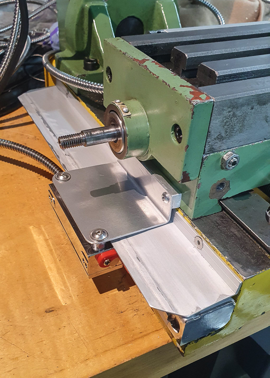
A bit of bodging with some aluminium plate went surprisingly well (other than being very soft and "gummy" to drill), and I needed a couple of spacers (basically thick washers), which were turned on the mini lathe. Then I dropped one. Which of course instantly entered another dimension and could not be found. So I had to machine another

:
Bit of a random assortment of screw heads, but it's what I had in the right sizes:
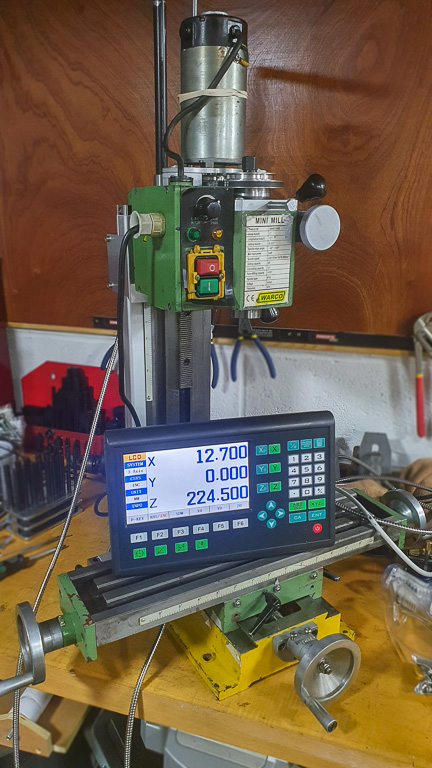
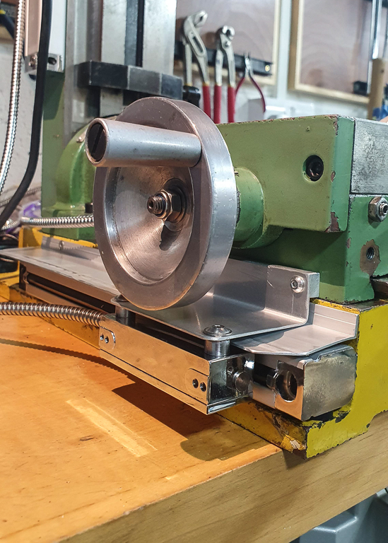
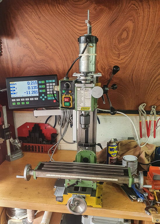
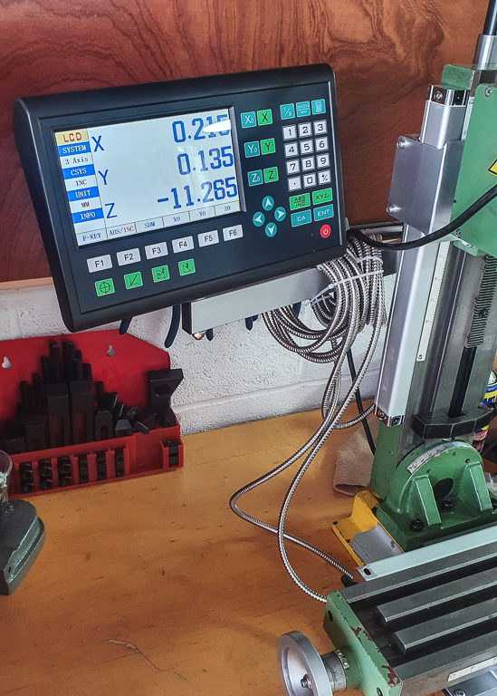
X and Z scales working well; though I've not made any attempts to indicate them in yet:
The Y scale will require a bit of thinking. It would be easy with it the "wrong" way up; but that would definitely get the slider full of chips. I'll have to make another aluminum bracket, but I need to work out how to mount it without fouling the holes to bolt the machine to a worktop or restrict X axis movement.
The sliders do come with aluminium cover plates BTW, but there's not enough space for them on the mini lathe (plus it wouldn't work on the Z axis with the aluminium bracket passing over the top).


