oak beam structural advice

UKworkshop.co.uk

Help Support UKworkshop.co.uk:

This site may earn a commission from merchant affiliate links, including eBay, Amazon, and others.

RogerS

Established Member
Joined
20 Feb 2004
Messages
17,921
Reaction score
276
Location
In the eternally wet North
I'm in the process of renovating our en-suite. Last done in 1995 and the stone bath bought in a sale has sat in what was our dining room for the last three years (so LOML tells me). However I am in a bit of a quandary.

When our builder removed a staircase and made good the ceiling way back in 1990, he was a bit of a bodger and at the time I didn't know any better either. So he simply nailed bits of old oak, that had come out from other parts of the building, as supports to the sides of the beams on either side of where the staircase went. He then laid some odd oak beams between these supports and plasterboarded over the gap. He knew that we were fitting a corner bath (as it was all the rage then) and so did plan ahead and put a supplementary vertical supporting beam to give additional strength to the beam that spanned the width of the kitchen. So far so good. The oak beam supports do look a bit naff now TBH and I'd never let him get away with it were he around today.

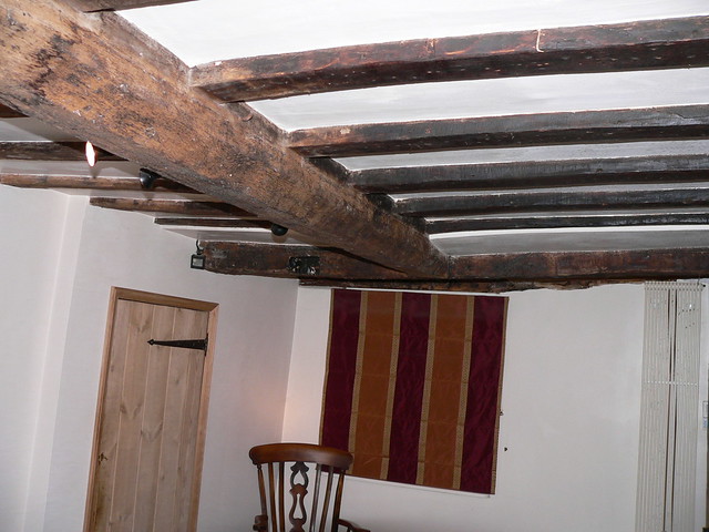
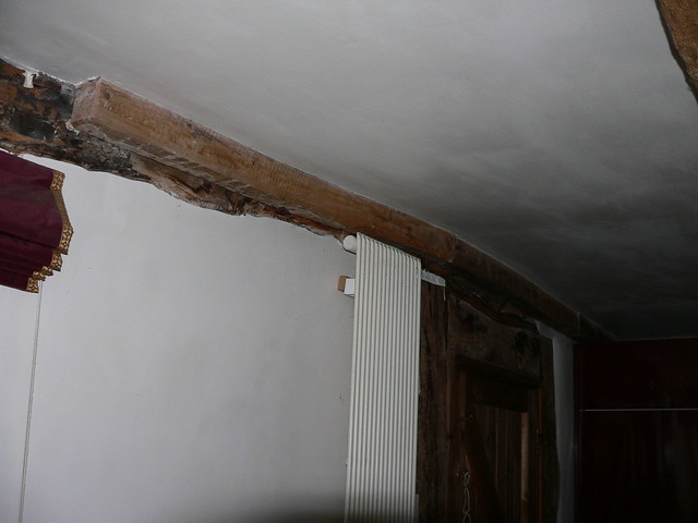
These are the supports on the outside wall


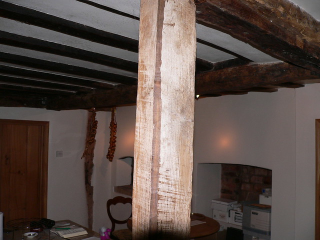
and these are on the side of the beam spanning the kitchen and the vertical extra supporting beam in the background


Notice the small arrow pointing at an empty mortice. I'll come back to that.

From the top we see this


Remember that empty mortice ?
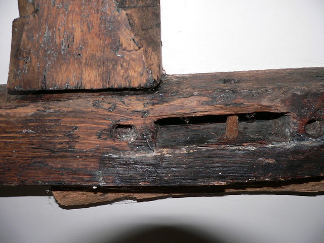


Well, it's roughly beneath this empty mortice


and you can also see the half-wedge tenon on the end of the cross beam (in the picture above) that ties into the main spanning beam

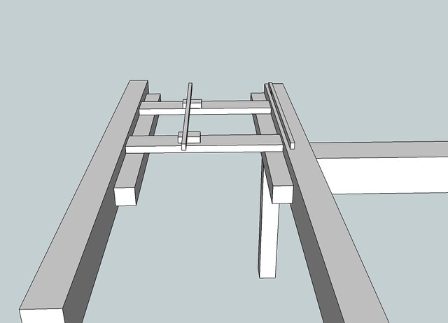
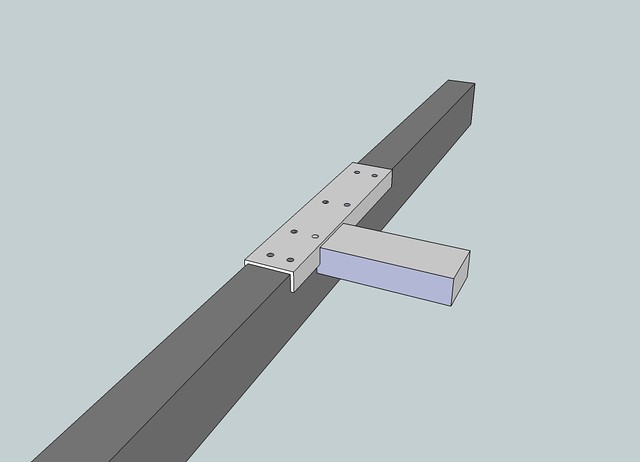
and if I draw this out in SketchUp it looks like this


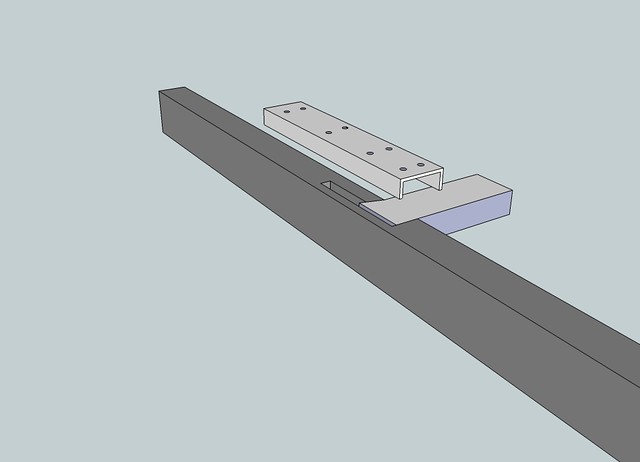
and in x-ray
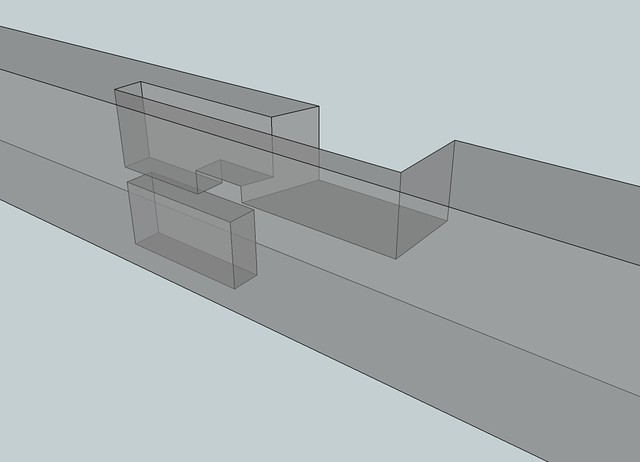


and although that beam is pretty chunky at 135mm wide x 210mm deep, there ain't a lot of meat left around that joint. Let's face it, my builder probably put the vertical support in the wrong place but it can't be moved as there are tiles around it. And sticking in another vertical supporting beam is going to look a bit naff.

Now my quandary. The new bath going in weighs 68kg. Filled to the brim, 368kg. It's base is roughly here although more oval than round.
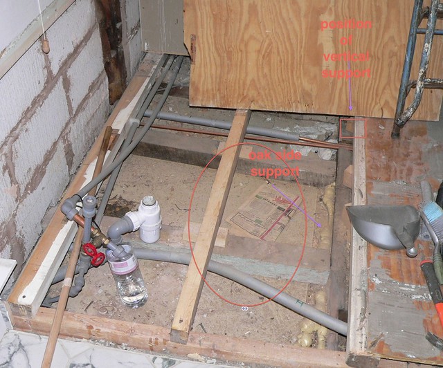


and I am wondering if that spanning beam is going to be strong enough around that joint. There is some extra support from that side support but is that enough? Is it actually needed or is that spanning beam joint good enough?

If it needs strengthening I see a few options.

1) Easiest is to fit a very tight fitting stub of a tenon into that top mortice slot as the sides should resist inward pressure if the bath tried to deflect the beam downwards (I think that is right). And fit one into the bottom mortice but pegged ...as this will be under tension if the bath deflects the beam downwards.

2) Least favourite is to remove the ceiling and replace that inner supporting piece with something a bit meatier running the whole height of the spanning beam...coachbolted into the spanning beam with counterbored holes filled with mock oak pegs. Then fiddle about forever and a day with stain trying to match the new oak with the old. And make good the ceiling.

What does the team think?

TIA
 
I take it from the last photo that the bath is going to be sat on a raised section of floor?

I would replace those longitudinal lengths of softwood, 3x2 and 2x2 by the looks of it, with 5x2 on side to spread any pressure. I'd lay across the top of the 'side support' beams the full width of the room (running the opposite way to your existing softwood beams) then add a few noggins to prevent twist. I'd also fill the mortice slots in with some oak and glue/peg into place.

If I'm looking the photo wrong and this isn't the case, you could bolt angle irons to either side of the joist within the ceiling void after filling the mortice slots.
 
If those joists are only supported by the bits of oak nailed to the sides of the beams than the load bearing is only as good as the nails. Drill and counterbore and fit some studding & nuts and plug the ends.

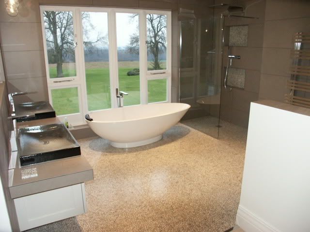
Your bath is never going to be brimmed and even with somebody in it I doubt you will get near your 368kg. And if its anything like the similar bath I fitted about the time you also bought the same one then its won't get used more that 2 or 3 times a year. I hope you and your good lady are not too short as the problem is anyone under 6ft slides to the middle, you can't even sit up and read in teh bath (so I'm told) but it looks good.

PICT0225.jpg
 
MMUK...I like the idea of angle iron although the ceiling void isn't that deep. Also like the idea of changing the direction of the bearers...although actual size isn't important as they bear directly onto the oak cross beams. Getting the waste away is going to be a challenge hence the raised platform for the last bath.

Jason..yes, that is indeed the bath. Only our bathroom is tiny compared to the luxury one in your photo. Take your point re the nails holding the side support beams. This diagram might make things clearer.


So you reckon I am worrying unnecessarily as to the strength of the oak beam around that joint?
 
hi what about flat plates fitted each side of beam bolted through beam along the damage or least a bit longer than damage 3/8 steel painted black would look authentic
pip
 
Nice idea, pip. I can only get one in because of the other beam (the one with the wedge) coming at right angles. I was wondering about slotting a metal plate inside the beam.

Looking at this photo you can see that there is some sag in that beam BUT and a BIG BUT I think that that has been there over the last hundred years or so because the floor above (part of the bathroom) was tiled back in 1995 and there is not a hint of any cracking in the tiles or grouting. I really really don't know what to do.


That beam that comes in at right angles is very ling and very heavy plus whatever is above it loading it


but then I get to thinking that it's not moved since 1995 and that the load of the bath is shared with the outside wall beam.
 
FWIW, I personally would, if avoiding making good downstairs, lay another set of joists on top at 90* to spread any load and fill the tenons/mortices. It would possibly mean having a step up into the bathroom and a short door but that wouldn't be at all out of keeping with the property I don't think.
 
You're right there...steps up and down all over the place. And the bathroom already has a stepped area where the bath is going/where the old bath was. It's just that 'weak' (if indeed it is) section of the beam that is mithering me. I don't have any problem with laying more joists but at the end of the day, one end of them is still being supported by that beam.

The other beam coming in at right angles is quite long....this is the other end.


Its getting past my bedtime and will look again in the morning. However, is it possible to either steel plate from beneath or bolt through from beneath with a plate on top? I may be way off beam (oops) but will look again at it. The bolting vertically is a boat building method which may work. If this a possble option then a bit more installing detail can be worked out. Not to be beaten and you shold not worry too much...but you probably are. In my experience there is usually/always an answer but you haven't found it yet. Best wishes.
 
For clarification ,there is plenty of support at the wall side of the floor (that's lh in the 3rd photo). It's that 'floating' joint where the two beams join that is my concern. I am wondering if I'm worrying about nowt as the floor above this area has been tiled and there are zero cracks in either tile or grouting and they've been down for 20 odd years. Mind you, we rarely used the corner bath preferring the shower so maybe I am trying to convince myself.........going round in circles.
 
I think I may have arrived at a solution. Get my local blacksmith to fabricate a steel saddle that will straddle the joint and be bolted through to the beam underneath. I reckon it should work.


Thanks to everyone for the suggestions which triggered off this solution
 
jasonB":3qjx0u3o said:
Might be cheaper to just use a small structural channel, this e-bay seller is quite good for short lengths

http://stores.ebay.co.uk/B-E-J-Engineer ... 34.c0.m322

True...if I can get the right width. :idea: :idea: Actually if there is room I could use one of those channels but upside down. :idea:

or even use it the right way as planned but angle grind off the flange on one side as it doesn't do much since it has to be cut anyway to clear the other beam.
 
Hi Rogers. Sorry been out all day. Your plate is more or less what I was thinking. I was going to suggest bolting through from beneath with big bolts...you could make them from studding and a large square washer on the underside...you don’t want to crank up the bolts and pull them through..probably not with Oak. I would prefer seeing the bolts right through so they are not relying on a large screws on top ie bolts in shear rather than screws in pull out ....but they may be fine and you are doing all your work on top side. The down turned edges is a good one and will give additional strength but with a sag in the beam or even just the rough surface, you will need to do a bit of packing, but that could be done first. A bit of thought needed her to have the perfect most foolproof solution. The beam sags but the plate is flat/level. I had thought the plate to the cross beam would be welded as a tee-plate. I think you are almost there. Just need to decide sizes of steel and bolts. You may need to carry the plates a fair distance along to create the saddle effect. ...more than your sketch I would have thought. Remember you are bolting up to existing camber/sag on the beam and not to pull them straight. A fine touch here. Restoration guys use resin cast into pockets and I have seen them do it to the rotten ends of beams over old school halls say 225 x 225, done with several dowel bars drilled into the good cut ends and a temporary box shutter created to pour in resin along a perhaps 450 length. Seems to work well so if you were anxious you could use resin in the old mortises after giving them a good scrape-out to clean wood. The use of channel is a good strong one ..terrific strength in a channel laid face down so a definit possibility. You may still want a blacksmith to bore or punch the holes. An alternative was straps rather like U shaped saddles ..as you see on old beam trusses and bolted through up onto the to edges. It would be traditional looking at least when it would have been visible. Is it coach screws that you envisage you will use....big and long? One last thing...beams were often reused from other buildings and built in with sags and twists etc. Best wishes.
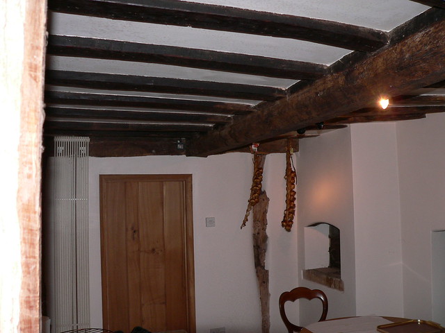
 
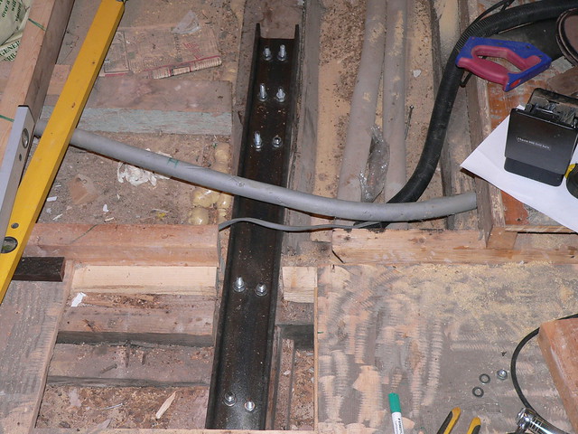
Just to close this off, the channel is finally in place. Like all good projects it did not go quite according to plan. I had some lengths of 10mm studding that I'd bought when I thought I would be making my own bench. A quick Google for tensile strength and a quick double-check with 9fingers (glad I did) showed 10m would be fine. Holes in the channel drilled OK although I hate getting swarf in amongst the woodwork. You can clear it up as much as possible but Sod's Law says that you will miss a bit - only to find it embedded in the finished face of a cabinet.

First pilot hole through the oak went straight through a place where counterboring for a 10mm nut wouldn't be sensible. So tried hole no.2 which was fine. Ran a holding bolt through and drilled out the rest. Mistake 2...should have put some more holding bolts in to keep the channel still while I drilled...some 10mm holes a tad out of alignment. Counterboring for the nuts on the underside of the beam was a nightmare. Getting the holes concentric was tricky. My Irwin was a touch undersized and so the only option left was a Forstner bit. But trying to get it concentric with the 10mm hole a tad tricky and not that successful. In retrospect I should have drilled a suitable hole vertically in a scrap of wood and screwed it to the underside of the beam in position - hole by hole. But 12 holes to drill and I'm lazy so I didn't bother. Most turned out OK doing it freehand.

Got the studding only to discover that my memory had failed me and it was 12mm. Decision...drive down town and buy some 10mm studding or enlarge the holes in the metalwork, in the beam and then get an even larger Forstner to take the 12mm nuts....forget any washers, those nuts ain't pulling through 200 year old oak. Earlier 9fingers had suggested 12mm to be on the safe side anyway (just call me Isambard Kingdom ...the king of over-engineering) so that is the route I took. In hindsight it would have been quicker and easier to have driven down town as I had to chisel out counterbores for the larger nuts. How Michelangelo painted the Sistine Chapel I'll never know.

Discovered that even 12mm long drill bits (that beam is 10" deep) will whip very nicely thus guaranteeing that the holes will not be vertical. So lots of farting around tweaking holes so everything would line up. Took best part of a day.

Anyway, here it is

 
Well done, virtual pint for you!
It's so good when a plan, replan and re replan finally come good. SWMBO's just don't get the concept that refurb work is not the same as new build.
 
hanser":3phvxwe4 said:
.... SWMBO's just don't get the concept that refurb work is not the same as new build.

You are so right. I said to her 'Would you like me to run through what is going on?' to be met with a blank stare. Mind you, I ain't half clocking up the brownie points as at last I am doing something on the house.
 
How about Bat Straps ?

These twisted holding down straps secure and restrain structural floor and roof timbers to walls in situations where the two are perpendicular to each other.

The galvanised straps have multiple fixing holes. They should secured to timber with 50mm No.12 wood-screws and plugged and screwed to masonry.


Heavy duty galvanised steel, with 90° twist 150mm from end.

Galvanised straps are manufactured from hot dipped galvanised steel to BS EN 10346 :2009 + G275.

Designed in accordance with The Building Regulations, BS5268 Part 3 and other building standards for vertical and horizontal restraint.

Multi holed at 25mm offset centres, restraint straps should be fixed using either 50mm long no. 12 woodscrews (using wall plugs in masonry for vertical restraint) or 75mm x 4.0mm diameter galvanised nails into timber
The twisted holding down straps are manufactured from 5mm x 30mm and are available in 1 metre and 1.2 metre lengths. Bat straps are available in packs of 10
 
Back
Top