How do I accurately transfer CAD drawing to sheet of wood?

UKworkshop.co.uk

Help Support UKworkshop.co.uk:

This site may earn a commission from merchant affiliate links, including eBay, Amazon, and others.
haggis999":1q8hzvel said:
Jacob":1q8hzvel said:
Not sure what the OPs problem is. Maybe it's down to trying to use Autocad for working up an extremely simple design?
Pencil, straight edge, full size rod, a lot easier.
PS a router is not a good tool for cutting up plywood. The design itself, using Autocad, cutting with a router; obviously making a very simple job much too complicated!
There was far more to designing the exact shape of these shelves than is obvious from the end result I have presented here. AutoCAD LT proved to be an excellent tool for my purposes, especially as I already had this software and knew how to use it.

You've told me that a router is not a good tool for cutting plywood, but you omitted to tell me what would be better! I've already made it clear that I'm not an experienced woodworker, so feel free to point me in the right direction.
Depends what kit you've got but personally I'd re-design it so it could all be cut on a table saw. Or a band saw followed by hand plane if desperate. But router - only for those cut-ins and only if they are absolutely essential and can't be designed out - which I'm sure they can. (Whats a word for "cut-ins" concavities etc?)
Design is as much about how you are going to make the thing as its desired function and appearance.
 
Mattias Wandell at woodgears.ca has a utility called Big Print.

It overlays a grid onto larger drawings so that the big image can be printed on A4 and then joined up using the grid outline with either tape or glue. I have forgotten what the import file types are but will probably include pdf.

I have used it and it works well and accurately
 
has to be said - but as a rule print outs are not regarded as accurate unless with specialised machines onto stable media. Even worse if you are taping sheets together!
But its more likely that you want precision rather than accuracy - i.e. pieces which fit together well even if out overall by a few mm. A hand drawn template might be good enough.
 
Jacobs right in that printers available to the domestic user are generally likely to be slightly out. The obvious test is to printout 2 or more lines 6 inches long and at right angles and then to measure with a ruler. The difference if any will tell you how far out the printer is. You can then adjust the printout to be close to exact size.

My own experience has been that my laser printer has only even been less than 0.5mm out and that printing at 101% of size cured the issue.
 
Jacob":2sn42ibo said:
Depends what kit you've got but personally I'd re-design it so it could all be cut on a table saw. Or a band saw followed by hand plane if desperate. But router - only for those cut-ins and only if they are absolutely essential and can't be designed out - which I'm sure they can. (Whats a word for "cut-ins" concavities etc?)
Design is as much about how you are going to make the thing as its desired function and appearance.
I have a hand-held portable circular saw, which made a much better job of my rough cut than my first attempts with a jigsaw, though the jigsaw may just have had the wrong blade to avoid splintering on one side. I also inherited what I think you would call a table saw from my father-in-law, who was an expert woodworker, though it's been sitting unused in my garage for 5 years.

However, there are good reasons for the 'cut-ins' in my design. One is to avoid interfering with books on adjacent shelving. Another is more cosmetic; I have deliberately made four edges run parallel with all four sides of the equipment placed on top, thus avoiding the appearance of kit that has been placed on a shelf at a random angle.
 
I've come late to this thread so you may already have decided on the way ahead, so I hope I'm not repeating what other forum members have said, but this would be my view, for what it's worth:

Why not just crop the drawing into A2 sized segments - four say, and save each segment as for example 'Top LH, Top RH, Bottom LH bottom RH', then line up all four segments (or however many you need to be able to print the whole design on A2 sized pieces), and tape them onto the board? I've saved your drawing then in Photoshop have cropped the drawing into four overlapping segments to allow for taping the sheets together, and saved each segment as 'AV Shelf top LH', AV Shelf top RH' etc. To show what I mean, I've put the four segments onto one sheet using MS 'Paint'. If four segments wasn't enough to fit onto A2, just crop the drawing into however many segments you need, then print off the A2 sheets and tape together.

Hope that helps a bit.

Good luck with the project!

David.
 

Attachments

  • AV-Shelf in four segments.jpg
    AV-Shelf in four segments.jpg
    67.5 KB
As I mentioned in earlier posts, I was never happy with the idea of taping several A2 sheets together, as I viewed it as being the potential source of more problems. After reviewing my options, I decided to get a local print company to produce a full size A0 copy of my drawing, which turned out to be very slightly larger than full size. However, all the right angles were still right angles, so I reckoned that the drawing still retained the same proportions. The increase was just over 0.17%, which increased the longest diagonal by only 1.35mm.

That was close enough for my needs, so I have made a start on marking out the outline on my first shelf by making pin holes through the drawing. After drawing lines to join the dots, I will run various measurements to confirm that all is well. As my dad used to say, measure twice, cut once.
 
haggis999":frpxnr02 said:
As I mentioned in earlier posts, I was never happy with the idea of taping several A2 sheets together, as I viewed it as being the potential source of more problems. After reviewing my options, I decided to get a local print company to produce a full size A0 copy of my drawing, which turned out to be very slightly larger than full size. However, all the right angles were still right angles, so I reckoned that the drawing still retained the same proportions. The increase was just over 0.17%, which increased the longest diagonal by only 1.35mm.

That was close enough for my needs, so I have made a start on marking out the outline on my first shelf by making pin holes through the drawing. After drawing lines to join the dots, I will run various measurements to confirm that all is well. As my dad used to say, measure twice, cut once.
Why not just draw it with a pencil, ruler, compasses and straight edge?
Do you have a pencil sharpening problem or something? :lol:
I don't see what your problem is, the whole thing looks incredibly simple and basic and should be the work of a few minutes.
I think you will have a problem cutting it out - but I'd blame the design for that.

PS drawing board, T square, set square, pencil, sharpener, rubber, are all absolute essentials for any would-be woodworker trying to design anything.
Or next best, for a design like this one - improvise with a large enough piece of ply

PPS revisiting your first post.
Drawing the lines sequentially and hoping they will join up is a non starter. Even on a small scale this wouldn't work.
It definitely sounds like you need some drawing practice and would be much better off without Autocad. You can't put pencil lines on a piece of wood with Autocad - it's the wrong tool for the job. Maybe some geometry revision too!
I'd use a drawing board (as above) and an A0 piece of paper (or a piece of ply for a template) start by drawing the 485x555 rectangle set at 30º, as per your drawing. Then add the triangular bits.

PPPS it's not clear from your drawing what the component is supposed to be doing, e.g. is it vertical of horizontal? If we knew, I strongly suspect a better design would be possible.

So it's back to the drawing board!!
 
Hi Jacob,
You appear to be focusing on the design of my shelf, which was never the subject of my original post. As previously indicated, there was far more information on my CAD drawing than is relevant to describe here. That other information was key to finalising my design. Drawing boards have all but disappeared from the modern world, and given my IT background, using CAD software was an obvious choice. How to 'put pencil lines on a piece of wood' is the real subject under discussion, and I really don't see how it makes any difference whether the design originates from CAD software or a drawing board.

It's a pity that you didn't make your suggestion to draw a 485 x 555 rectangle set at 30º much earlier in this thread, as it sounds like a much better method than my original attempt to draw all the lines sequentially. It also has the advantage of only requiring me to measure one non-square angle instead of two. As it is, I have now completed marking up my plywood by pricking through from my full size paper drawing.

I suspect that you might be getting a bit old and forgetful, just like me, as you appear to forgotten my frequent references to this being a shelf. I doubt if you would really recommend a vertical shelf...

David
 
Haggis999

Their is an ignore function where you no longer see some peoples posts, it works well.

Profile/friends & foes

Pete
 
haggis999":3tcdo2mv said:
.... I really don't see how it makes any difference whether the design originates from CAD software or a drawing board.
The CAD doesn't seem to have solved any problem, if anything quite the opposite. You end up having to use a pencil - might as well start with one.
It's a pity that you didn't make your suggestion to draw a 485 x 555 rectangle set at 30º much earlier in this thread, as it sounds like a much better method than my original attempt to draw all the lines sequentially. It also has the advantage of only requiring me to measure one non-square angle instead of two. As it is, I have now completed marking up my plywood by pricking through from my full size paper drawing.
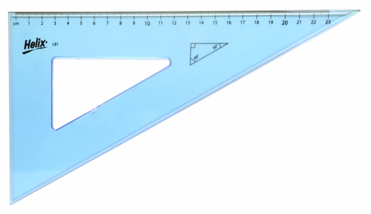
Very basic drawing skills involved here, as you are learning! Better late than never - get back to basics and ignore the computer. NB you don't even need an adjustable set square for your very simple drawing - a basic 30/60º square does it all
I suspect that you might be getting a bit old and forgetful, just like me, as you appear to forgotten my frequent references to this being a shelf. I doubt if you would really recommend a vertical shelf...

David
Could have been the vertical side of a tilted shelf for all I knew. It still looks over complicated as though it's a solution to something which isn't really a problem

521c43c9326de-zoom.jpg
 
There you go Haggis999, your computer is rubbish, your drawing skills are rubbish, your shelf design is rubbish.

Doesn't that foe button look tempting...

Pete
 
Pete Maddex":3ucqdztf said:
There you go Haggis999, your computer is rubbish, your drawing skills are rubbish, your shelf design is rubbish.

Doesn't that foe button look tempting...

Pete
Nah, I'm a laid back kind of person. Jacob can rant against computers, but they earned me a good living, so he's not going to persuade me to buy a drawing board.

I'm ready to cut my first shelf (using a paraffin-powered chainsaw), but am first giving a thought as to how I will then make the subsequent two copies. I'm aiming to buy a new router bit with a bearing for this purpose. Is it better to have the bearing at the top or at the bottom?
 
Computer skills no doubt excellent but not much use for woodwork! But I'm not writing this with a pencil you know!

You need the drawing skills to draw templates (in your case).

The point is - your computer printout gives you no more information than the same thing done on the back of an envelope with a pencil, and it's much less use than the pencil for transferring the information to wood.
 
The bearing depends on which side you are putting the pattern as its plywood, but watch the corners you could get some chipping.
You can get bearings on both ends for flexibility.

You will need some way of cleaning the internal corners chisel etc.

Pete
 
Pete Maddex":1fzlbm32 said:
The bearing depends on which side you are putting the pattern as its plywood, but watch the corners you could get some chipping.
You can get bearings on both ends for flexibility.

You will need some way of cleaning the internal corners chisel etc.

Pete
I realise that the bearing position has to match the template position, but don't yet know if there is any benefit to be gained by having the template on the top or the bottom. Does the fact that I am cutting plywood affect that decision?

The internal corners don't need to be a sharp angle, so I was planning to drill a hole at those two corners before using my router. Are there any tricks for minimising the risk of chipping at the external corners? Some minor chipping won't be a disaster, as these shelves are going to be painted, thus allowing the use of filler to disguise any blemishes.
 
It doesn't matter whether the template is on the top or bottom, do it whichever way suits your cutter. I wouldn't use the router cutter to cut out the whole shelf, though, saw the shape out roughly first, just 2-3mm oversize all round, screw the template to the workpiece and trim away the margin. You can fill the screwholes as you are painting. You could use clamps but they get in the way.
 
haggis999":24wixci8 said:
I'm aiming to buy a new router bit with a bearing for this purpose. Is it better to have the bearing at the top or at the bottom?

The most useful one will have a bearing top and bottom. If you're routing material with a grain, you will probably want to turn the workpiece (with template still attached) over to ensure you're routing "downhill" to avoid chipout. Wealden do one e.g. https://www.wealdentool.com/acatalog/On ... m_871.html and there's an expensive but well recommended one from the US firm Whiteside.

Only slightly less seriously, I'd be well impressed if your plastering is more accurate than your manual draftsmanship (or your sellotaping) at the scale of your project! That said, whatever setting-out method works for you is good.

Cheers, W2S

PS not as expensive as I'd thought, but without the double shear feature: https://www.routercutter.co.uk/combination-trim-bit
 
Woody2Shoes":hpuxrswq said:
The most useful one will have a bearing top and bottom. If you're routing material with a grain, you will probably want to turn the workpiece (with template still attached) over to ensure you're routing "downhill" to avoid chipout. Wealden do one e.g. https://www.wealdentool.com/acatalog/On ... m_871.html and there's an expensive but well recommended one from the US firm Whiteside.
With plywood, I guess the grain will vary with each individual lamination. I'm not quite sure how to check the direction of the grain on what is good quality beech-faced ply, but the top and bottom laminations are certainly not at 90 degrees to one another.

The double shear design of the T8178B-8 Wealden bit looks attractive. I'd be happy to pay a few pounds more to avoid splintering. Thanks for bringing that one to my attention, as I've been struggling to find local shops that carry a decent stock of router bits (the one I used when I bought my router in 2006 seems to have gone out of business).


PS I've just trimmed a bit off one edge of my first shelf, a few millimetres short of my final line, using my existing router bit. I was surprised to find that the bit had a tendency to jump ahead and out from the cutting line. To be honest, I'm not sure how much cutting this bit has done in its life, but it was mostly used to trim the ends of a modest number of Contiplas chipboard shelves. Is the behaviour of this bit likely to be due to bluntness or am I perhaps cutting in the wrong direction?

PPS I can now answer my own question. Cutting in the other direction made a huge difference. The bit ran smoothly with no sudden jumps. I will obviously have to determine the 'correct' direction before each cut.
 

Latest posts

Back
Top