Entry hall table for a niece

UKworkshop.co.uk

Help Support UKworkshop.co.uk:

This site may earn a commission from merchant affiliate links, including eBay, Amazon, and others.
Predictive text error for "single" presumably?

And for what it's worth, planted fronts sound like the right choice to me.
I don't think anyone will think they are a cheating way to cover up big gaps! Not on this piece.
 
Lovely skills, as always, but this is another piece which takes me back to the 1970s. It would be a dull old world if we all had the same tastes. My parents had a telephone table along very similar lines when I was a kid in Perth. In particular, it had a chamfered front edge to the carcass, similar round legs, and similar proportions. If I recall correctly, it had 3 compartments but only the outside 2 were drawers. The middle one was for the phone books. That of course would solve your problem. Personally, I would show the verticals as dividers between the drawers and do normal drawer boxes. I actively dislike un-divided drawers where it looks like one piece of wood has been cut in to 2, 3 or even 4 pieces. I assume that's not going to satisfy the aesthetic you are after, though.
 
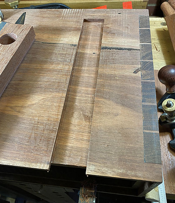
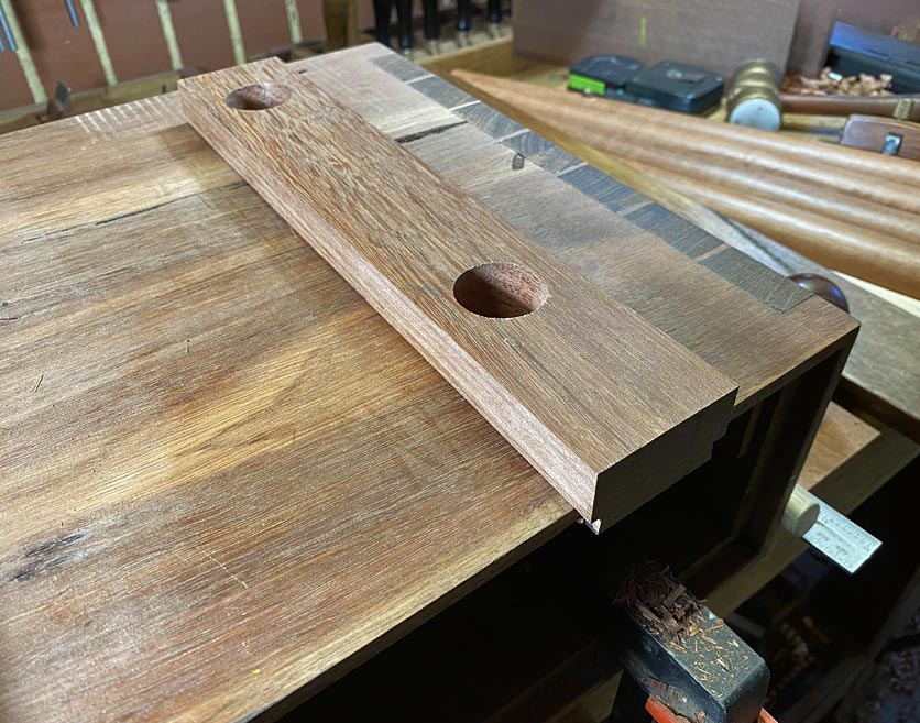
What I need are lipped drawers.The question was whether I make them the easy way, which is by planting (glueing) on fronts. Or, whether I build them out of one piece, which is a lot more work as it requires creating half blind dovetails in a rebate.

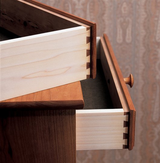
For those unfamiliar with lipped drawers ..

lipped-drawer_5F00_lead1.jpg


This is the work of Christian Becksvoort ...

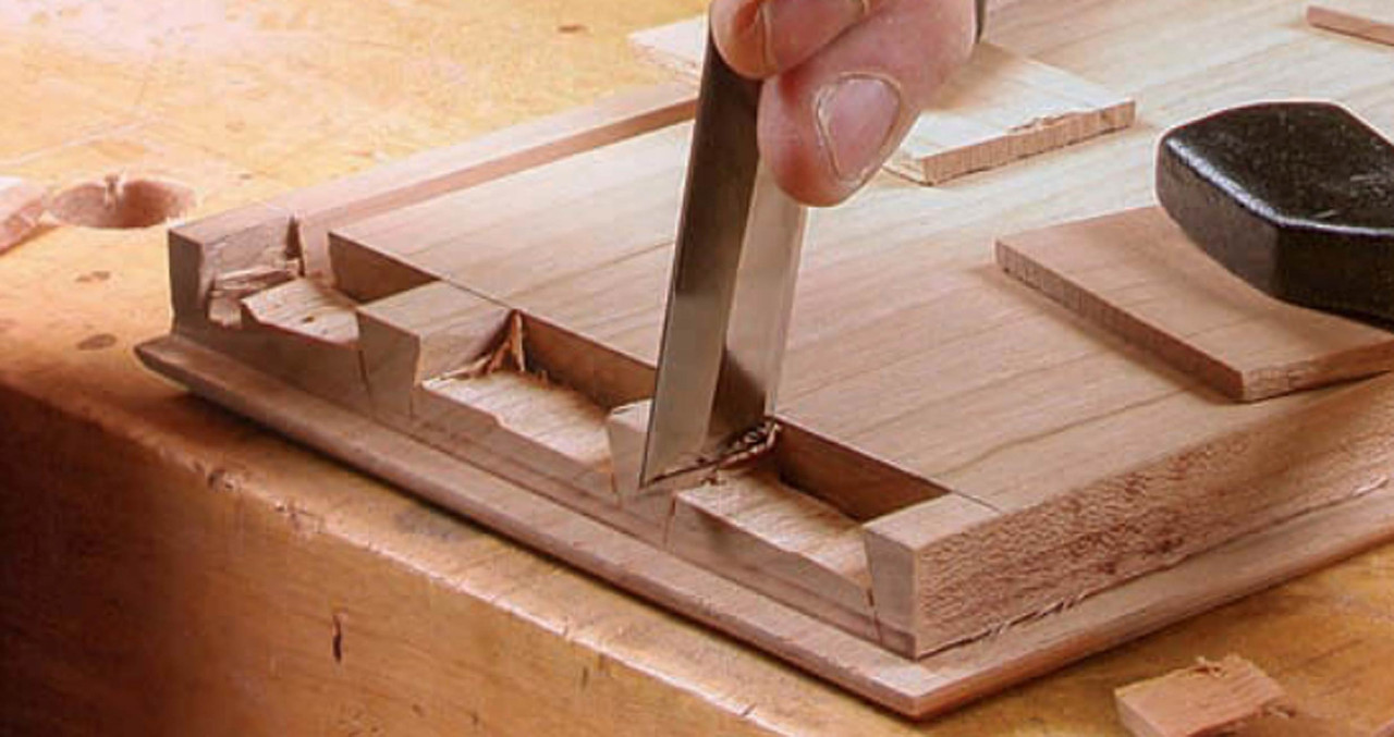
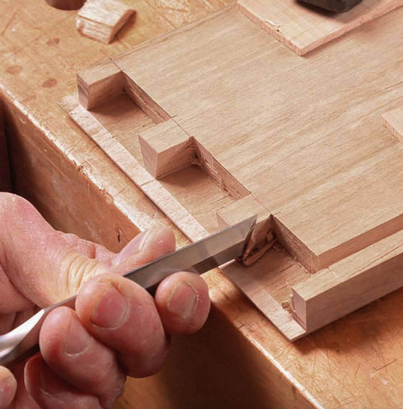
Lipped-dovetail1.jpg


Lipped-dovetail2.jpg


At this point, I am going to do it the hard way and make half-blind sockets in a rebated front. This is similar to building a secret dovetail.

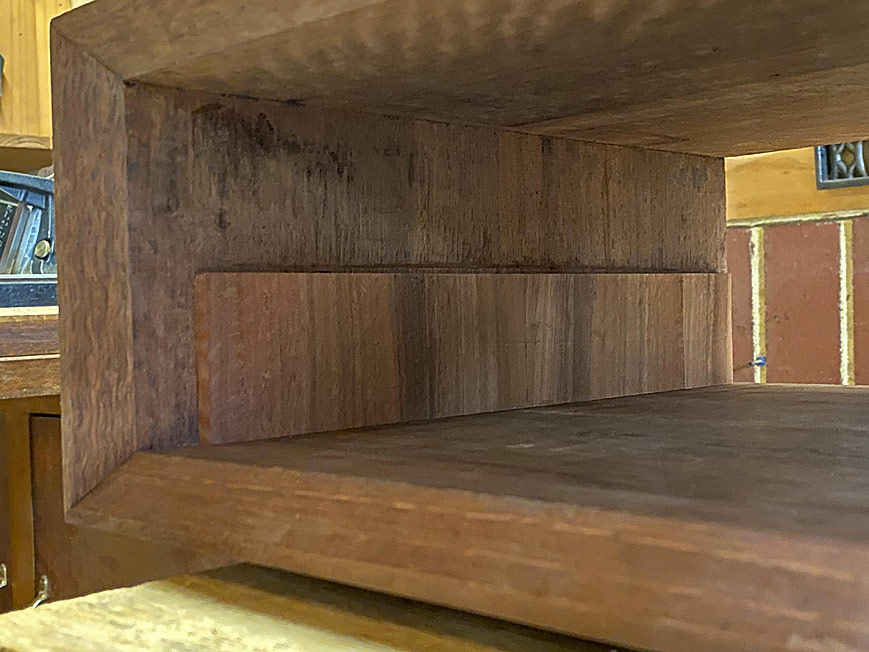
To do this for all the drawers, the insides of the case at each end will require a spacer, essentially a 6mm panel glued to the insides. Each side will be half the thickness of the two middle drawer dividers (each 12mm). The centre dividers will be attached in a dado top and bottom.

Regards from Perth

Derek
 
Will you work a moulding on the fronts, as on the drawers in the pictures? I'd imagine a square edge would let the grain run through all three much better. Plenty of challenges along the way!
 
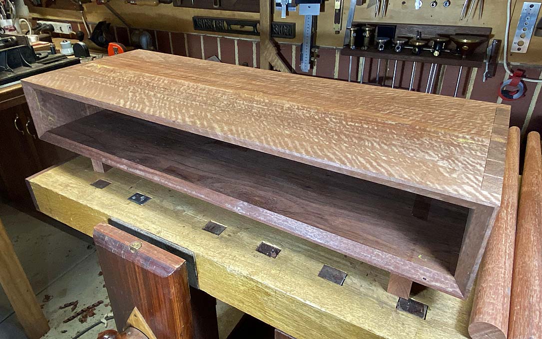
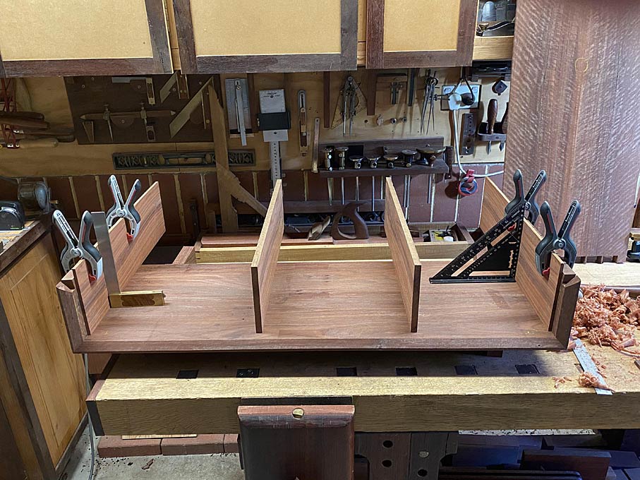
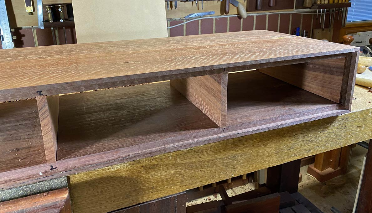
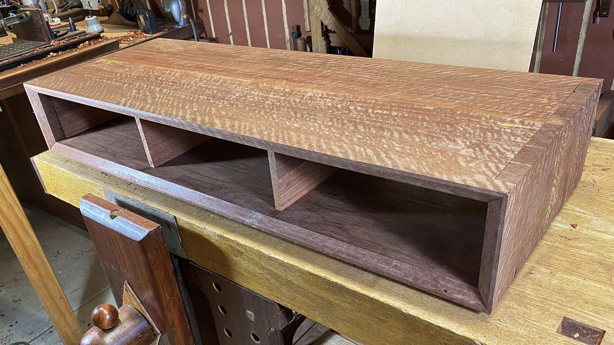
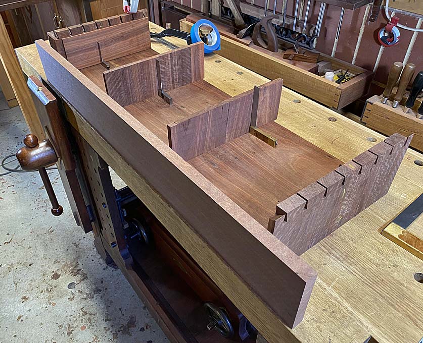
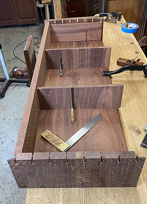
The basic case complete ...

EntryHallTableForANiece4_html_71bad488.jpg


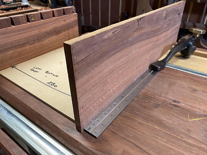
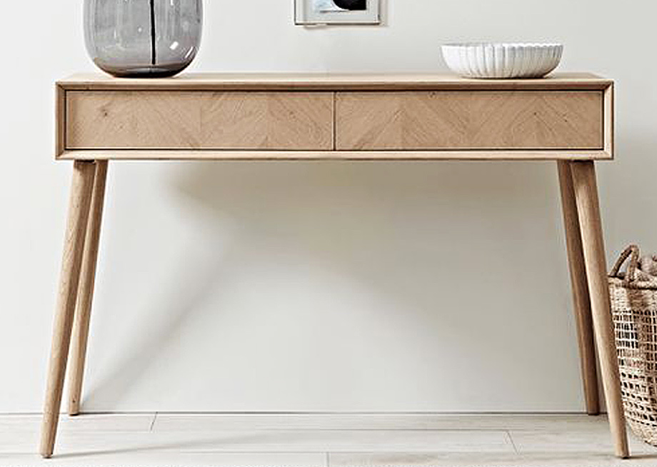
My niece's expressed wish is to have a table front looking as if it was faced by a single board. The original model for this project has two drawers. I did not see this working here since, as their width would be greater than their depth, two drawers would likely rack. Consequently, I decided to build three drawers of equal width (I considered a narrow drawer in the centre, but decided this would be too busy).

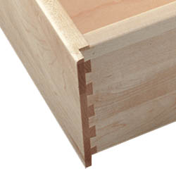
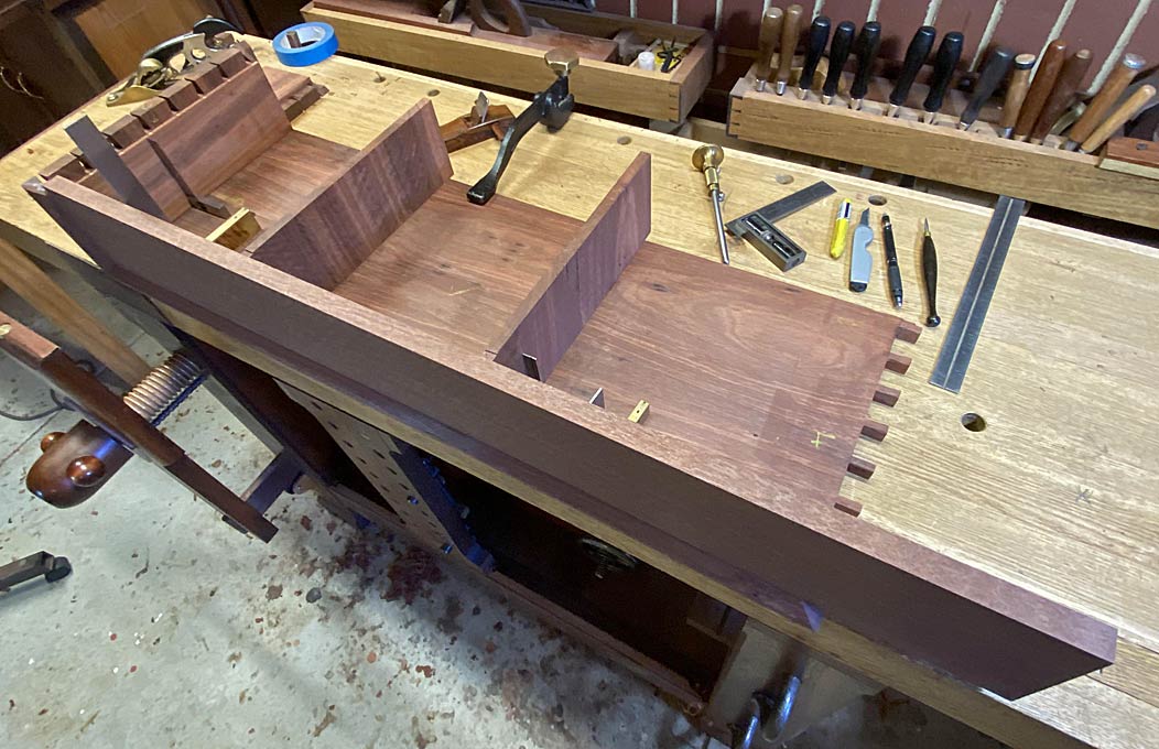
In order that the figure of the drawer fronts would not be interrupted by the drawer dividers, the drawers are to have half-blind dovetailed side lips, such as these ...

DrawerBox_LippedFront_wM.jpg


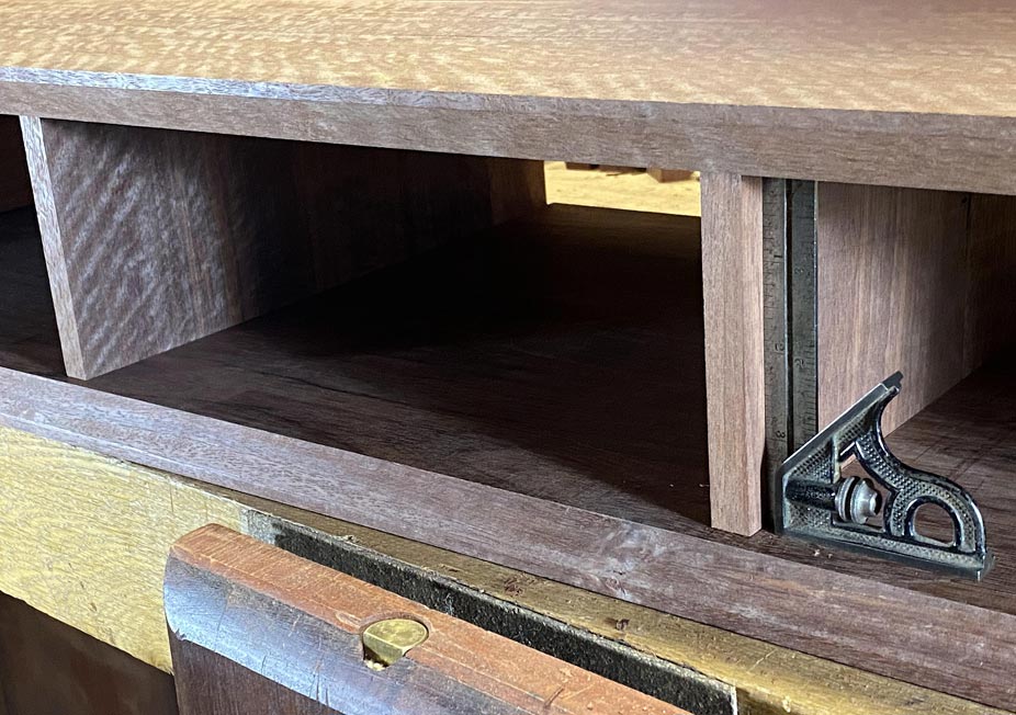
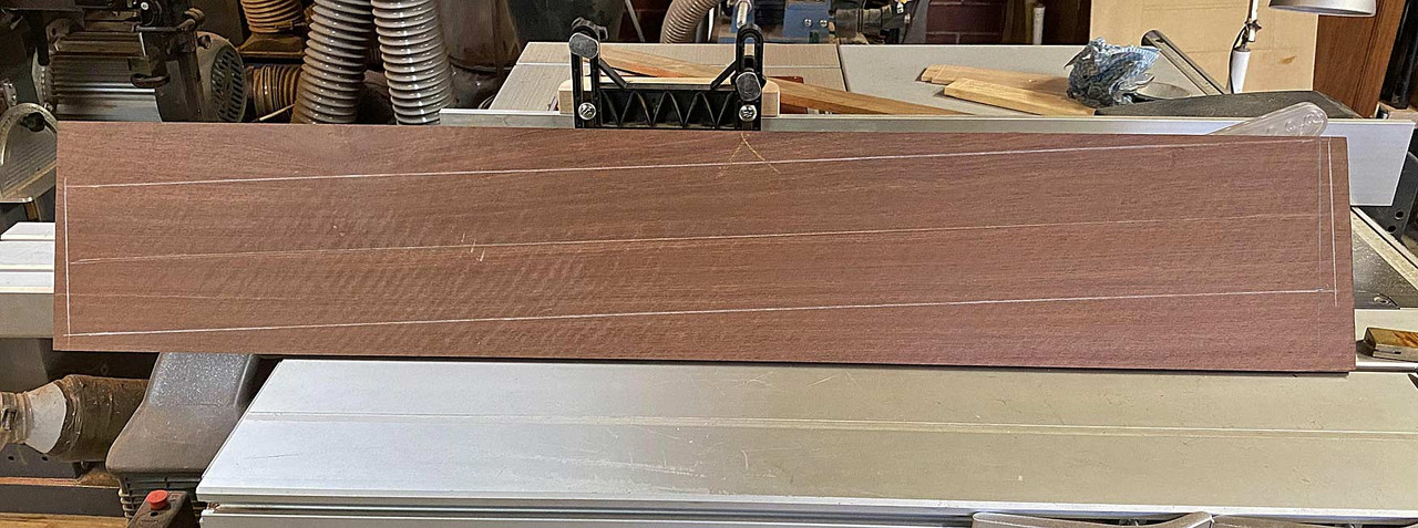
The drawers will each have a side lip of 6mm. This requires a 6mm wide side panel on each side of the case, and two 12mm wide drawer dividers. This will allow three drawers to run adjacent to one another, and the three fronts to be cut from a single board.

The drawer fronts will come from this board ...

Drawer2.jpg


Drawer3.jpg


Below are the panels for fitting ...

1-1a.jpg


It occurred to me later (of course!) that the 6mm end panels could have been made to run with the grain direction of the case. Being the same Jarrah, this would have counted for any expansion/contraction, and there would not be any danger of movement being intrusive. Too late. It's glued.

So I did the next best thing, and planed 2mm off the upper and lower edges. This will permit enough movement, if any (it is a small and thin panel). There will not be any gaps seen as the front edges will later receive edging, which will be used as a depth stop.

1a.jpg


Frankly, the hardest part of this section of the project was accurate marking out of the two central drawer dividers. These need to be both perfectly parallel, and also aligned vertically (the lower panel with the upper panel).

There is a second area that needed to checked, which is important for drawers to work well, and this that the lower panel is flat - that is, does not have any hills. I learned my lesson the hard way about this. All good.

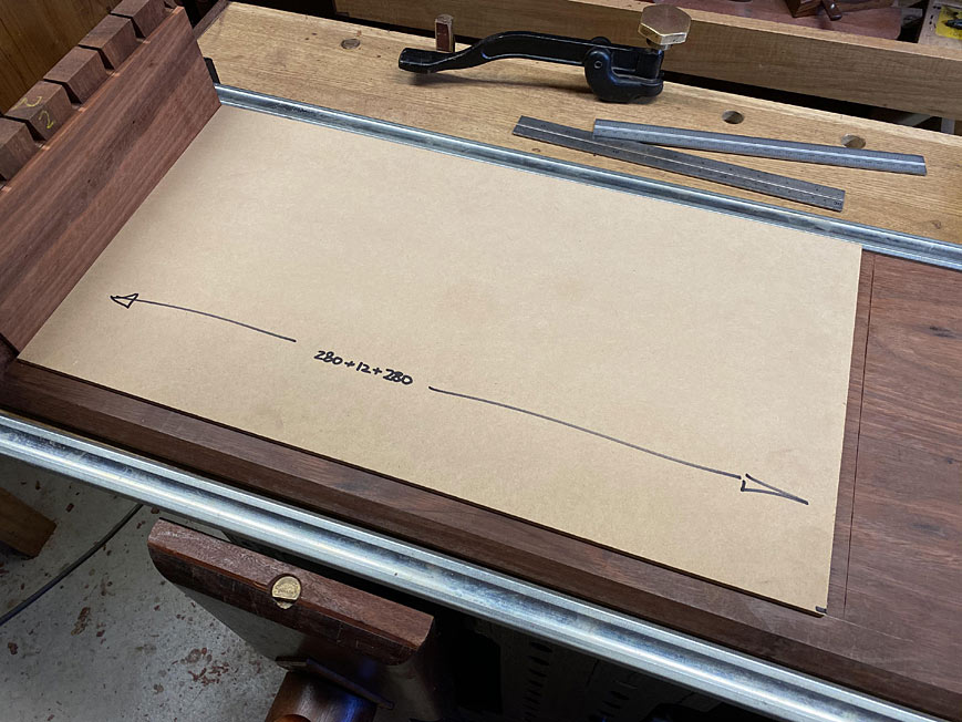
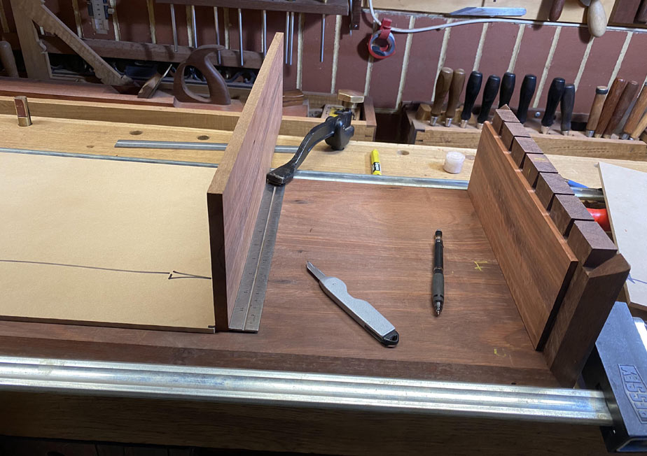
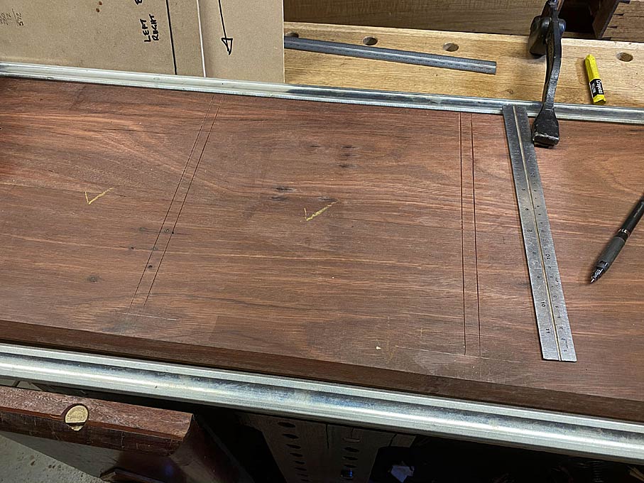
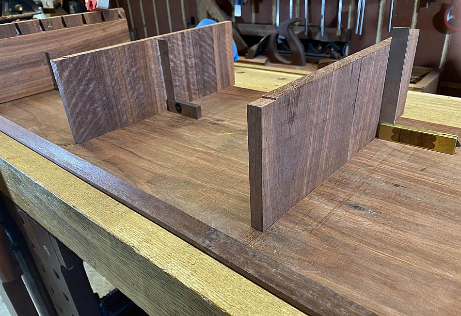
The way I go about marking the dados for the dividers is to make templates for their position. These are used on both the lower panel, as below, and then the upper panel ...

2a.jpg


The process is self-explanatory ...

3a.jpg


5a.jpg


6a.jpg


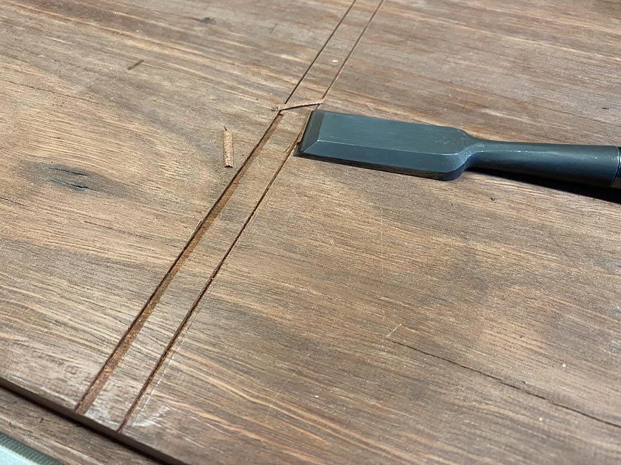
The dados are knifed deeply ...

7a.jpg


Chisel walls cut ...

8a.jpg


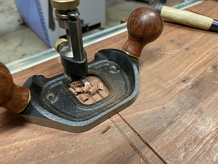
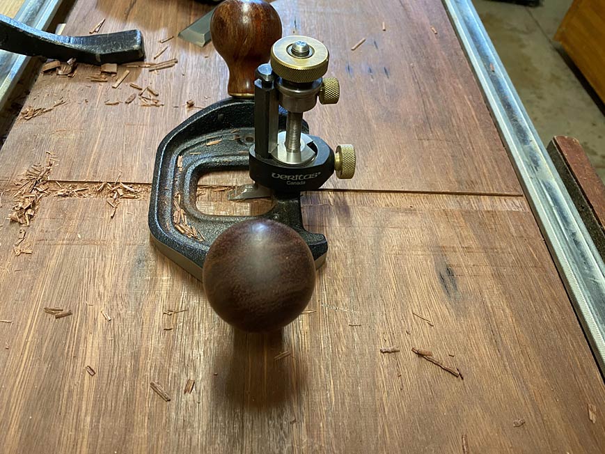
.. and then the waste is removed with a router plane ...

10a.jpg


9a.jpg


The dados are just 2mm deep. That is deep enough to prevent any movement. This process is quick and relaxing (compared to setting up and using a power router).

Once done, the process is repeated on the upper panel ...

12a.jpg


13a.jpg


All ready for a dry fit. The rear of the case ...

1-2a.jpg


... and the front ...

15a.jpg


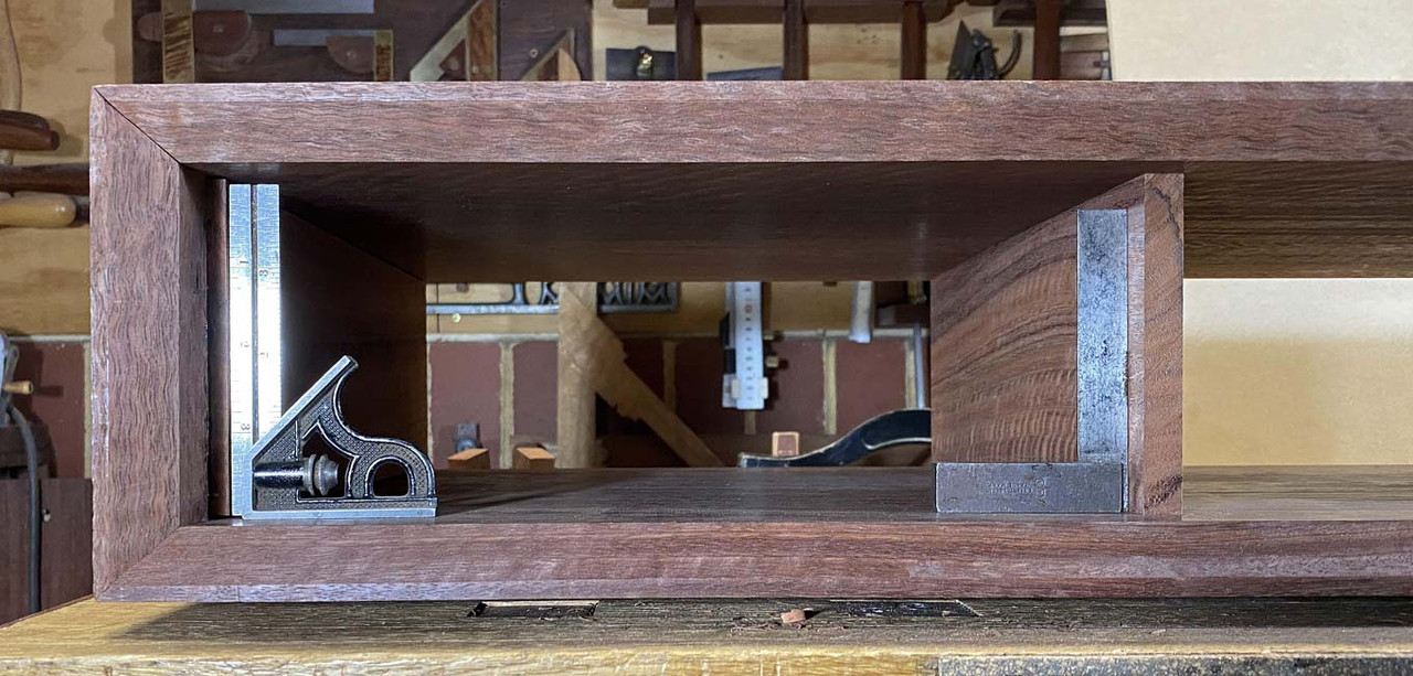
Happily, all is square ...

16a.jpg


17a.jpg


Tomorrow I shall glue it up.

Regards from Perth

Derek
 
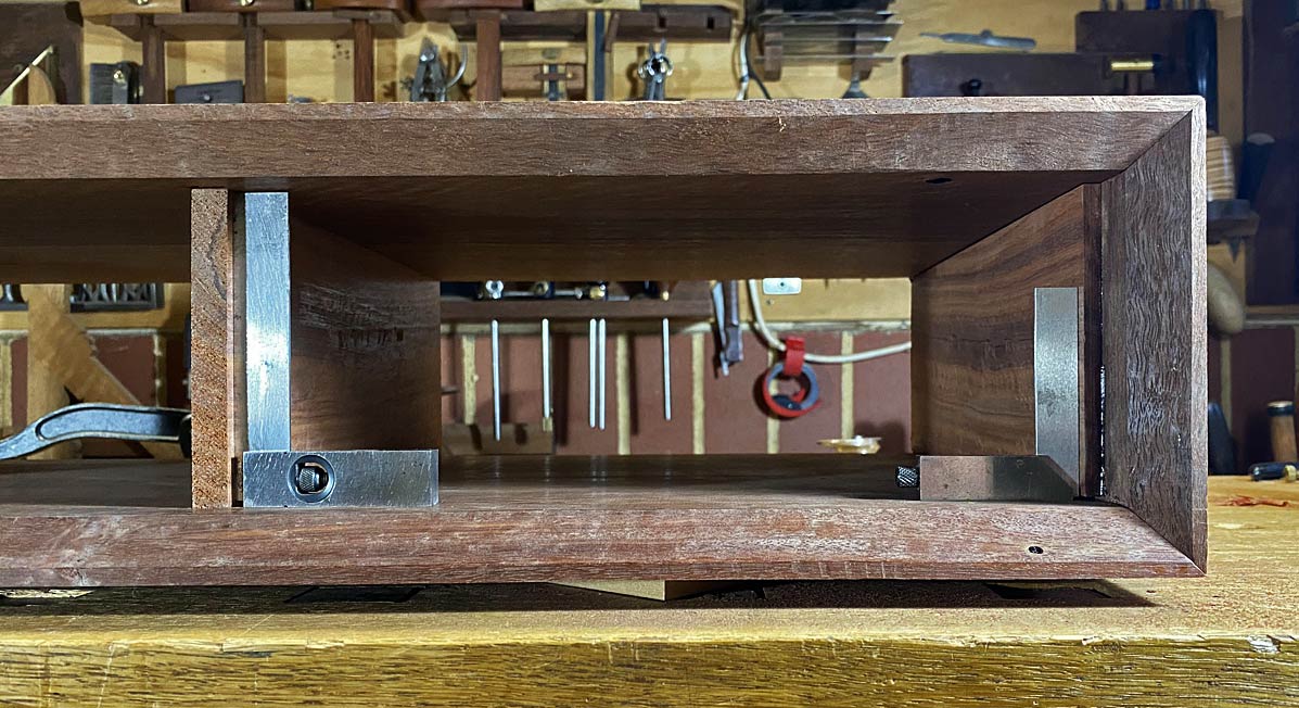
We ended the last session with the drawer dividers installed ...

15a.jpg


Everything was nice and square, but the more I thought about what I had done, the unhappier I became. Such an elementary oversight. I cannot believe I did it, and also that no one pulled me up for it. What was it? Two items:

The first was that the grain for the drawer dividers runs the wrong way. Although the boards are as close to quarter grain as possible, which adds to stability, they will expand vertically. That could cause them to buckle, and then the drawers will not run nicely.

The second is that I could have built in a way to close up the drawer dividers against the back of the (to-be-built) side lipped drawer fronts ... this is to be used as a drawer stop ... at this stage it would be necessary to add a filler. Not good.

So I re-did the drawer dividers. Here is the rear of the case. The drawers are left long on purpose ...

1a.jpg


Provision is made for the dividers to be adjustable in length (to close up with the back of the drawer front). They are given rebates to slide further forward ... it will be necessary that they move around 15mm forward (to within 5-6mm of the opening).

2a.jpg


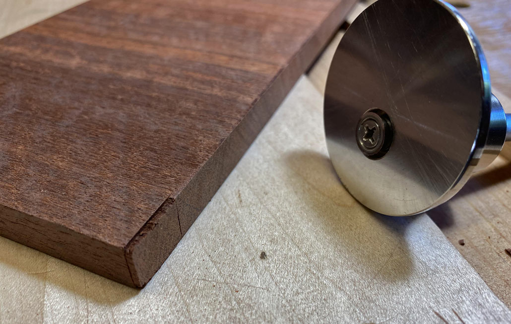
The rebate is 2mm deep (the depth of the dados), and largely created with a cutting gauge. The blade slices away end grain, and the resulting splitting away makes it easy to chop the remainder.

Here are the dividers, further forward than before, and capable of moving a little more still ...

3a.jpg


4a.jpg


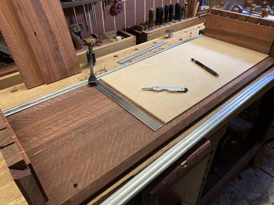
The plan was to glue up the case. However, before this is done, it is wise to fit the drawer fronts across the width (the height will be done at a later date).

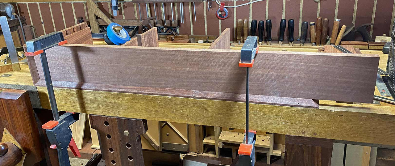
This is the board for the three drawers.

5a.jpg


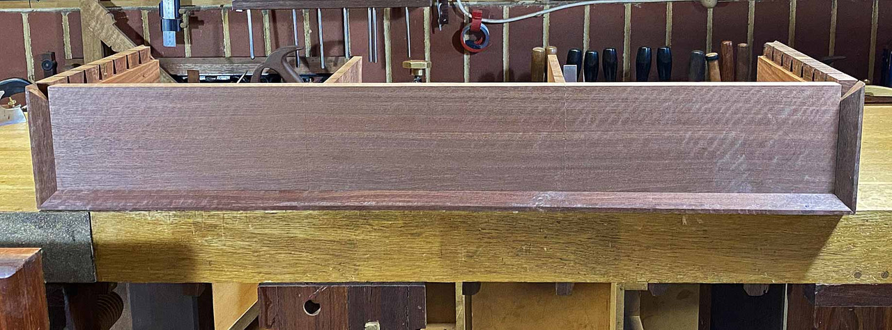
Removing one end, the board is set on the case ...

6a.jpg


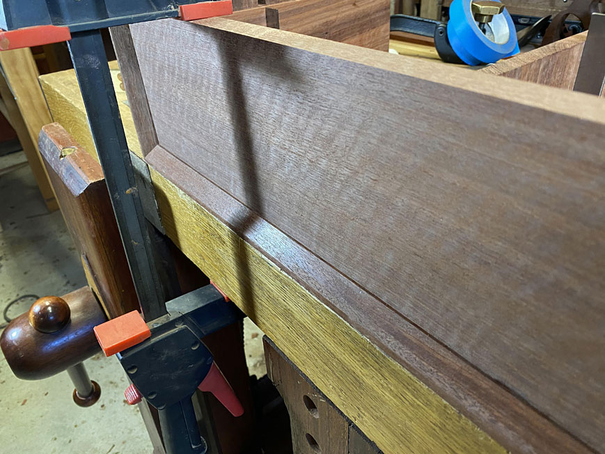
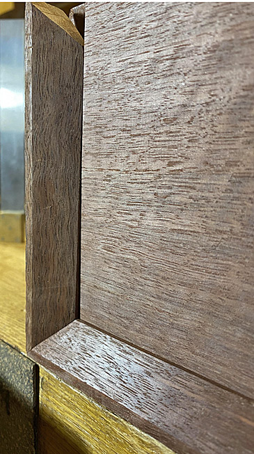
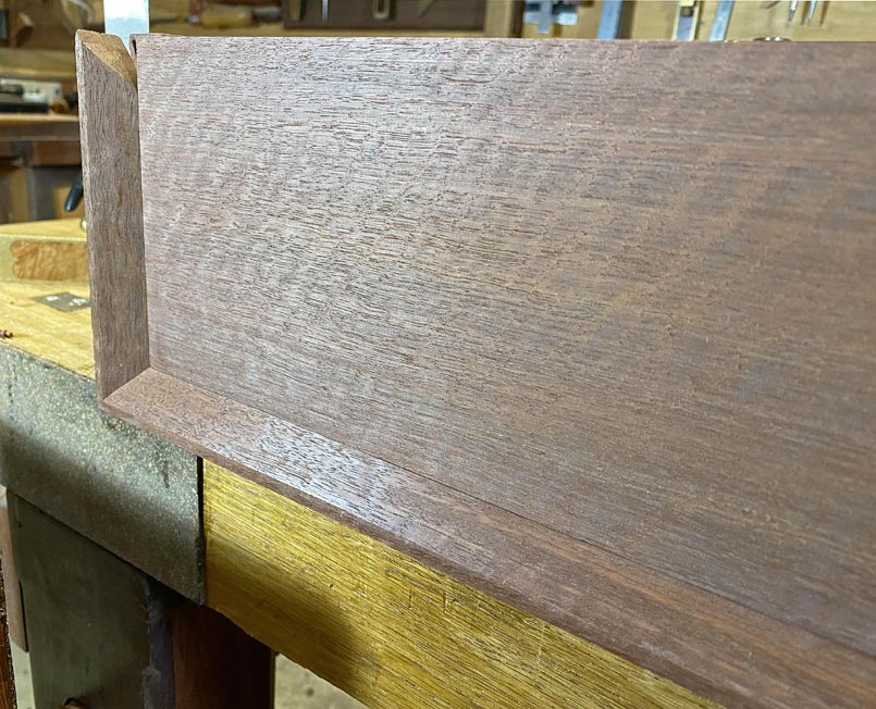
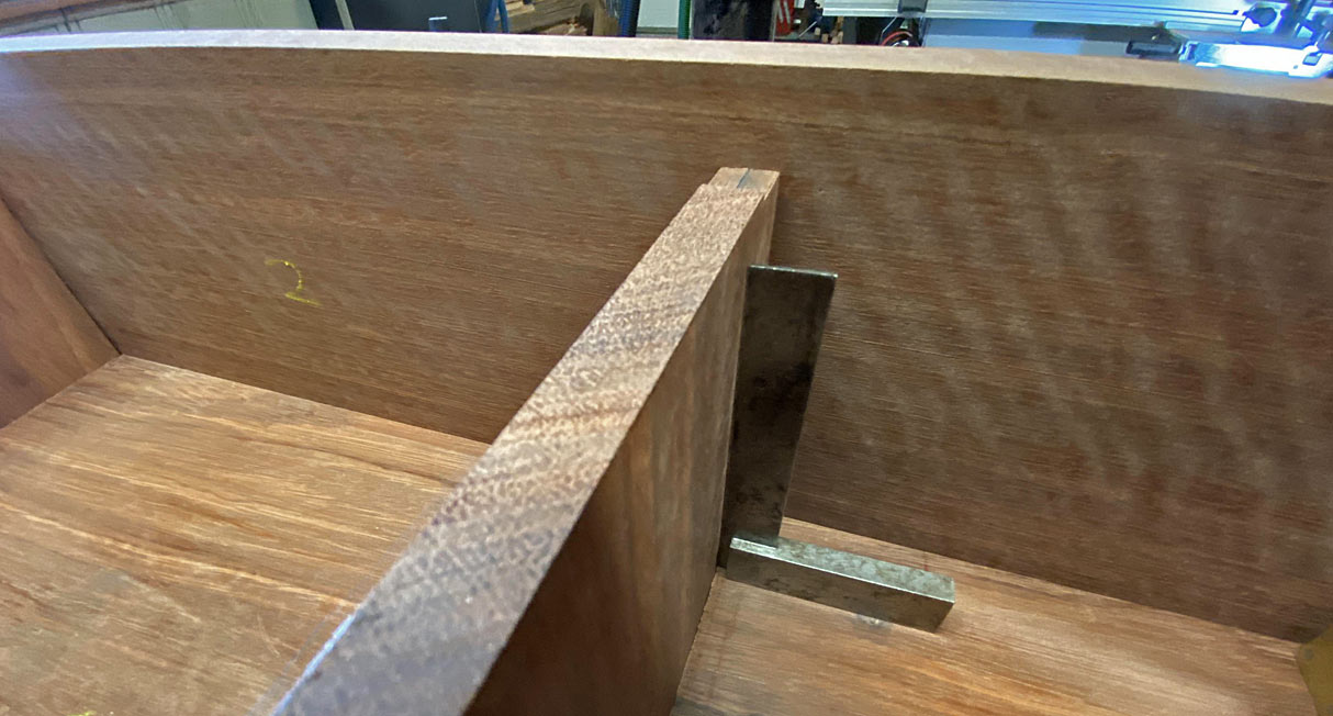
It is now apparent that the front of the bevel, where it meets the drawers, is not straight. It is possible to see a small amount of flat ...

7a.jpg


This is especially noticeable in this corner ..

8a.jpg


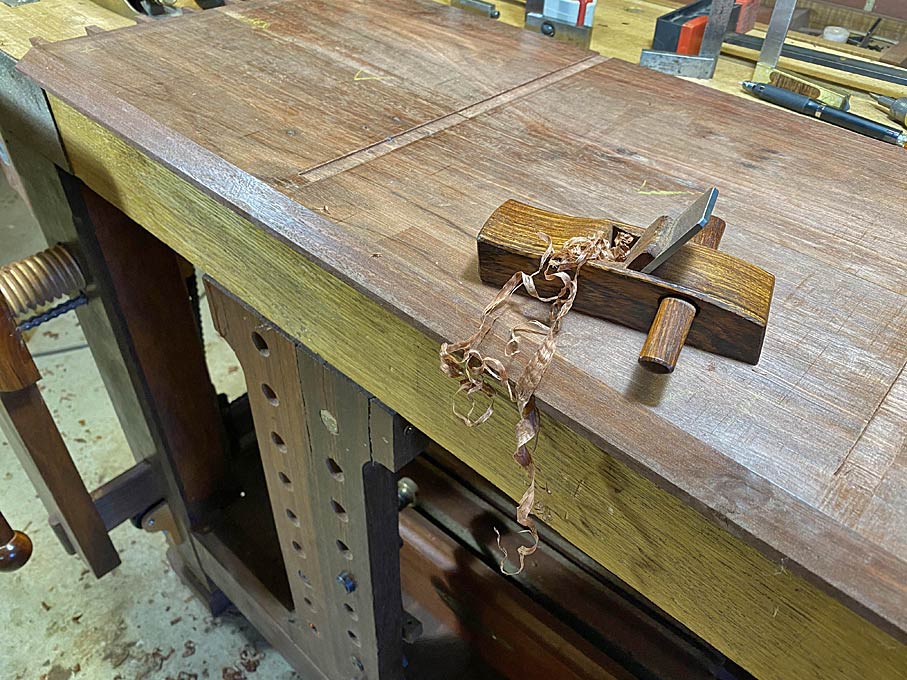
This is fairly easy to remedy ... mark with a pencil, and then plane away the pencil marks ...

9a.jpg


Perfect now ...

10a.jpg


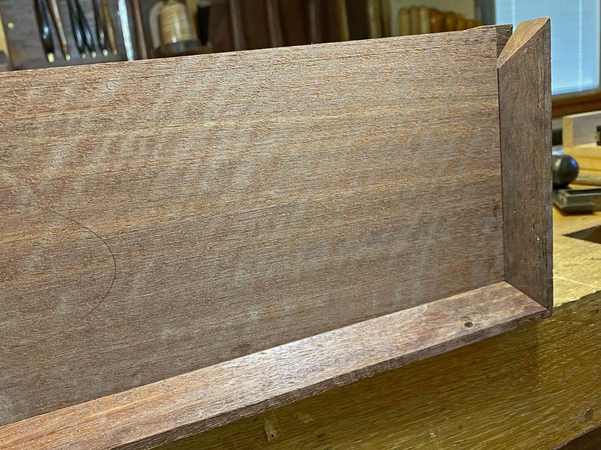
The other end needs no more than a smidgeon removed ..

11a.jpg


The upper side is now treated the same way. Interestingly, this needs no work at all.

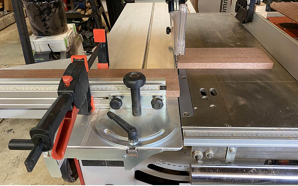
Time to saw the drawer fronts to size.

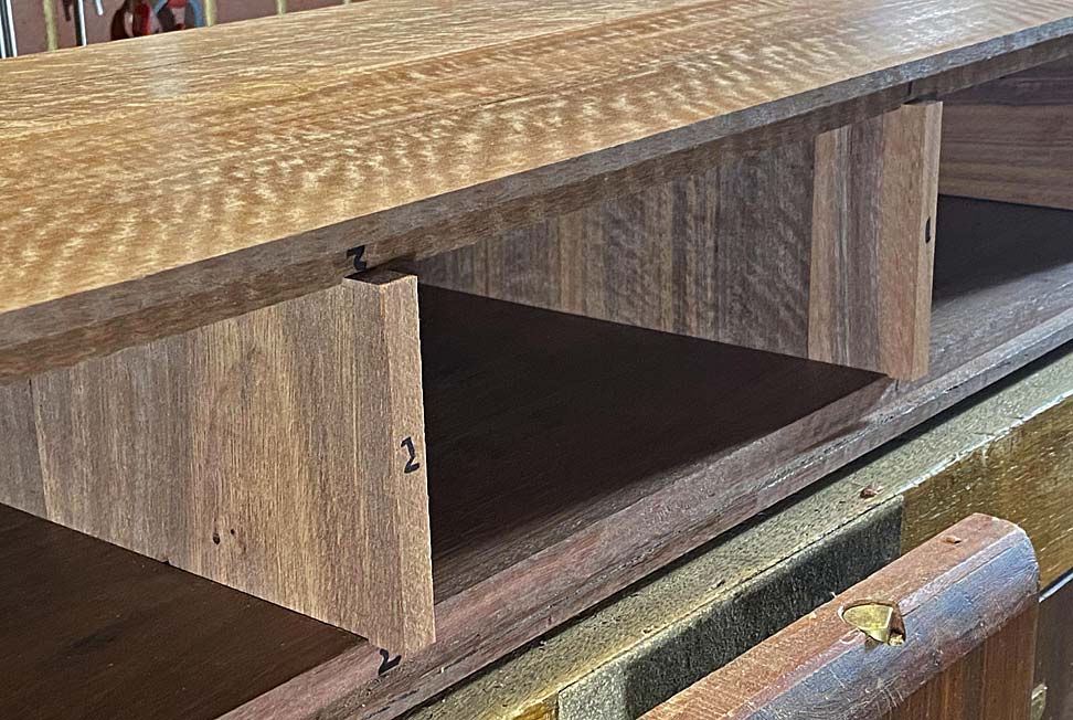
First step is to mark the middle point of each divider (since the lips will share the divider). The mark can be seen in the rebate ...

13a.jpg


The drawer board across the front ...

14a.jpg


Transfer the mark, and then saw the drawer front ...

15a.jpg


This process is repeated. Here are the three sequential drawer fronts. You can just make out the breaks ...

16a.jpg


17a.jpg


I am happy with this.

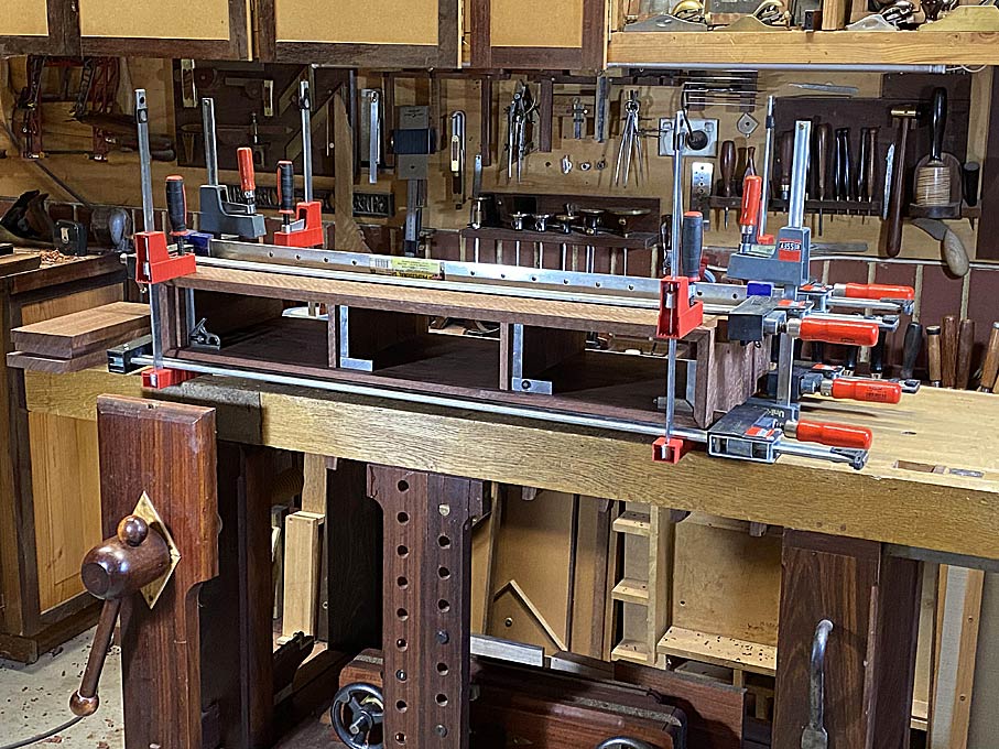
And so, finally, the case is glued up (Titebond Liquid Hide Glue - reversibility and long open time). Looking like a trussed up fowl ....

18a.jpg


Regards from Perth

Derek
 
Phew, that was a good spot about the grain direction! I can see how it happened, you made them to match those horizontally aligned pieces at the ends, but that would have bugged you I'm sure if you'd carried on. I'm slightly surprised you didn't remove and re-do the end pieces at the same time, but that really is too late so I shall keep quiet.

And presumably you trimmed the backs of the dividers before they were glued in place?

Nice adjustments to the mitres as well - did you choose that plane because the extra length before the iron makes it easier to locate on the bevel?
 
Thanks Andy.

I did not remove the end pieces since they had already been given the necessary adjustment - providing a gap for expansion.

The little HNT Gordon palm smoother is the size of a small block plane and have a 60 degree cutting angle. It was chosen because it was small enough to do this delicate planing, and would cop with the very interlocked grain.

Regards from Perth

Derek
 
The case was glued up yesterday, with everything tight and square as one could wish, but I did not sleep well. I was haunted by the thought that there was a problem that would come to a head some time in the future.

17a.jpg


If you look at the grain direction of the two centre drawer dividers, you notice that the grain is vertical. That is the way it should be. Wood moves, expands and contracts. It does this in reaction to moisture in the air. When it moves, it does so across the grain. That is why solid wood drawer bottoms have grain across the width - allowing the drawer bottom to move towards the back of the drawer, rather than towards the sides (where it will be blocked and then buckle).

These drawer dividers will be butted up against the rear of the drawer lips and act as drawer stops. The front third of the divider will be glued in the dado, forcing any expansion towards the rear of the case. All good.

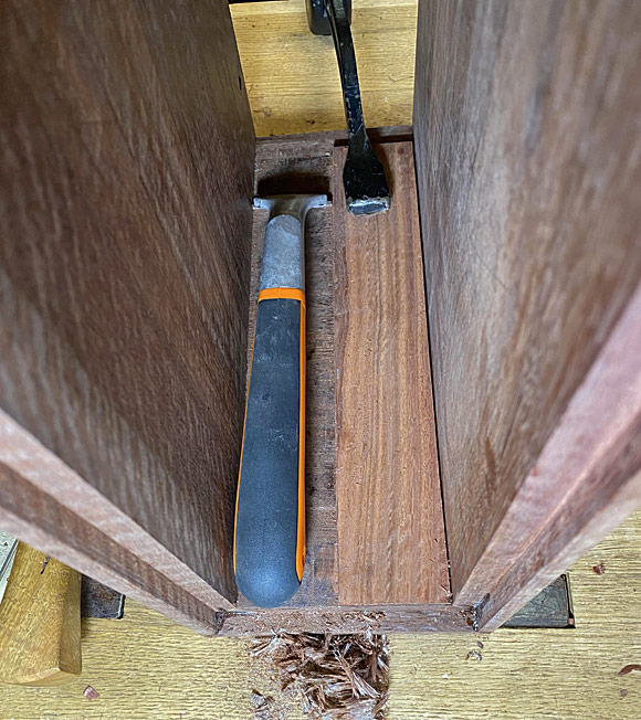
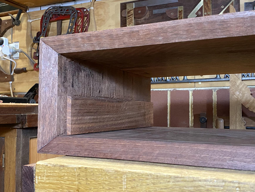
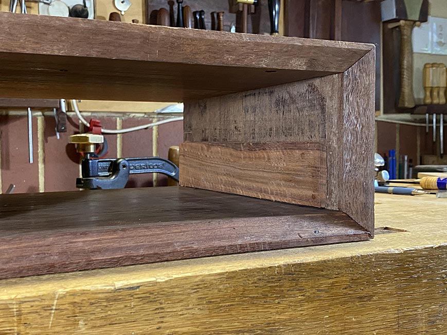
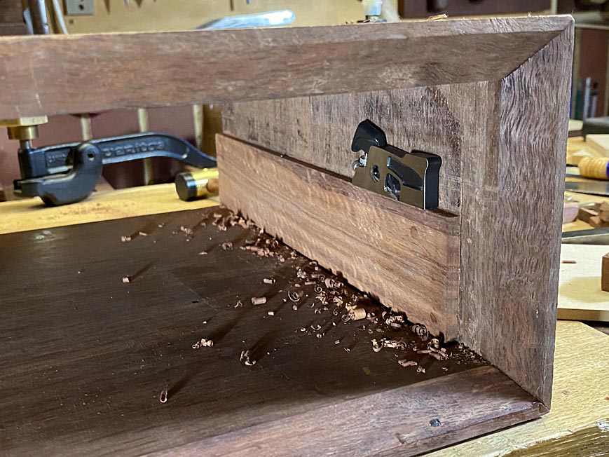
The two spacers at the inside ends of the case have the grain running horizontally. I glued this in before I realised that I had cut them this way. I had done the same with the internal dividers, but re-cut them, as shown in the previous article. The end spacers will expand vertically, and to allow for this, I provided a 2mm gap below and above the panels. That is what kept me awake.

The end spacers are 6mm thick. The case, to which they are glued, is 20mm thick and about 40mm wider. Initially I was concerned that the spacer would be overwhelmed by the case moving, and buckle. Having thought some more about this, I am no longer concerned that this will occur. Why? Because movement in the case would instead "stretch" the spacer length-wise. I started to breath again.

In the end, I decided to reduce the height of the spacers by half. This would allow them plenty of space to expand, when necessary, as well as reducing their impact inside the case.

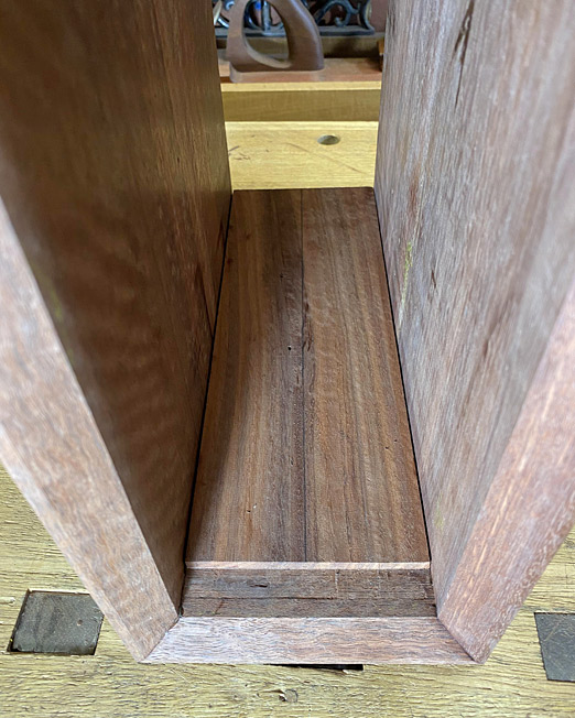
Here is one side ...

1a.jpg


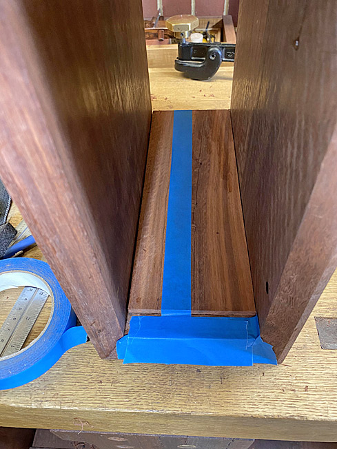
Taped for visibility and protection ...

2a.jpg


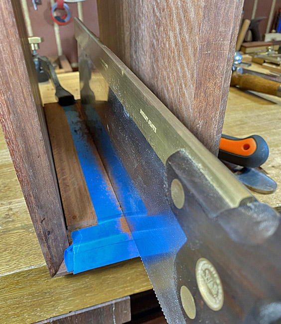
The saw is a 16" Wenzloff & Sons tenon saw (10 tpi) ...

3a.jpg


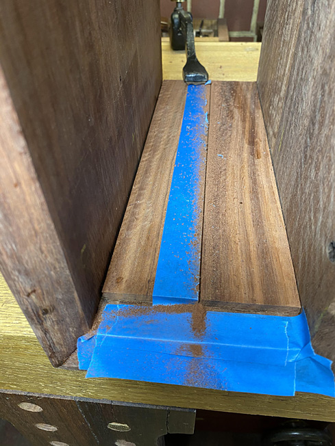
Three kerfs ...

4a.jpg


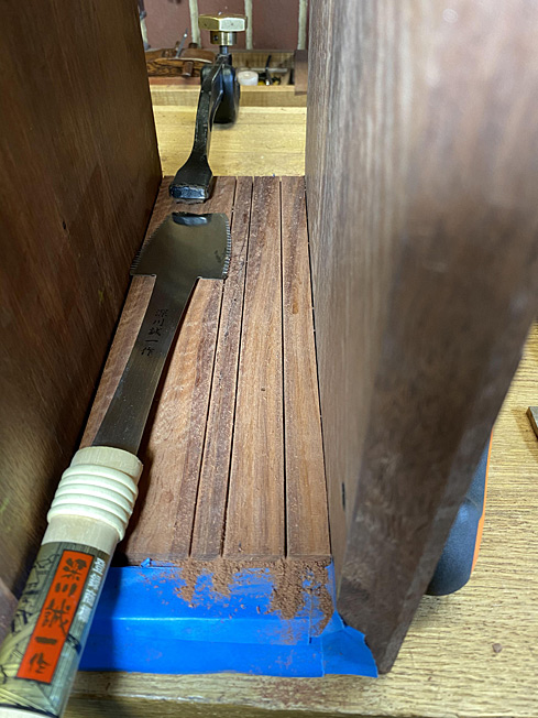
Deepened with a Japanese Azebiki ...

5a.jpg


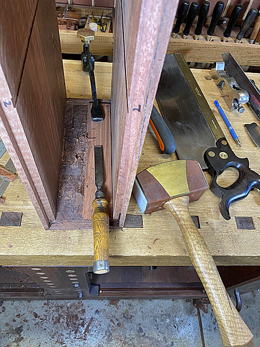
... and split out with a firmer chisel ...

6a.jpg


A Bahco carbide scraper cleans up ...

7a.jpg


The result ...

8a.jpg


9a.jpg


Final cleanup was aided by the only shoulder plane that fitted inside the space :) ...

10a.jpg


Regards from Perth

Derek
 
Yet another benefit of hand tools. I don't know of any power tool approach that would have solved that one.

I hope you are sleeping easier now!
 
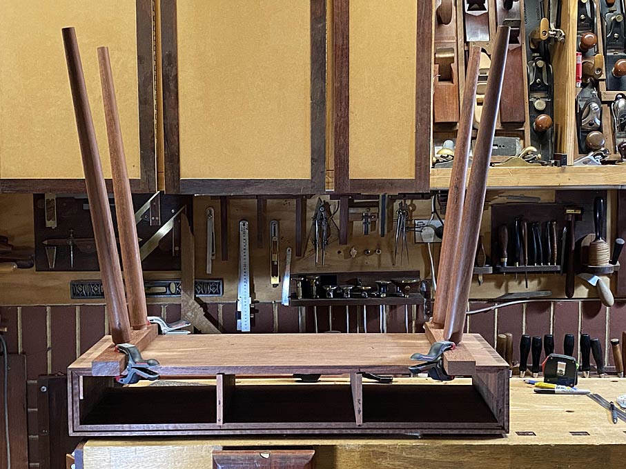
As a reminder, we are building a version of this table ...

EntryHallTableForANiece2_html_m698578a5.jpg


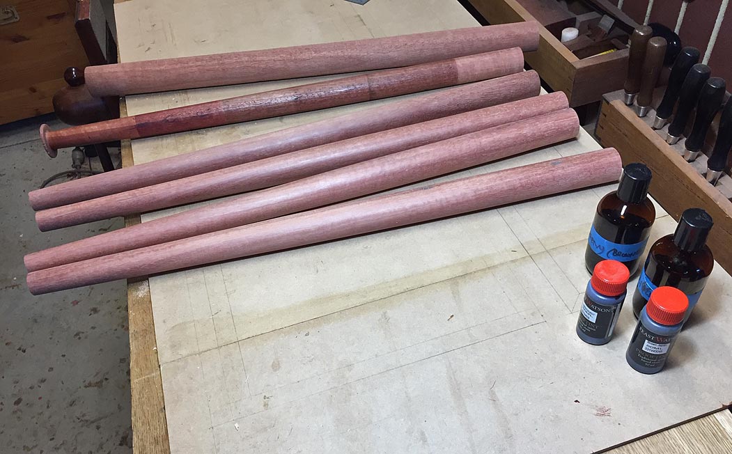
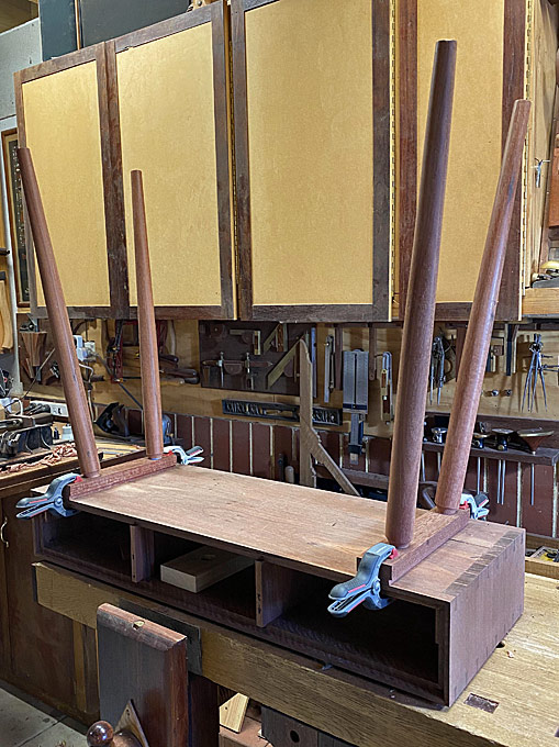
The plan is to attach the legs, which were made near the start of this project.

EntryHallTableForANiece2_html_m34dbb245.jpg


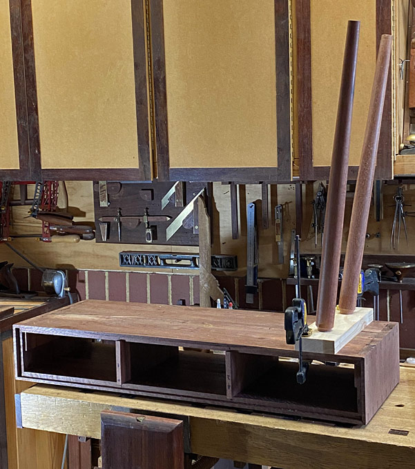
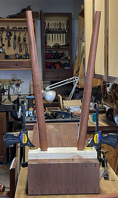
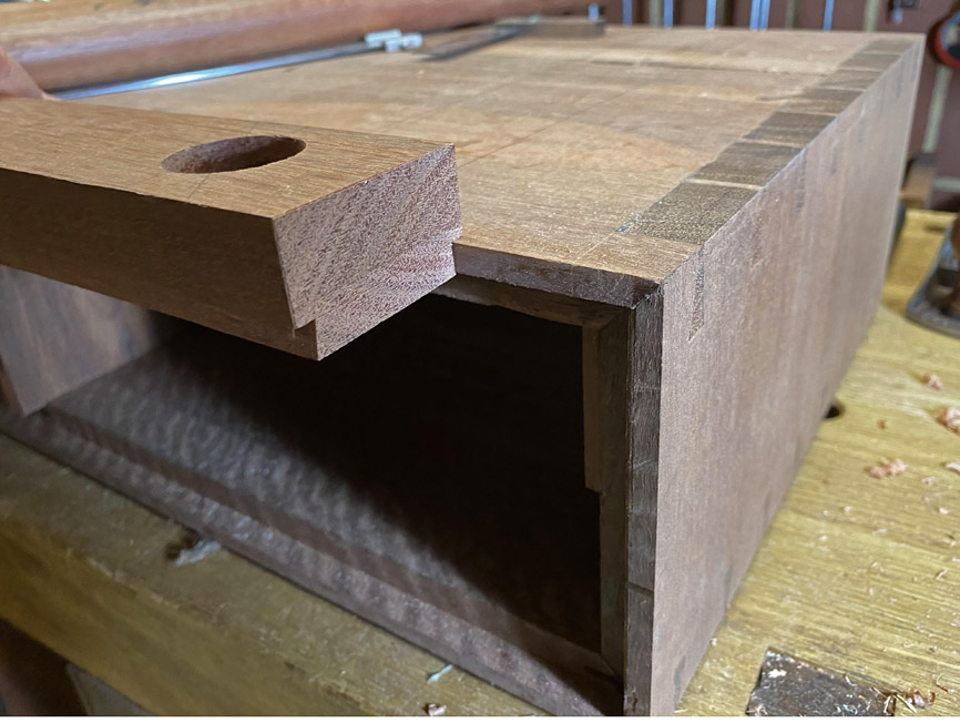
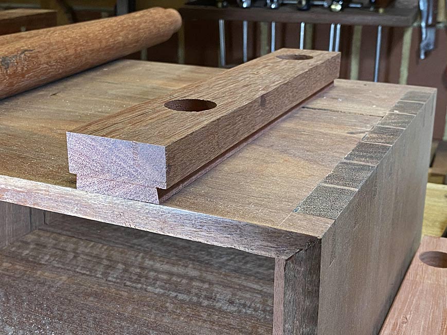
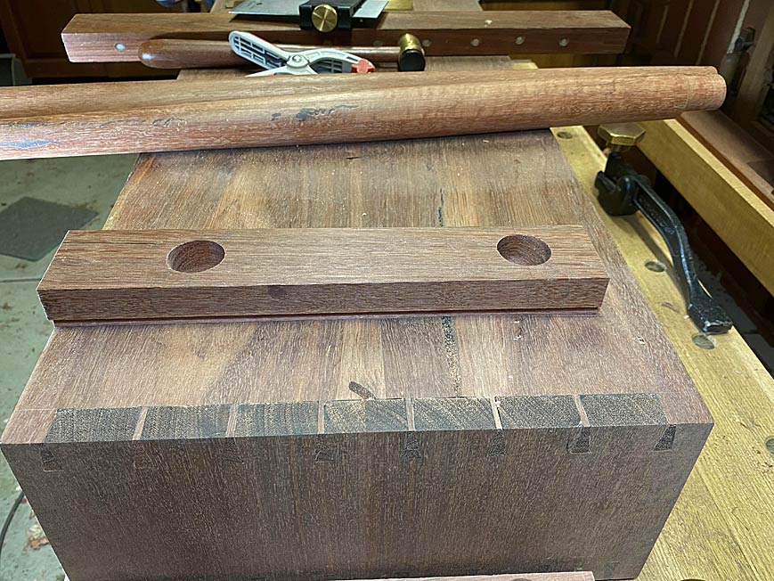
The attachment method is by inserting the legs into compound angle mortices in a base, which will be fixed to the carcase with a tapered sliding and stopped dovetail. We don't mess about here! :)

It will be necessary to do this over two articles, the first being the base for the legs, which will be dovetailed (tails). The second will be the socket (pins) for the base.

Before we begin, I want to mention what I did at the end of the last session. I had replaced the central drawer dividers as the grain ran in the wrong direction. The spacers at the ends also did so, and my response was to cut out half the spacer ...

17a.jpg


Well, I fretted over the end spacers, and just could not leave them this way. Encouraged by the way the halves had come out cleanly, I removed the remainder and replaced the spacers with correctly grained versions ...

2a.jpg


OK, onto the leg base ...

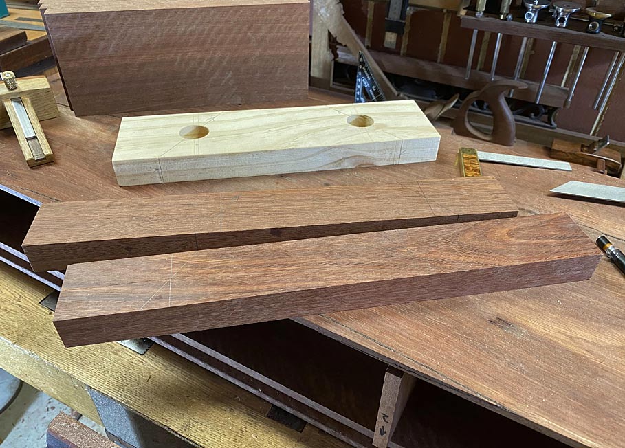
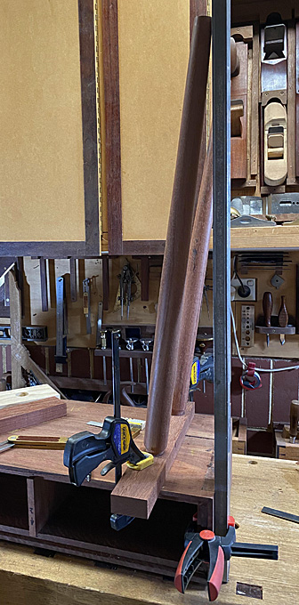
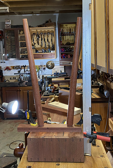
I spent a while playing with angles for the legs, and finally accepted this (mocked up base) ...

5a.jpg


6a.jpg


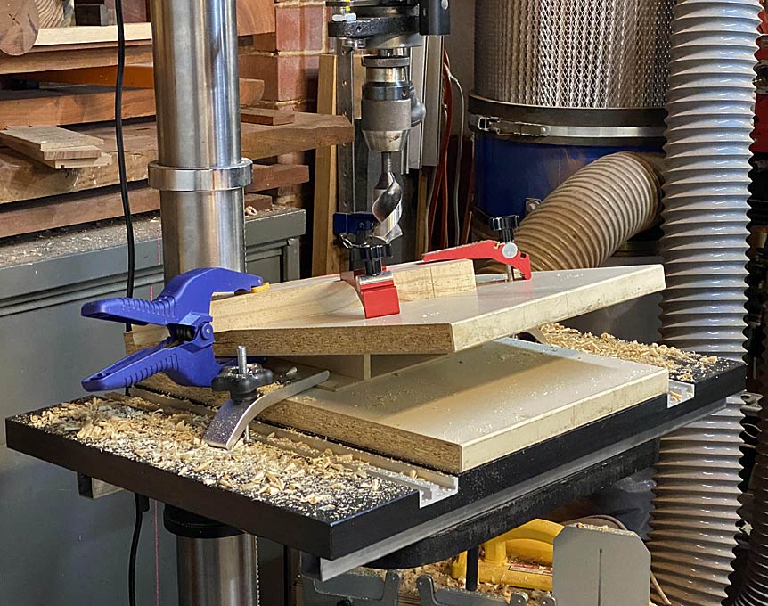
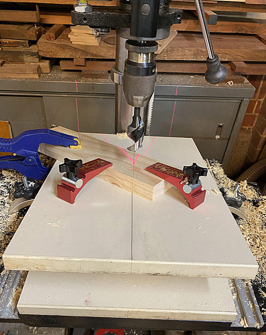
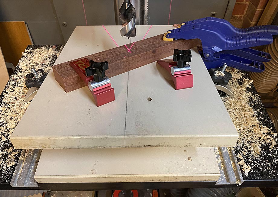
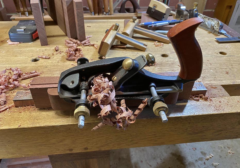
I have drilled angled mortices with a brace on a number of occasions. This time I decided to used a drill press and some Japanese Star-M augers, which are specially designed for this type of work (no lead screws). I built a 10 degree ramp for the resultant angle. The auger is 30mm ...

3a.jpg


[
4a.jpg


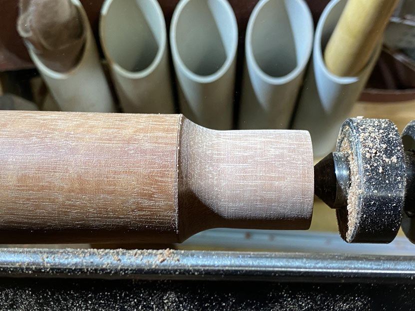
The tenon is straight, but the mortice will receive a slight reaming, and the tenon will be glued and wedged. This is probably overkill since the weight of the case rests on the legs.

7a.jpg


These are the bases for the legs. The final prototype is at the rear ...

8a.jpg


Drilling the bases ...

9a.jpg


The design requires that the legs do not go over the boundary of the case (to avoid tripping over them) ...

10a.jpg


11a.jpg


This is how they should be ...

12a.jpg


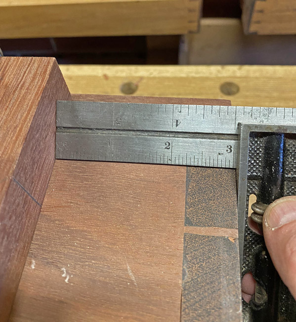
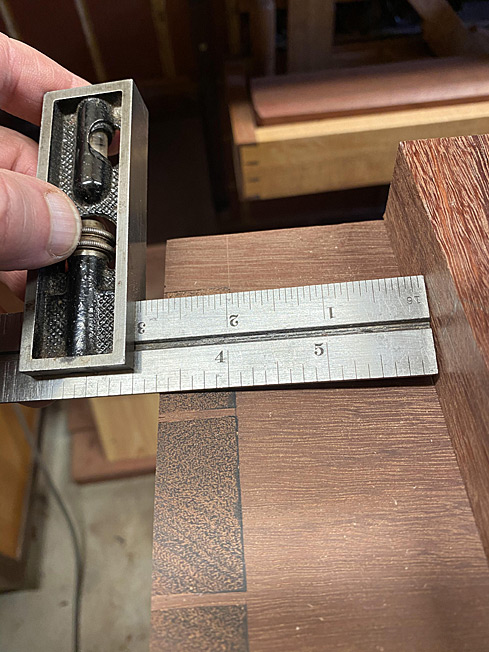
There was a small dilemma: The base at one side measures 3" from the end ...

13a.jpg


... and the other side measures 1/4" further ...

14a.jpg


I could not work out how this occurred. The angles are the same. In fact, I made another set of bases, and the same error showed up again - exactly the same!

So what to do? Actually, the decision was obvious after a little think - make the bases the same. What is more likely to be noticed is if the bases are different distances from the sides. No one will notice a 1/4" difference where the legs hit the ground. So be it.

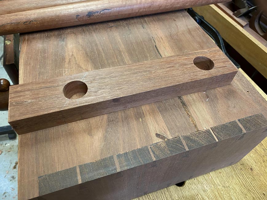
This is one of the bases for dovetailing ...

15a.jpg


First step is to remove a 2mm taper from one side. The taper will be on the inside of the base, with the outside parallel to the side of the case.

Taper line drawn ...

16a.jpg


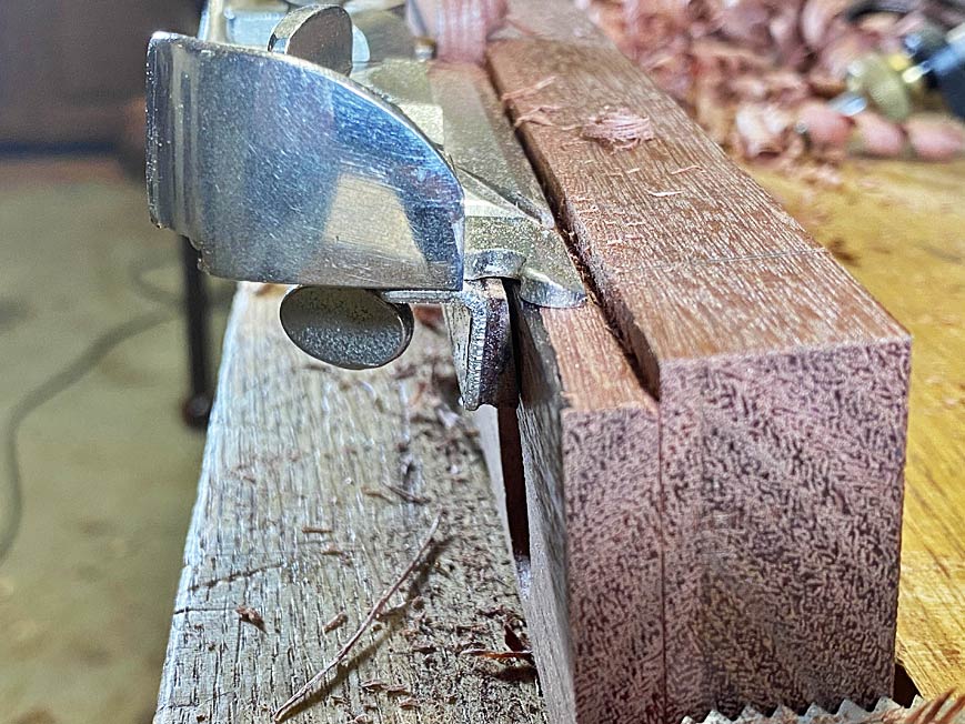
Easiest way to do this is with a #604 smoother ..

17a.jpg


This is the one end of the base ...

18a.jpg


.. and this is the other end ...

19a.jpg


mmmm .... 0.39 mm oversize. What to do ...? I'm kidding :)

The dovetails will be 7mm deep. A shoulder was planed with a rebate plane ...

21a.jpg


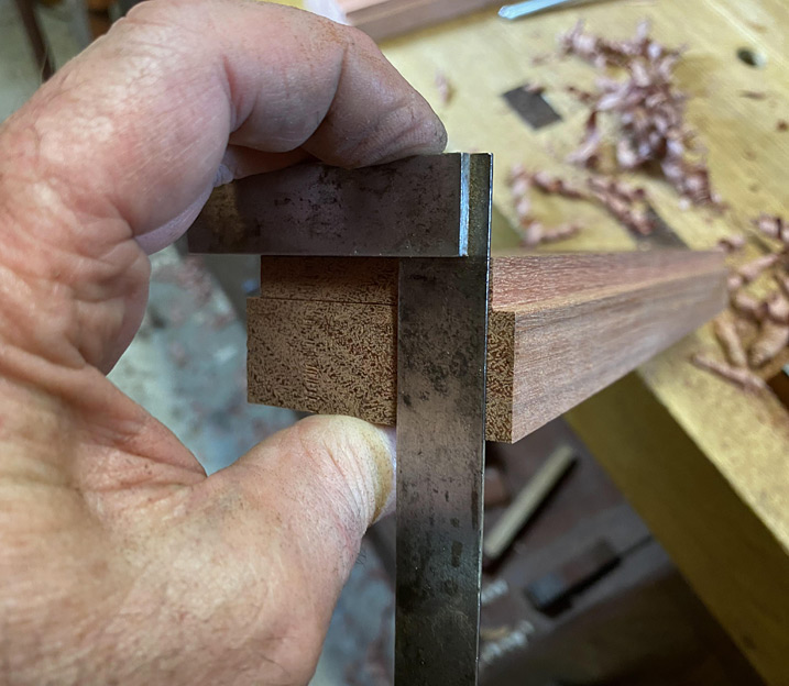
The squareness of this rebate is important, so check ...

22a.jpg


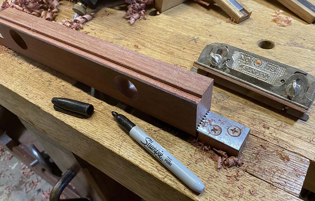
The dovetail is now to be created, and the preparatory step is to colour the outer edge of the rebate with a sharpie. This will warn that the planing does not lower the external edge of the rebate.

23a.jpg


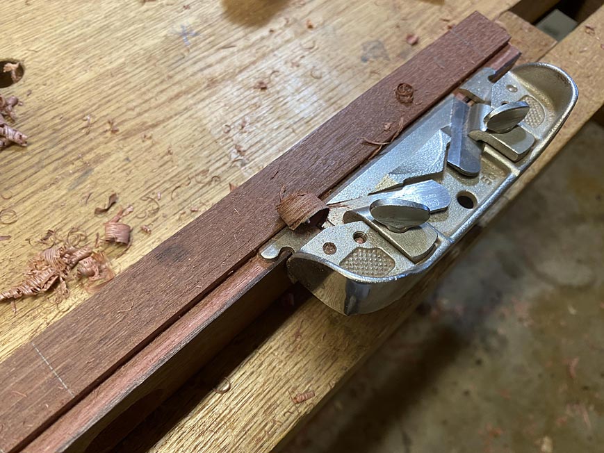
The dovetail is created with a modified Stanley #79 edge plane ...

24a.jpg


The fence has a 1:6 ratio wedge ...

25a.jpg


Details of this dovetail plane here: http://www.inthewoodshop.com/ShopMadeTo ... ley79.html

The result of planing. That is a 1:6 dovetail marker ...

26a.jpg


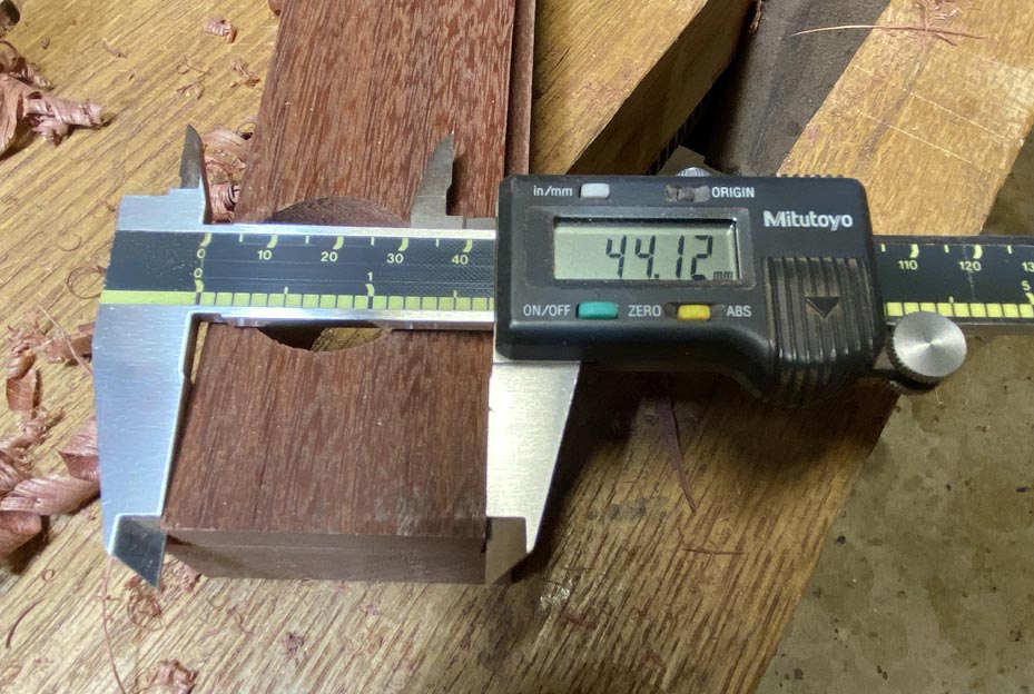
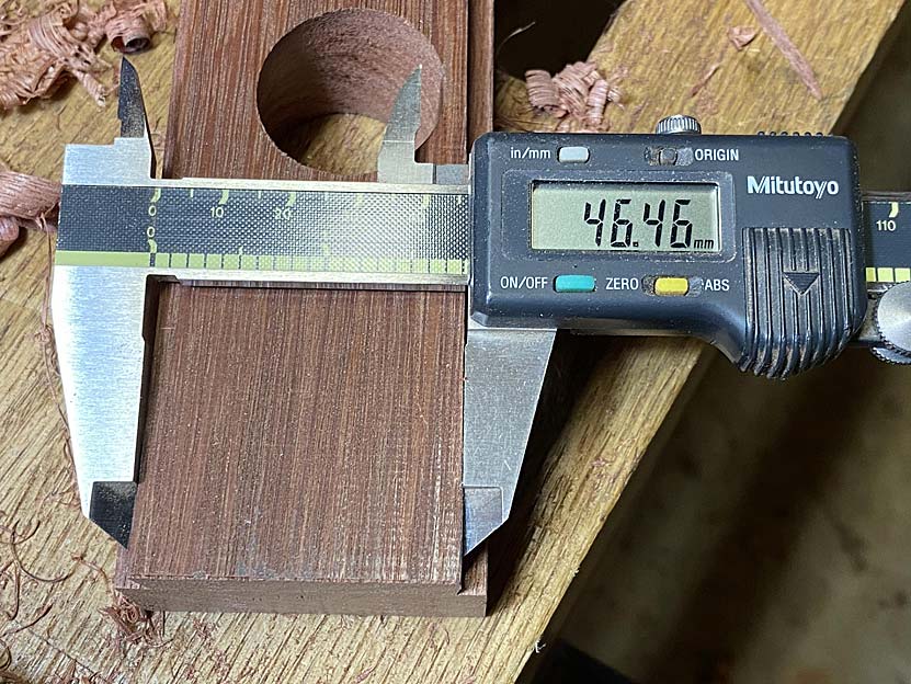
So what are the numbers for the taper? This will give an indication of the accuracy of the joint.

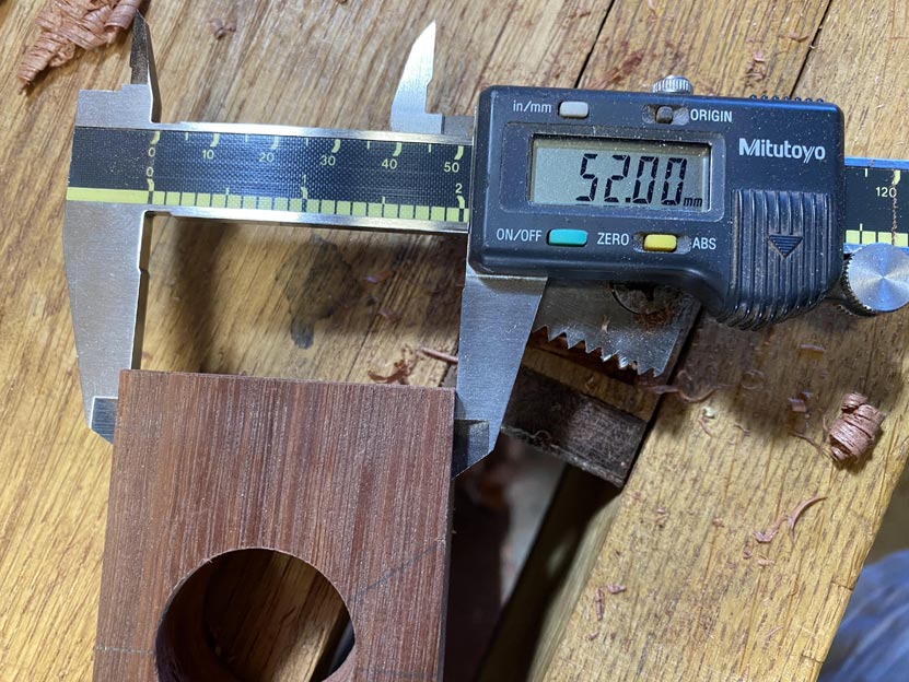
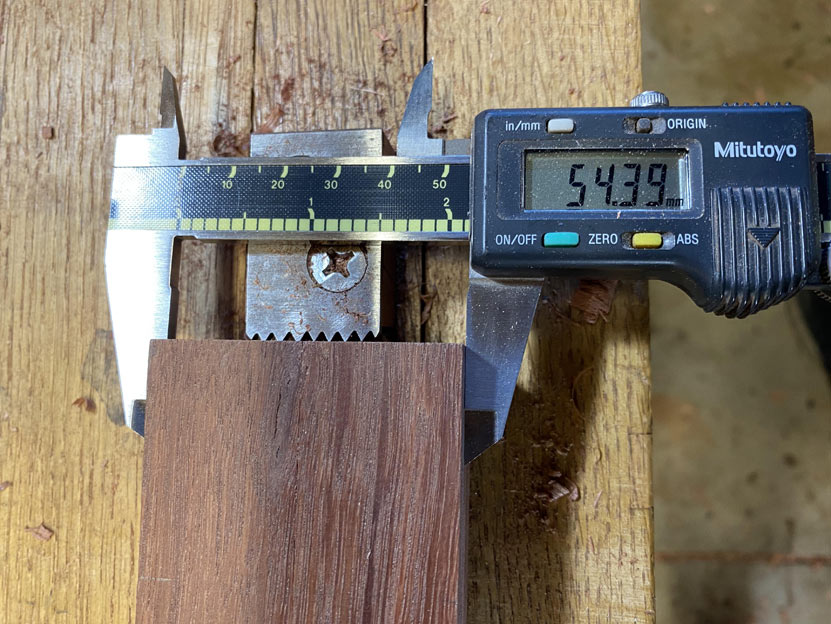
One end is 44.12mm ...

28a.jpg


... and the other is 46.46mm, which is a difference of 2.34mm.

27a.jpg


This will work - the pin socket is measured from this (in the same way as dovetails for a drawer.

The reason for the 7mm depth? The case is 20mm thick. the dovetail should be about 1/3 of this thickness. I decided to take it to the depth of the rebate for the rear panel ...

29a.jpg


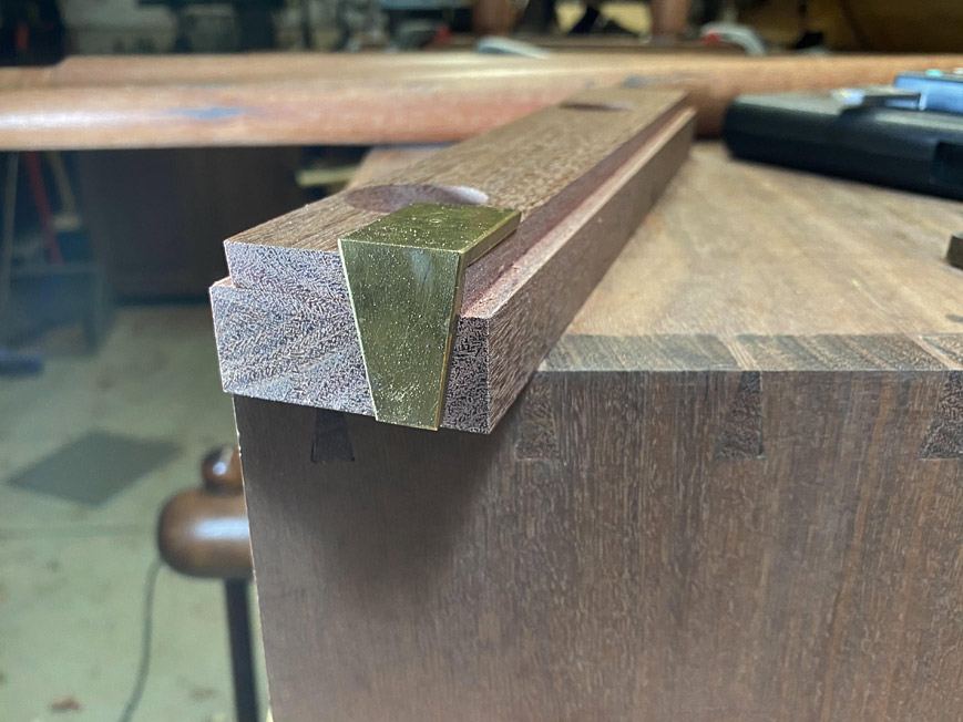
So, here is one of the completed bases ...

30a.jpg


And this is where it will be fitted ...

31a.jpg


Regards from Perth

Derek
 
Following hot on the heels of the last post, where we created the male or tail section of the tapered sliding dovetail, now comes the female or pin socket to house the base for the legs.

1a.jpg


These are the bases. This post will focus on the socket for the one closest the camera.

2a.jpg


The base is positioned exactly 3 1/4" from the side. The tapered side is on the inside, with the outside face square to the front and rear of the case ...

3a.jpg


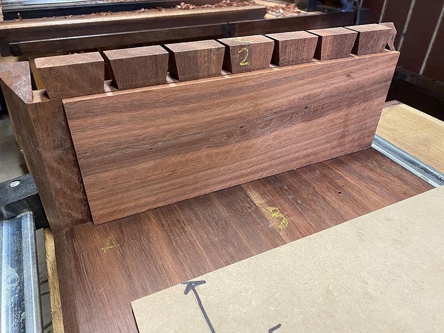
This process is essentially the same as transferring marks from the tail- to the pin board with drawers.

The base tapers towards the toe, that is, the sliding dovetail will tighten up as the base is pushed into the socket.

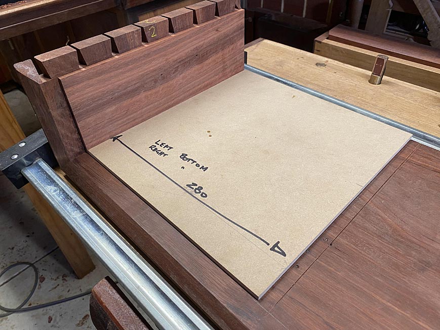
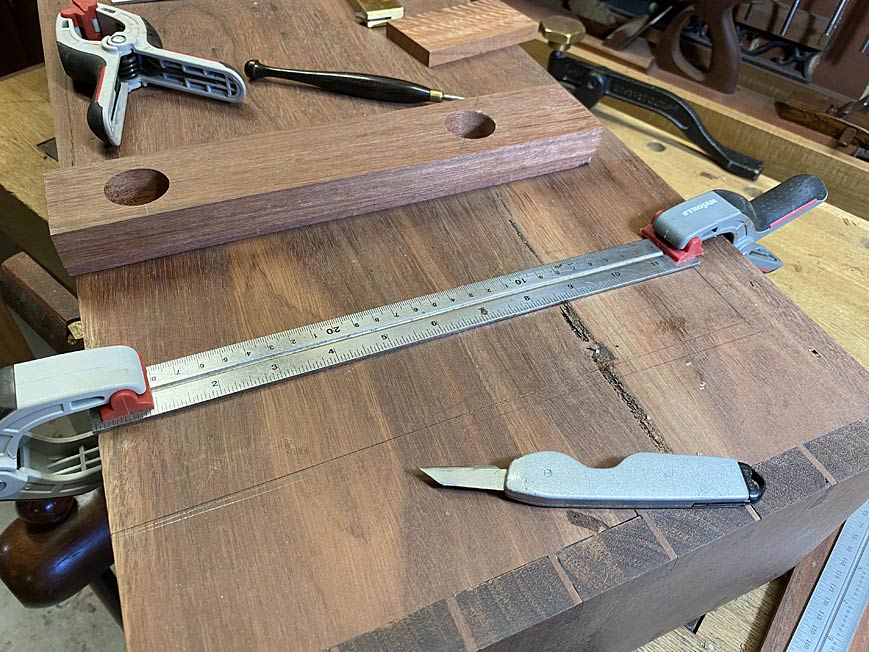
The first step is to register the far end of the base in such a way that the position is repeatable. This is done by placing a long board along the "square" side. The position for the end of the board is marked ...

4a.jpg


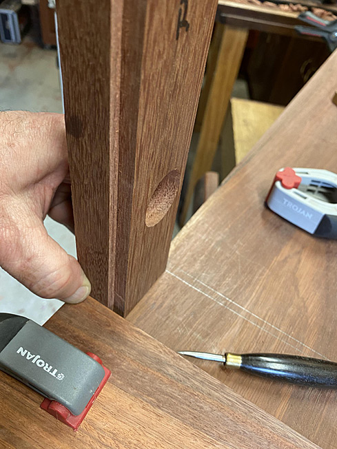
Now the base can be stood up to mark inside the tail with a scratch awl. You can make out the mark aligning the baseline of the tail ...

5a.jpg


Look carefully for the dots.

6a.jpg


This is repeated at the other end.

7a.jpg


The dots are now joined up ...

8a.jpg


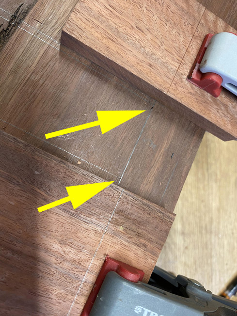
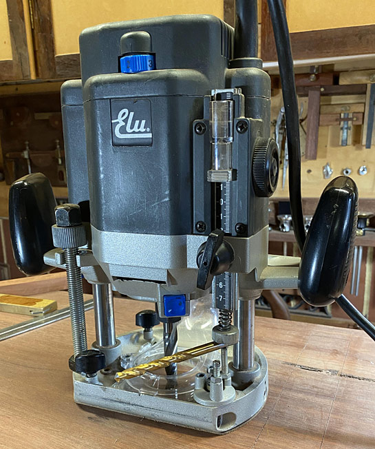
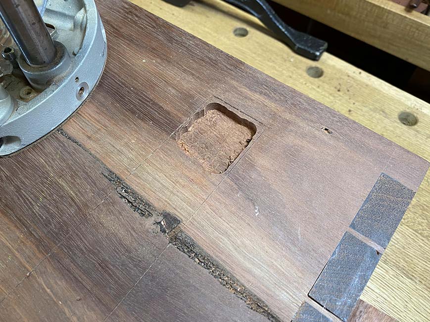
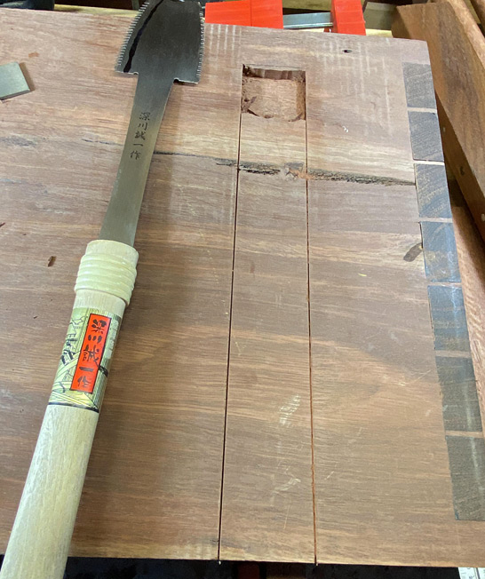
The plan is to saw the socket sides, as if sawing dovetails in a drawer. The angle ratio is 1:6, as it was with the base. Since the socket is blind or stopped, the saw needs to have space in which to begin the cut. An area at the toe is excavated with a router.

The depth of the cut is set using a 7.0mm drill bit. I am aware that the actual depth is 7.5mm, but this will be a second pass. I intend to clear the waste with the router - this Jarrah is bloody hard, and I am not a masochist! :)

9a.jpg


10a.jpg


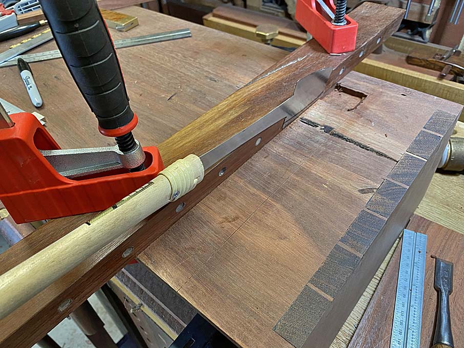
Using an angled saw guide, the end is chopped to the line ..

11a.jpg


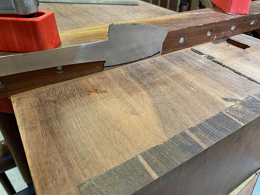
Now this is space to register the azebiki saw ...

12a.jpg


I have roughly marked a depth to aim for ...

13a.jpg


Both sides have been sawn ...

14a.jpg


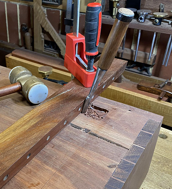
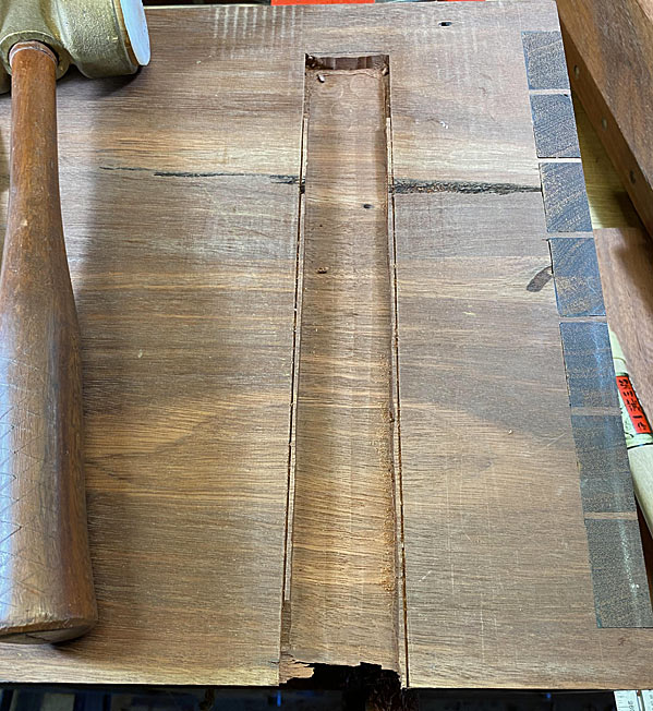
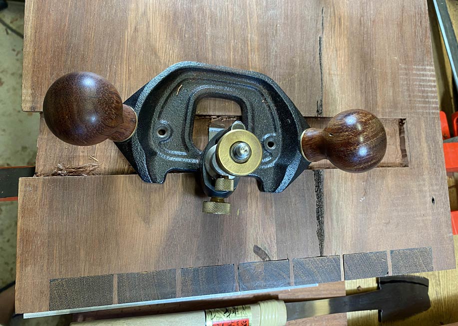
The waste is removed with the router, leaving a few mm close to the sides ...

15a.jpg


This is chopped away with a chisel in two passes, and then cleaned up with a hand router ...

16a.jpg


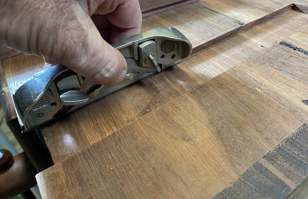
The side rebate #79/dovetail plane is used to clean any rough sections ..

17a.jpg


The power router drops a 0.5mm to 7.5mm and this is cleaned up ...

18a.jpg


Amazingly, the base slides in and tightens up about 1/4" from the end. It will need a tap to be fully secure.

19a.jpg


That's it for now.

Regards from Perth

Derek
 
Brilliant! I know it must take twice as long when you have to stop and take photos but not only do you achieve precision, you show the rest of us how to do so, in clearer detail than any other source.
 
Thanks for the build thread Derek. Interesting to say the least. I am curious though in that you were concerned bout crossgrain stresses with the dividers et cetera inside the case but the leg piece will be just that. Or do you have plans to pin/screw/glue the rear end and allow the forward end to float? Maybe I should wait for the next instalment. ;)

Pete
 
A tapered sliding dovetail is the classic way of dealing with movement. It was often used for big boarded doors, for instance, and for table tops. I'm assuming that Derek will just give it a good clout with a hammer and that will be that.
 
Inspector":2arpkjyp said:
Thanks for the build thread Derek. Interesting to say the least. I am curious though in that you were concerned bout crossgrain stresses with the dividers et cetera inside the case but the leg piece will be just that. Or do you have plans to pin/screw/glue the rear end and allow the forward end to float? Maybe I should wait for the next instalment. ;)

Pete

Pete, I am concerned with cross grain movement with the bases as well. This will be dealt with by only glueing them at the toe, and leaving about 3/4 of the base to be free to expand towards the rear (as you have anticipated).

Regards from Perth

Derek
 
Back
Top