dual extractor design + cyclone install

UKworkshop.co.uk

Help Support UKworkshop.co.uk:

This site may earn a commission from merchant affiliate links, including eBay, Amazon, and others.
gasmansteve":350uzhu6 said:
Steve
Hows it go with the black garden bin? mine just kept imploding if the inlet tube got a few too many shavings in and thats using a 1250watt vac :? .
When I get the time I`ll knock up a smallish mdf/ply bin just big enough to fit a black bag in.
Cheers
Steve

Steve, I can completely block the inlet, the cyclone contracts slightly, the garden bin is fine and the blowers start to "race".

no collapsing.

Steve
 
Tony Spear":okb3ghse said:
Steve, very interesting indeed.

A couple more questions:

I notice that most cyclones (icluding your big one) have the inlet and outlet ports fitted in a parallel sided section on top of the cone. Any particular reason why you didn't follow this practice?

not sure what to make of this, both my large and vac cyclone have the inlet on the side and the outlet from the top. I have seen designs where both the inlet and exhaust are on the top, but I didn't follow that route.

Tony Spear":okb3ghse said:
Your final dimensions are slightly different from the original proposal (10" high v. 12" and bottom dia 4" v. 3.5") any particular reason for this?
I'm interested in this because in several other places I've come across comments regarding the height v. diameter ratio (1.6 or 1.64) and your original 12" dia. (1.71) seems to be much closer to this than the final 10" dia. (1.43).

What do you mean by "inlet port enters the side 3.5" on centre"?

Has your bucket shown any signs of collapsing under the suction?

Providing that other members of this forum have left any out there :lol: , I think I might try this using a road cone either fitted into a plate like yours, or more likely I'll fit the cone in the top of a ply or mdf cabinet with a removeable bucket inside. I'd have the cabinet door hinged and sealed with draught excluder which would eliminate any leakage problems.

Any comments would be greatly appreciated.

PS; i need to find out about this air ramp business - I can't understand most of the descriptions I've read. Any idea where I can find a photo?

In pumping plants they use cyclones for 2 applications - bloody great big ones (I've seen them nearly 10ft high) for sand separation on the outlets from borehole pumps and tiny little ones to eliminate solids from gland sealing water. I've just looked at a sectional illustration of one of these little ones and the bottom of the outlet pipe seems to be immersed into a central cone within the main cone. Would this effectively be performing the same function as the air ramp?

Tony,

I based most of the design on a the dust deputy. Bit cheeky really, I downloaded an image, upscaled and printed it. Then used one known dimension to scale the entire design (I think it was the inlet port diameter). And went from there.

I was limited by the size of the bucket I used but
s far as possible I`ve tried to follow the dust deputy design, printing a picture from their website and based on the stated 2 inch inlet port, I derived the measurements:
approx 12 inches high, top diameter approx 7 inch, bottom diameter approx 3.5 inch
I did have to trim 2 inches off of the height because of the lack of materials I had at the time. I (like you) was skeptical about this mock up as I (like you) had read about the height/diameter ratio. But it seems to have little effect and the mock up works so well I don't really want to change it/replace it.

Dropping the height from 12 inches to 10 and keeping the top/bottom diameters constant would result in an increased "wall" angle. So I increased the lower diameter by 0.5 inches to try to reverse the effect. Could have done the trig to work out exactly the correction, but as a guestimate its probably close enough.


sorry for the gibberish:
"inlet port enters the side 3.5" on centre"?

means 3.5 inches from the top to the centre of the inlet port.... sorry

as for the technicals of why the inlet port enters from the side, and continues into the cyclone rather than stopping flush AND designing and installing and air ramp, see
http://billpentz.com/woodworking/Cyclon ... fm#AirRamp

just a quick note, my vac cyclone has NO air ramp, my largers one is going to get one.

Steve
 
kityuser":tlj0fzvt said:
Tony Spear":tlj0fzvt said:
Steve, very interesting indeed.

A couple more questions:

I notice that most cyclones (icluding your big one) have the inlet and outlet ports fitted in a parallel sided section on top of the cone. Any particular reason why you didn't follow this practice?

not sure what to make of this, both my large and vac cyclone have the inlet on the side and the outlet from the top. I have seen designs where both the inlet and exhaust are on the top, but I didn't follow that route.

Steve

Sorry, I may have badly expressed my question. What I was trying to establish is why your mini-cyclone doesn't have a straight section on top of the cone, whereas your large one (and most of the others I've seen) does.

kityuser":tlj0fzvt said:
sorry for the gibberish:
"inlet port enters the side 3.5" on centre"?

means 3.5 inches from the top to the centre of the inlet port.... sorry

Steve

Understood.


kityuser":tlj0fzvt said:
as for the technicals of why the inlet port enters from the side, and continues into the cyclone rather than stopping flush AND designing and installing and air ramp, see
http://billpentz.com/woodworking/Cyclon ... fm#AirRamp

Steve

I've looked at the Bill Pentz site, but after a few minutes my brain begins to hurt :? I'm only a simple mechanical engineer and some of the higher physics goes right over my head, but from my use of cyclone separators in pumping plants I do understand the general priciple (on gland water systems we used to use them in series).

From something DaveL wrote, I'm under the impression that the air ramp is effectively something like a single turn of a right hand screw thread, which would tend to start the rotation and direct the air flow downwards at the same time. Have I got this correct? If so, I assume that the start of air ramp is installed in line with the top of the inlet pipe.

I understand the need for the inlet to extend into the cyclone (mainly minimises turbulence), but do you still do this if you have an air ramp?
 
Tony Spear":16yn4623 said:
Sorry, I may have badly expressed my question. What I was trying to establish is why your mini-cyclone doesn't have a straight section on top of the cone, whereas your large one (and most of the others I've seen) does.

I see, yup inlet enters the cyclone on the angle rather than into a straight side. Not sure about the physics of this one, just followed the dust deputy design.


Tony Spear":16yn4623 said:
I've looked at the Bill Pentz site, but after a few minutes my brain begins to hurt :? I'm only a simple mechanical engineer and some of the higher physics goes right over my head, but from my use of cyclone separators in pumping plants I do understand the general priciple (on gland water systems we used to use them in series).

From something DaveL wrote, I'm under the impression that the air ramp is effectively something like a single turn of a right hand screw thread, which would tend to start the rotation and direct the air flow downwards at the same time. Have I got this correct? If so, I assume that the start of air ramp is installed in line with the top of the inlet pipe.

I understand the need for the inlet to extend into the cyclone (mainly minimises turbulence), but do you still do this if you have an air ramp?

got it in one, and as for whether you need an air ramp AND extend the inlet into the cyclone, not sure, can't see that extending it inside (as I've done) will do any harm.
I have read, and seen on some american designs that the inlet is sometimes angled down a few degrees, i.e. does not enter the cyclone wall perpendicular to the side. I expect this is the same sort of thing as an air ramp, i.e. to direct the air/dust flow down into the cyclone rather than rotating around the top.

steve
 
Tony Spear":21a4bzz3 said:
From something DaveL wrote, I'm under the impression that the air ramp is effectively something like a single turn of a right hand screw thread, which would tend to start the rotation and direct the air flow downwards at the same time. Have I got this correct? If so, I assume that the start of air ramp is installed in line with the top of the inlet pipe.
Tony,

The air ramp is to help stop turbulence, caused buy the air coming in hitting the air that is already spinning inside the unit. The air does not have to rotate clockwise, if the position for your cyclone in the shop would suit the inlet coming in the other side that is not a problem, let the air rotate anticlockwise it will work just as well.
 
DaveL":70epe5n3 said:
Tony Spear":70epe5n3 said:
From something DaveL wrote, I'm under the impression that the air ramp is effectively something like a single turn of a right hand screw thread, which would tend to start the rotation and direct the air flow downwards at the same time. Have I got this correct? If so, I assume that the start of air ramp is installed in line with the top of the inlet pipe.
Tony,

The air ramp is to help stop turbulence, caused buy the air coming in hitting the air that is already spinning inside the unit. The air does not have to rotate clockwise, if the position for your cyclone in the shop would suit the inlet coming in the other side that is not a problem, let the air rotate anticlockwise it will work just as well.

doesn't that depend on whether you are in the northern or southern hemisphere?
:roll: :wink:

steve
 
kityuser":r90i6ot6 said:
doesn't that depend on whether you are in the northern or southern hemisphere?
:roll: :wink:

steve
I bet you have tried the talcum power on the bath water. :-k :whistle: [-( :wink:
 
DaveL":12nh2gk2 said:
Tony,

The air ramp is to help stop turbulence, caused buy the air coming in hitting the air that is already spinning inside the unit. The air does not have to rotate clockwise, if the position for your cyclone in the shop would suit the inlet coming in the other side that is not a problem, let the air rotate anticlockwise it will work just as well.

I understand that Dave, I only used right hand thread as an example as both of Steve's have the inlet on the left.
 
Looks a cracking setup, methinks I'm gonna have to have a bash at one of my own :D . I can only dream of enough spare cash to invest in a chunky blower though :cry:

One thing which did cross my mind...... could a leaf blower, with the ability to suck, make a reasonable alternative :?: Based on some quick googling you can pick up a 2500W jobbie for around 60 notes, in theory 2500W ~ 3.3HP! ....I can't think of any reason why it shouldn't :lol: .....
 
SteveJ":8tuzq0gh said:
One thing which did cross my mind...... could a leaf blower, with the ability to suck, make a reasonable alternative :?: Based on some quick googling you can pick up a 2500W jobbie for around 60 notes, in theory 2500W ~ 3.3HP! ....I can't think of any reason why it shouldn't :lol: .....
The main difference is the type of motor. Blowers like Steve (kityuser) has are induction motors, quiet in use while most leaf blowers are universal and much louder.
 
Sad news for Mrs KU today..... she lost her paper recycling bin side :?
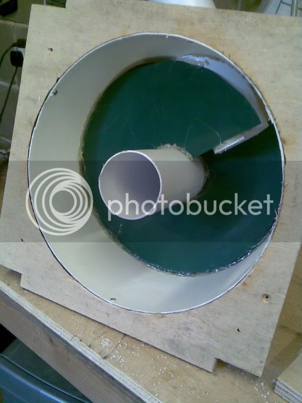
good news for me, I gained an air ramp! 8)

Image078.jpg


Steve
 
When I realised that I was looking at it from below :roll: , it's exactly as I'd envisaged.

I now can't make up my mind whether to make a mini-cyclone very much like yours or to try and make one incorporating everything I've learned over the last few days! :?

edited to correct typo's!

and add a question: How old is that 4 legged muck magnet you've got there? The only dog that can go out in the middle of a drought and still come home soaked and filthy! :shock:
 
Tony Spear":twh3va95 said:
I now can't make up my mind whether to make a mini-cyclone very much like yours or to try and make one incorporating everything I've learned over the last few days! :?

why not make both, like me :lol:
I suppose really it comes down to horses for courses. The large cyclone driven by the HVLP blowers really doesn't like being restricted in pipe diameter much below the 63mm I'm running it at (and I'm well aware that there is opinion out there that 100mm is the minimum), I know, I`ve tried. So power tools are probably going to be out of the question with the exception of my router table.
Where as the HPLV mini cyclone+shop vac is built for the small tools.....

at present I`m planning on
large cyclone:
1) startrite 351E bandsaw
2) kitty 419 tablesaw
3) thicknesser planner
4) router table
5) extraction hood for drill press

mini cyclone:
1) hand held routers
2) sanding down-draft table
3) general workshop cleaning


The main aim through the whole of this lengthy process is to achieve something on a budget. I was lucky enough to have a load of 63mm pipe and fittings. And I already had a charnwood extractor when another axminster one "came up" locally.
A few performance comprimises, but so far I`m chuffed with how things are panning out on the large cyclone.

Tony Spear":twh3va95 said:
and add a question: How old is that 4 legged muck magnet you've got there? The only dog that can go out in the middle of a drought and still come home soaked and filthy! :shock:
The 4 legged helper is "fosters" and he is coming up to 4 this year. My bestest mate in the whole world!

:wink:

Steve
 
spent a little more time last night.

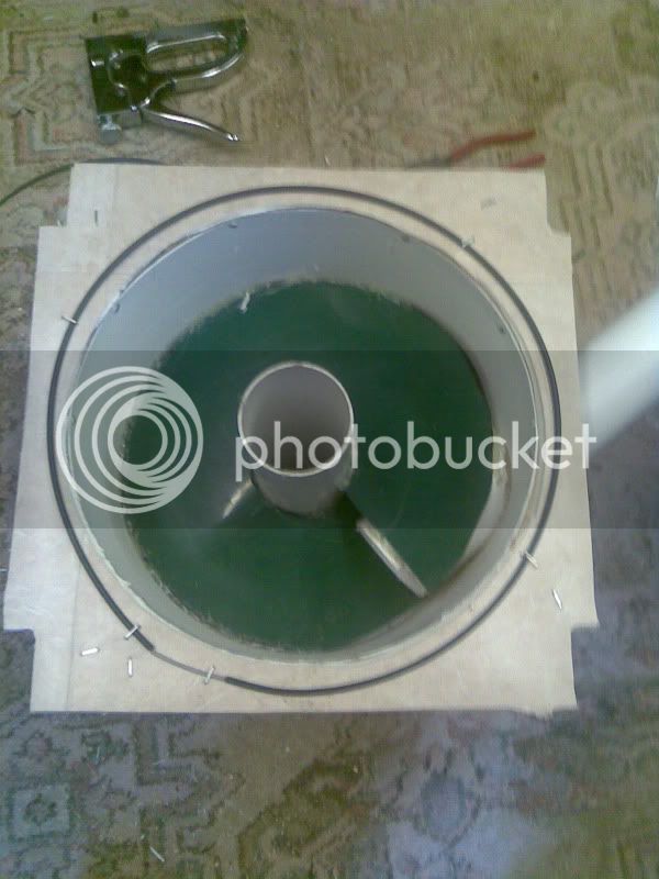
Image079.jpg


I`ve now applied a lino gasket and a "completely over the top" trick employed by race engine builders. The wire ring is to localise pressure around the cyclone bore hopefully making a better seal.
Common place in race built turbo`ed engines as it makes the head gasket tolerate a little higher pressure aka more boost.

I had the wire hanging around... why not :wink:

All bolted back together now (sorry no pics the phone ran out), sealed with mastic where needed and ready to connect back up again.

Steve
 
Warning This is starting to get Anal and a bit of an obsession

OK so I braved the HOT workshop tonight to start fault finding my air leaks on my extractor/cyclone system.

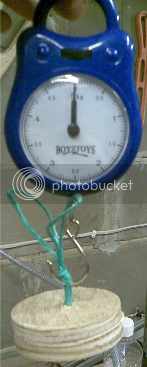
Got this off of the bay for a few quid :

Image084.jpg


The plug is cut a few mm narrower than the 63mm pipe:

Image085.jpg


on with the measurements!

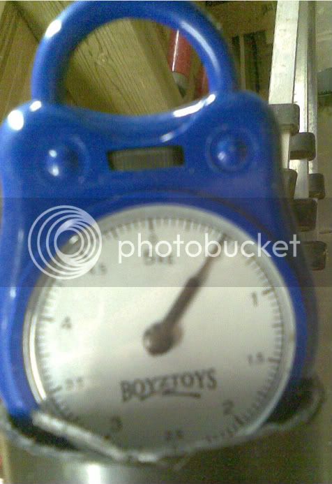
first up one blower, no cyclone:
Image081.jpg


Hopefully you'll just be able to make out 0.25kg

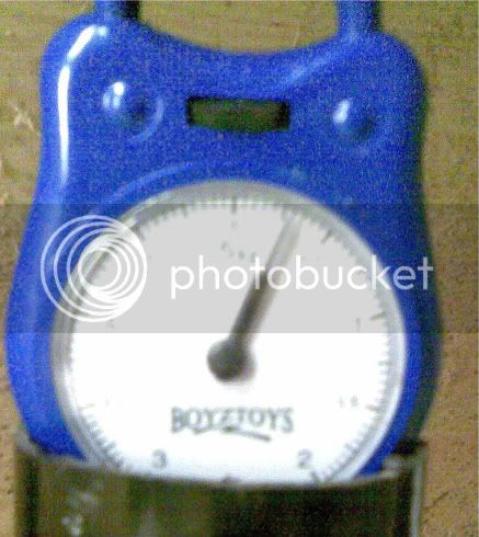
next with both blowers on, no cyclone:
Image082.jpg

by my reconning just above 0.5kg, thats double the suck 8)

now by this point its starting to get hot in the workshop and sweat is pouring off (literally).

But I connect the cyclone and start listening for leaks.
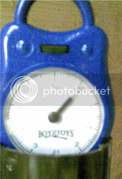
Lots of duct tape later (as a temp fix) I end up with:
Image083.jpg

close, but no biscuit yet :?
Sealing required around:
1) bin lid
2) bin lid -> flexi pipe
3) flexi pipe -> cyclone bottom

and guess what, I now have a partially collapsing bin :twisted: looks like I'll have to "rib" it.

I gave up under the heat stress 8)

looking promising, I need to mount the cyclone properly but don't yet have the funds to spray and clean it up.
but I REALLY want to plastic weld all the piping and hook it up :roll:
I recon I must be still loosing 5-10%...........

Steve
 
after securing the funds I`ve finally taken delivery of
http://cgi.ebay.co.uk/76mm-PU-FLEXIBLE- ... tsupported

which is a dam sight cheaper than:
http://www.axminster.co.uk/product.asp? ... =1&jump=44
200774 Clear Extraction Hose - 75mm x 2.5m £26.65

even if I did try a sneaky and phone the shop directly (as the website stated free delivery) but they weren't having any of it, bit harsh seen as how they would have saved on the ebay and paypal fees.

anyhow, looking forward to getting home tonight to try out my new system 8)


Steve
 
kityuser":13ssfwbu said:
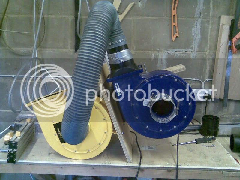
Image067.jpg


This was the second attempt today. I`ve fired both of them up and the good news is there is a HUGE increase in suck when the second yellow extractor is powered.... a good start.

I connected up my current meter in line and started to test the system.

I measured the following:

blue | yellow
-------------------
on.....|.....off
2.16A |.....x
-------------------
on.....|.....on
2.19A |.....x
-------------------
off......|.....on
x........| 2.90A
-------------------
on......|.....on
x........| 2.94A

Both extractors on give me a current draw of 4.92A with no appreciable difference in tone or volume from each with the other on or off.

when I stick my 100mm to 63mm reducer on the 4.92A reduces to 4.76A with a slight increase in tone from each. I presume they are being starved slightly. However the suction from the end of a 2 meter length of 63mm drain downpipe is immense :twisted:

I know that reducing the bore is not going to be the most clever of things, but I`ve got an abundance of fittings and piping for wickes 63mm downpiping.....

Steve

Could this theory be put into practice with an existing extraction system to boost airflow? How would it work connecting to a axminster wv extractor? one being hvlp the other hplv?
Cheers
Rob
 
Rob,

The 2 extractors as pictured are both chip extractors and thus hvlp, I have no idea if you could mix a hvlp and hplv system, I expect not.
Certainly if the hvlp extractor was added to the exhaust of a hplv extractor all that would happen would be that the hvlp would be starved of air........


steve
 
Steve,

Inquiring minds want to know:

Are you still alive or did your inline DCs burn down your house?
Did it all work out or have you scrapped it all and moved on to your next ingenious idea?
Do you have any additional words of wisdom about it 8 years later?

I'm hopeful to hear "yes," "it did," and "not really, just do what I did and you'll have the snake oil."

Best,

Reed
 
Back
Top