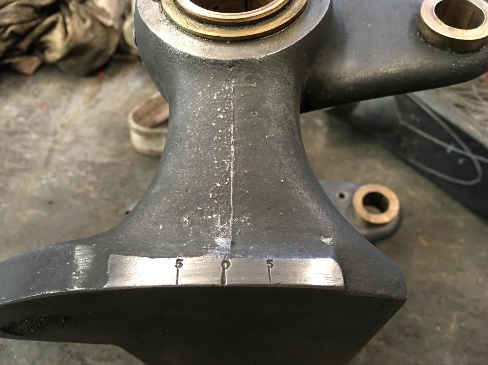
Drummond B lathe

UKworkshop.co.uk

Help Support UKworkshop.co.uk:

This site may earn a commission from merchant affiliate links, including eBay, Amazon, and others.

wallace

Established Member
Joined
13 Feb 2011
Messages
2,130
Reaction score
274
Location
county durham
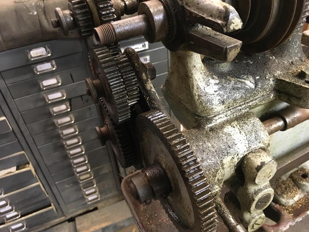
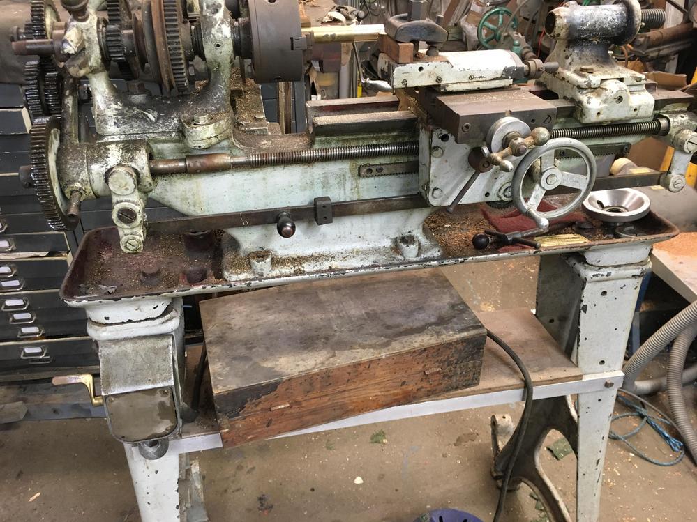
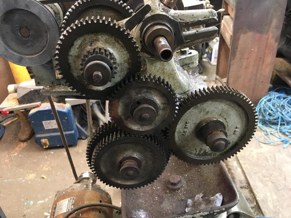
I recently aquired a rough little B lathe. I'm struggling with the change wheels. The old guy that had it said he had never used it for screw cutting. I dont know how the wheels should be arranged to provide a slow motion when the feed is actuated. When I press the feed lever it goes to the right.
I had a look on the drummond group which is a horrible place to navigate.
8EGHbga.jpg


rQGaPHP.jpg


vzNcgCZ.jpg
 
Do you have a box of spare cogs and gears that came with it?

Are you able to turn it by hand and drive the cogs and gears - I only ask because assembling a gear chain and firing up the mains motor is going to be a risky process if you have it wrong.
 
I have a different type of Drummond and it is a treadle drive. I will try an photograph the gears set up later and the sizes of the additional gears that came with it.
 
I got some advice from the guys on the drummond group. Apparently the previous owner was a mad man or genious.
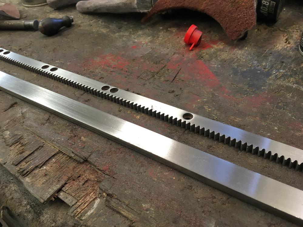
He has the drive coming off the back gear and has modified the apron to give handwheel feed via an added on rack and a solid nut instead of a split nut
 
Wallace,

There is a basic methodology for selecting drive gears. I have an old Boley with no instruction manual. Here is the spreadsheet I constructed to select the ratios for any feed (PDF copy sorry as spreadsheet files aren't accepted). If you have a 127 tooth gear you can cut either Imperial or Metric pitches with no compromise (if you don't, you can't). The example here is for an Imperial leadscrew for which you put the 127 gear as a DRIVEN gear, preferably the last in the chain, in order to get metric threads from an Imperial leadscrew.

The first thing you need is the leadscrew pitch. Just measure it, probably a threads-per-inch pitch for a Drummond. Then list the number of teeth in the gears that you actually have in your pile.

The next is the first two gears in the train. Since you mention that the drive is off the back gear, you will have an extra two gears on the left of the spreadsheet, which will be the back gear ratio, something like 1:4 (the numbers don't matter, could be 25 and 100 for example.
Then you add the gears in the order in which they engage, the first one of each pair being the DRIVING gear the second the DRIVEN gear.

The ratio column is optional, just might help in fiddling around to get ratios.

After the back gear, there will be a driving gear (1 in my table) which must mesh with the next driven gear (2). The latter is on a shaft that cn slide along the banjo. The banjo can also rotate to bring the two gears into mesh. Then there will be another gear on the same shaft as gear 2, which will be gear 3, the next driven gear. This in turn can be made to mesh with gear 4, the final driven gear. There is always a banjo that can be rotated, or a slide to translate the shaft, so that the gears can be made to mesh.

The final column will be the thread pitch (mm in the metric table, TPI in the Imperial). This is exactly the same as the the feed pitch when turning a cylinder.

That's it. There's no great magic in selecting the gear pairs and often there are several combinations that will work. In general choose the combo that has fewer teeth on the driving gear and more teeth on the driven gear where possible. Some combinations might be excluded because of other bits of the lather or the shielding getting in the way.

PM me your address if you'd like a copy of the spreadsheet in xlsx format. If you aren't comfortable with spreadsheets, if you send me all the numbers of teeth on the gears you have, the leadscrew pitch and the back gear ratio I'll be happy to construct the table for you.

Keith
 

Attachments

  • boley gears.pdf
    38.2 KB
Keith thanks very much for all of that, I think it will be a while before I've reached the level to be doing threads. The lathe seems to be set up to cut a left hand thread. The tail stock quill is rusted solid so it needs some tlc
 
Wallace
there a couple of soft back books regarding setting and using metal lathes....
I canot rememeber the auther but he also did books on screwcutting , milling etc.....mine are packed somewhere....
they were excellant for ref.....
as said go to modelengineer forum...very good for everything metal...also ask about the books, someone will know....
happy days with ur lathe....
 
I have a different type of Drummond and it is a treadle drive. I will try an photograph the gears set up later and the sizes of the additional gears that came with it.
Just out of interest, SM, is that the round bed Drummond? I ask because as a small child my father had such that was treadle driven. My brother now has that machine. I remember using it in my teens to turn Meccano parts, but by then my father had changed it to a motor drive.
 
Hi I saw this on the Drummond lathes page which is probably best place as there’s lots of these machines about. The ingenuity of former owners is a story always to be investigated.
There’s a book by Sparey which can be picked up on. E bay which runs through all of the basics as well as showing how capable they can still be. If you haven’t got the full set of gears 3 d printing is the way to go as it gives quieter running gears for reasonable outlay.
 
Just out of interest, SM, is that the round bed Drummond? I ask because as a small child my father had such that was treadle driven. My brother now has that machine. I remember using it in my teens to turn Meccano parts, but by then my father had changed it to a motor drive.

Sorry - this one has a flat bed.
 
Keith thanks very much for all of that, I think it will be a while before I've reached the level to be doing threads. The lathe seems to be set up to cut a left hand thread. The tail stock quill is rusted solid so it needs some tlc

There should be a reversing lever in the gear train that will select forward/neutral/reverse. It may the the plunger at the bottom left of the first picture.
For right hand threads (or slow feeds from right to left) the tool moves from right to left (towards the headstock) when the drive is engaged. The engaging lever looks like the one on the left hand side of the carriage. It's usually a little better to feed towards the headstock when simply cutting, as it's a better direction for the bearing loading.
 
There is a reversing leaver for the B but I dont have it, by all accounts its a rocky horse item.

A bit of aluminium bodge to level things up a bit

IMphqEw.jpg


k027j0y.jpg


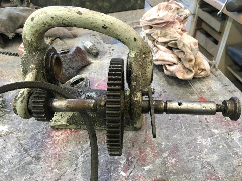
The head stock and back gear shaft

AWlzUAa.jpg


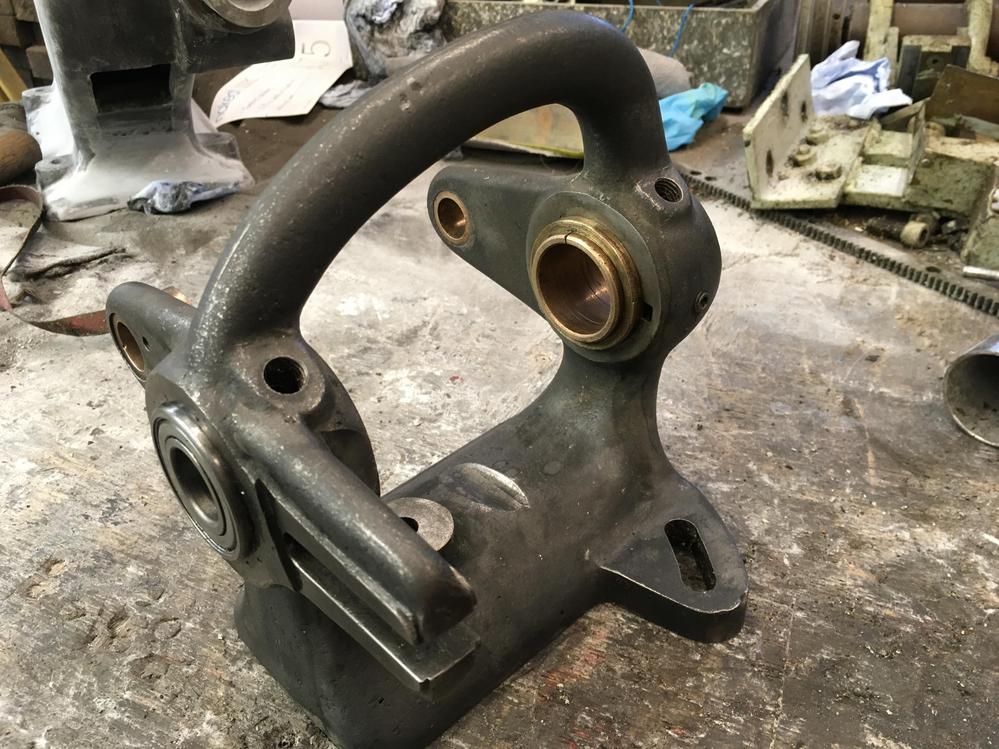
One thing that has really impressed me is the quality of the castings, straight out of mould with no fettling

2F2Q6IM.jpg


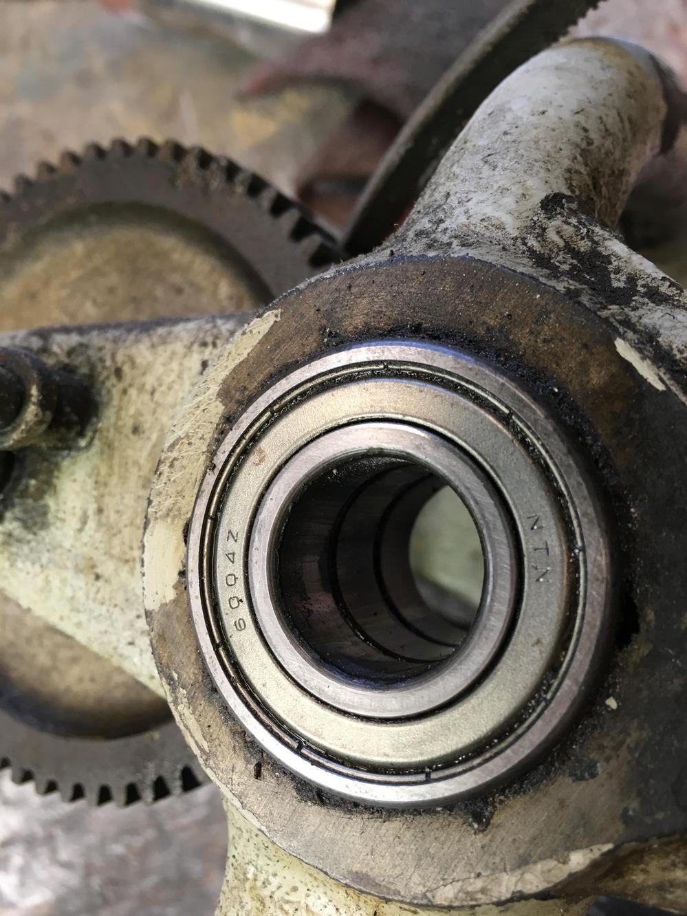
A previous owner has put a row of 3 sealed bearings in one side of the head stock, they are japanese so might be good quality

FjUMcfU.jpg


One thing I'm undecided is what colour to do this. Should I stay original and paint it black or my usual grey with red innards. I should I get a bit crazy, I've always liked the colour of coronet lathes.
I always had an itch to line a machine, like what was done on big stationary engines like crosleys.
 
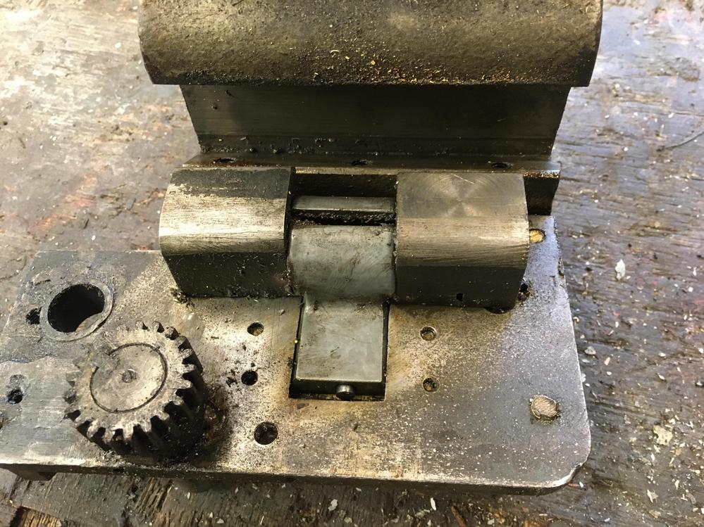
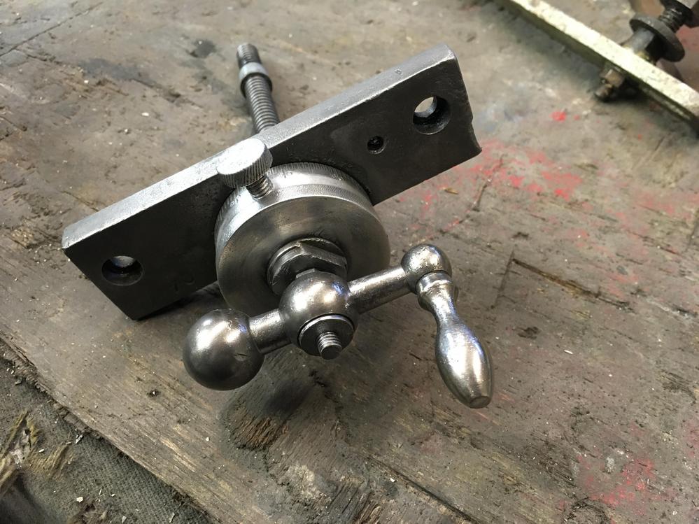
This is the back of the apron, I dont have a clue what its supposed to look like but theirs been some tinkering

MNVOMnW.jpg


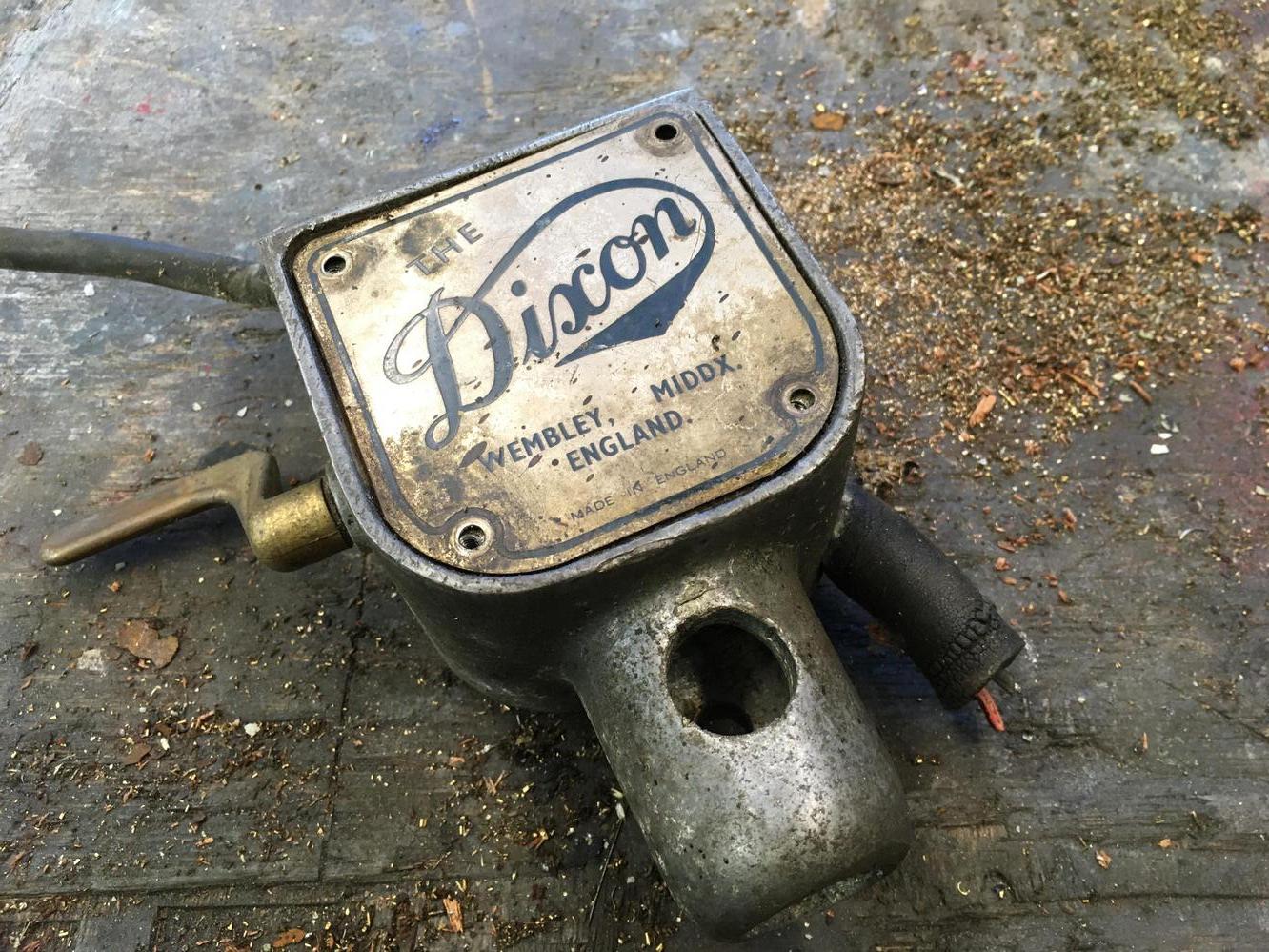
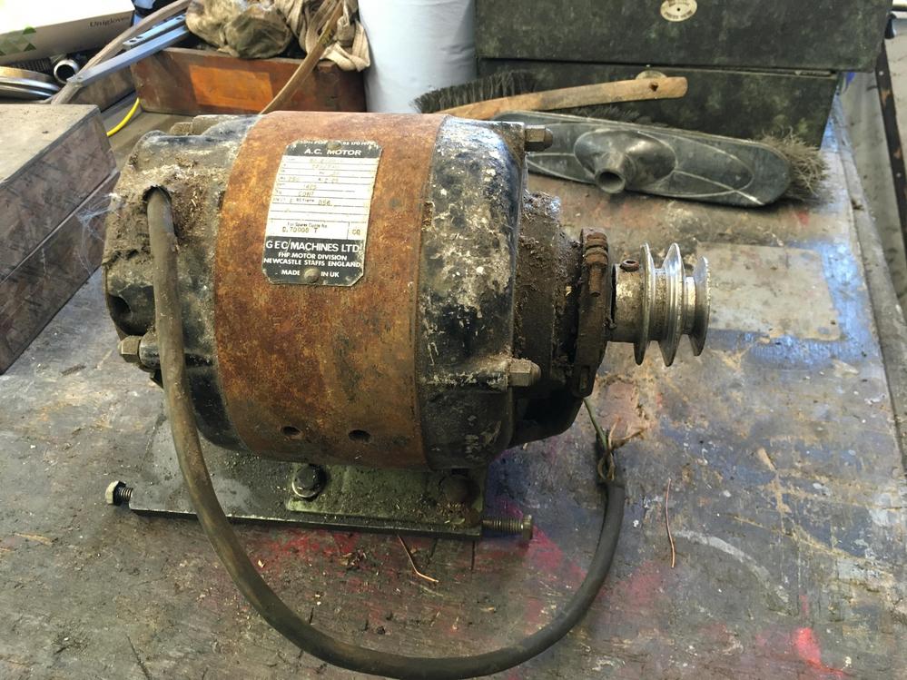
I took the motor and switch off, its quite a nice thing. I have a nice little 3 phase brooks motor that will be perfect for this. I'm going to rig it up through a vfd

xeOzCMq.jpg


DLiu48v.jpg


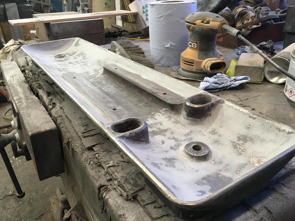
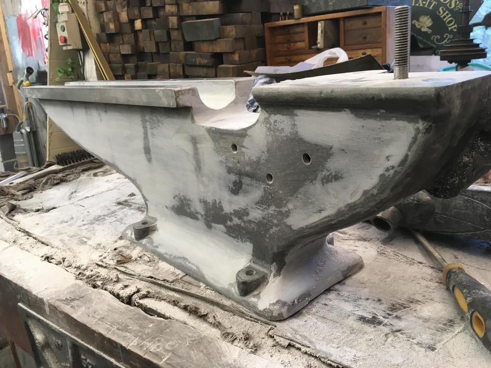
Did a bit aluminium filler

DSj49WN.jpg


And made some bits nice and clean

2juwxCS.jpg


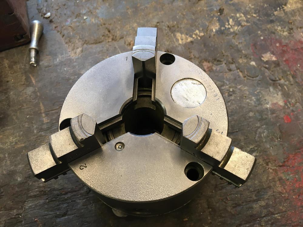
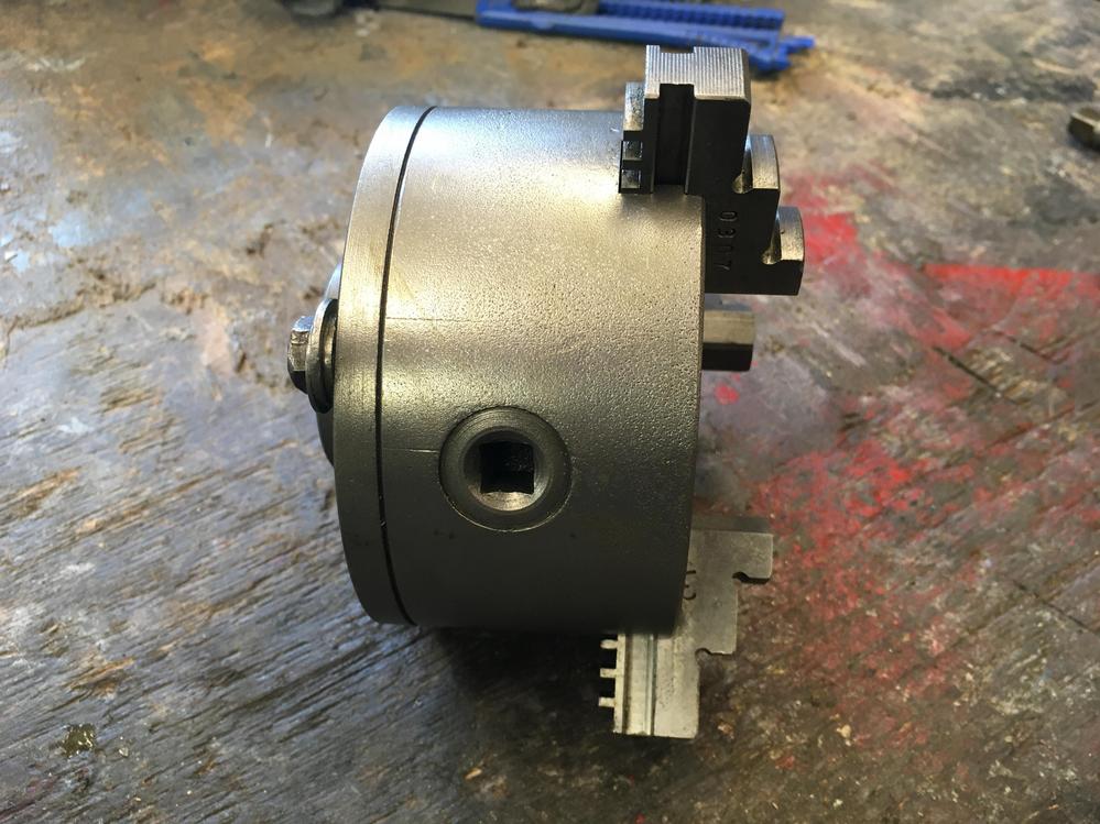
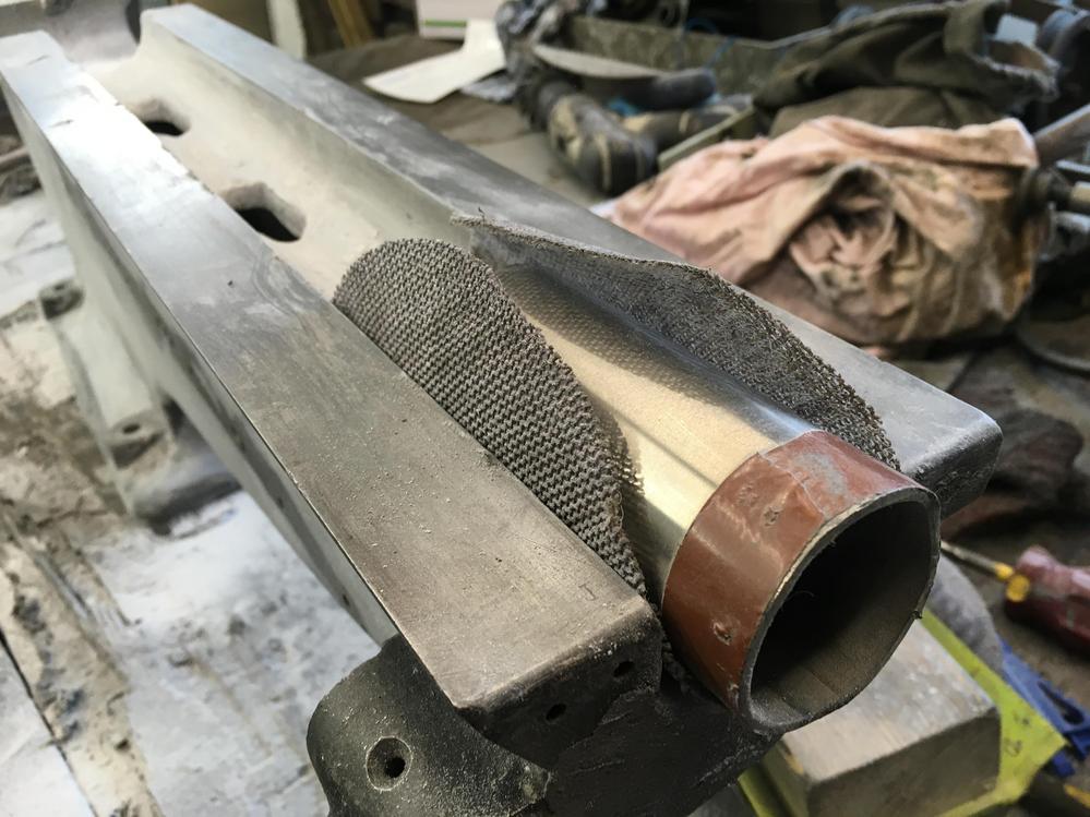
I stuck the chuck in some evaporust and then wire wheeled it

zgwMtvY.jpg


yd6OQmR.jpg


For the life of me I couldnt get the lead screw to bits, I thought it would either unscrew or just slip off. But I could not get it to move. It spins freely

o0vYvMX.jpg


Why would a head stock need to moved out of line

pT5Gy9Z.jpg


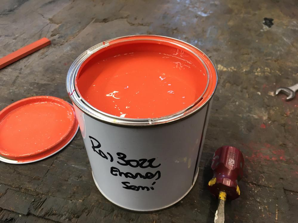
I ordered some paint and I think there must of been a failure to communicate, I asked for RAL 3O32 which is a dark ruby red, but what I got was 3O22 which is salmon pink

XKLwPbW.jpg

Pink it is then! Colour decided.
 
Oh I get it, if you werent turning between centres. Wouldnt it be easier to do it with the cross slide
 
Back
Top