Clock WIP - Maintenance

UKworkshop.co.uk

Help Support UKworkshop.co.uk:

This site may earn a commission from merchant affiliate links, including eBay, Amazon, and others.

Yojevol

Clocking on
Joined
29 Jan 2017
Messages
1,901
Reaction score
1,330
Location
Wotton-under-Edge, Glos
It was back in April that MikeG posed the question 'Has anybody made a wooden clock?' and I was able to report that I had started one. The project lay dormant until a couple of weeks ago when I dusted it off and started to make the frame.
The gears and pinions were made in the initial spurt of enthusiasm. This is what they look like:-
cl4.jpg

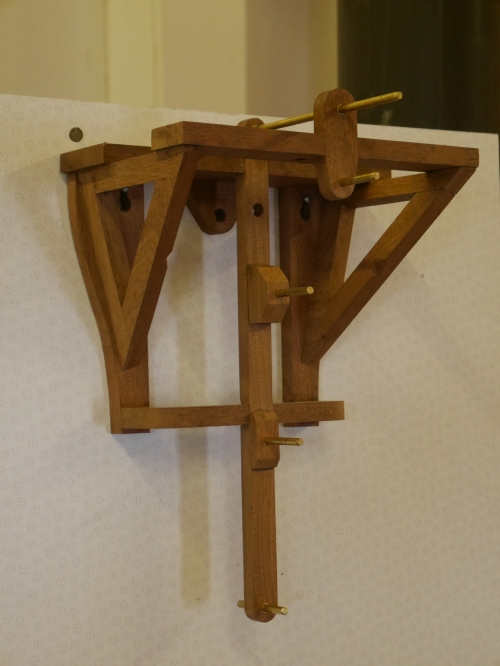
The frame has been made out of mahogany from an old office desk drawer. Here it is complete with its brass shafts in place:-
cl1.jpg
It departs slightly from Clayton Boywer's original design in that the central vertical support (with the 3 shafts) is tied back to the wall plates to give added rigidity.
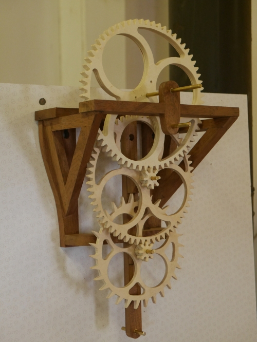
Having got the frame made I could then mount the main gear train and give them a twirl:-
cl2.jpg
Amazingly the all ran together nicely. I had previously run individual gear/pinion combinations on a lash up frame so I was reasonably confident of a good result.
The second train of the 2 smaller gears provides motion to the hour hand. These are proving a bit more problematic. They're binding up frequently, so I'll leave that aspect to the next report.
Brian
 

Attachments

  • cl4.jpg
    cl4.jpg
    250.9 KB
  • cl1.jpg
    cl1.jpg
    220.5 KB
  • cl2.jpg
    cl2.jpg
    241 KB
Clocking on again.
A bit of fettling with the dremel got the hour train moving smoothly:-
cl3.jpg
The next stage is to add the weight winding pulley. I can then get any idea of the amount of lead required to drive the clock.
Brian
 

Attachments

  • cl3.jpg
    cl3.jpg
    237.6 KB
Is that a trial and error process?
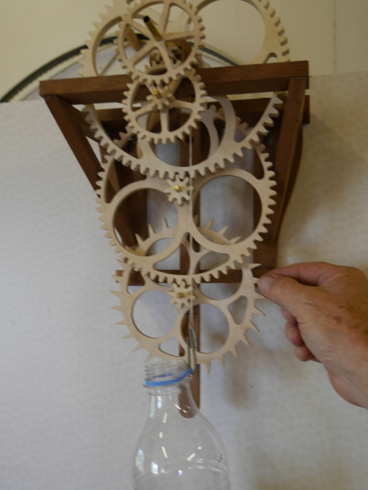
Not really, Mike. The idea is to hang a bottle on the winder drum and then add water until it starts to move. I may have to polish the brass shafts if stiction is significant
 
Weighting time is here!
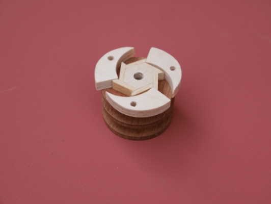
The next stage is to get the weight winding drum made. This is a complex little assembly which has a ratchet system that enables easy rewinding once the weight falls to its lowest. Here are some pics:-
cl7.jpg
cl6.jpg
cl5.jpg
.
So with this assembly mounted on the shaft and a short length of cord wound on, I could then hang a water bottle on to get the system moving with a bit gravitational assistance:-
cl8.jpg
Initially I let the weight fall freely and everything seemed to run smoothly. However, when I slowed it down to a more realistic stop/start motion stiction started to be a problem. It soon became evident that just half a dozen teeth on the Intermediate Gear needed a bit of fettling. By close of play yesterday I was happy that it basically worked.

The required weight needs to be about 600gm. The drum circumference is about 100mm. The drum has the capacity of 30 turns of cord giving a maximum run for 30 hours. That means the weight has got to drop by 3m - not practical in most situations. However the drop can be halved by adding a single pulley block. The weight is hung from the pulley and the other end of the cord is anchored up on the clock frame. This gets the drop to a more manageable 1.5m. The downside is that the weight needs to doubled to achieve the required torque on the drum. Also the pulley will add a bit of extra friction. So it looks as though the weight is going to be in the region of 1.5kg.

Next stage is to make the pendulum and escape mechanism.

Brian
 

Attachments

  • cl7.jpg
    cl7.jpg
    227.4 KB
  • cl6.jpg
    cl6.jpg
    120.2 KB
  • cl5.jpg
    cl5.jpg
    206.4 KB
  • cl8.jpg
    cl8.jpg
    429.8 KB
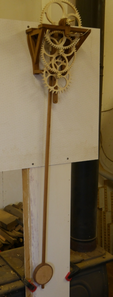
We're in the swing of it now - the pendulum is complete and swinging nicely:-
cl93.jpg
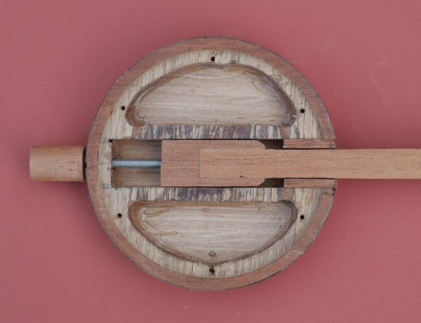
The bob weight was quite an intricate thing to make. Here it is with its rear cover removed:-
cl9.jpg
The screwed slider allows the effective length of the pendulum to be adjusted so that its natural swing frequency can be set at 2secs.
Here it is with the the voids filled with lead shot:-
cl91.jpg
This is the hanger/pivot at the top end:-
cl92.jpg
An initial play with it indicates that it's about 2secs per minute slow and that's with the adjustment at its shortest, therefore fastest, position. I'll leave it at that for now and see what its like when connected up to the escape mechanism.

Brian
 

Attachments

  • cl93.jpg
    cl93.jpg
    225.3 KB
  • cl9.jpg
    cl9.jpg
    202.1 KB
  • cl91.jpg
    cl91.jpg
    213.5 KB
  • cl92.jpg
    cl92.jpg
    201.2 KB
https://m.youtube.com/watch?v=c3sOuEv0E2I
I should save that sort of praise until you see the end result - it may be firewood! Anyway my hair is a rather lighter shade of black than that. Perhaps I should start dying it - I think I've got an old can of ebony in the workshop.
Brian
 
The weighting is nearly over. Completed the weights and their pulleys today:-
cl94.jpg


I pondered over what material to use for the weight cylinders. A choice of aluminium or stainless steel tube which I have some scraps of but neither were quite right so I decided to stay true to the wooden format and use wood. I had the remains of a mahogany cabinet door full of holes and mortices so not much use for anything else. I machined up 24 staves with 15° sides and glued them up to form 2 12 sided tubes. Made some end caps and turned them into cylinders on the lathe. Each has a capacity to hold almost 1.5Kg of lead shot, although only one will be filled to power the clock. The other is left empty but will be used to wind the weighted one up once a day. Hope to get it working with the new weights next week.
I've been playing with pendulum length adjustment in recent days and have managed to get accurate to within 2secs/hour.
Brian
 
Last edited:
It's taken a bit longer to move on since my last post. Two steps forward, one step backwards. The step backward was a Gerard Hoffnung moment when, in a lapse of concentration, I let go of the rope and the barrel proceeded downwards and, on hitting the floor burst asunder, allowing the lead shot to escape. Fortunately, through my natural untidiness, the floor dust and shavings prevented it spreading too far!
However, it did make me have a rethink on the use of lead shot. I decided to go back to solid lead. I made a rudimentary cylindrical mould out of ali tube and cast 2kg of scrap flashing lead. The result was a bit rough and ready so I turned it down so that it fitted nicely in the remaining mahogany tube. Here it is under test:-
cl97.jpg
With the damaged cylinder now repaired and demoted to the role of Dummy Weight, I have been able to get the clock running pretty reliably. Its running fast by about 2mins/day but I haven't attempted to use the pendulum fine adjustment yet. You can see it running here

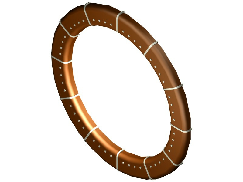
Meanwhile I have also started making the face ring. The intention is to make this design:-
CAD Face.jpg
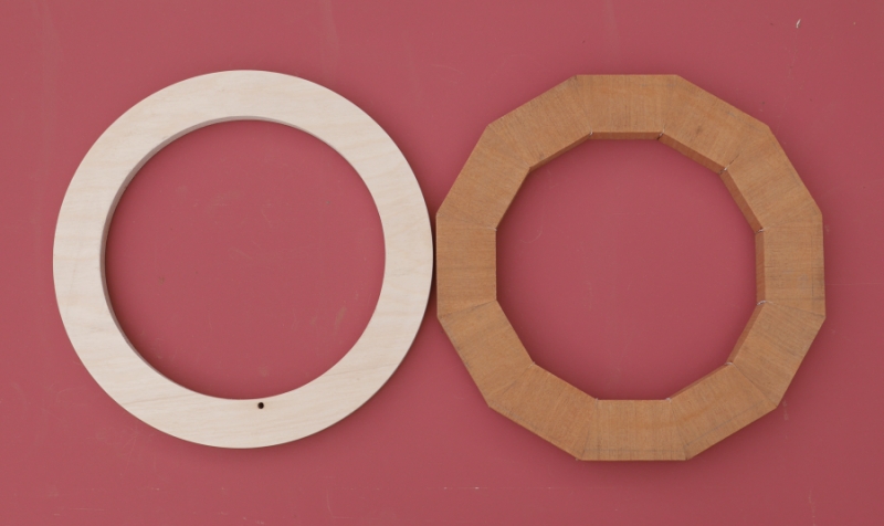
The big challenge here are the hour markers which are larger than the basic ring. To start with I made a 12agon ring out of mahogany blocks and turned a plywood ring pattern to the final size:-
cl96.jpg
After gluing the two together, I shaped it to the pattern on the spindle moulder and the machined round-overs using a router cutter (on the SM).
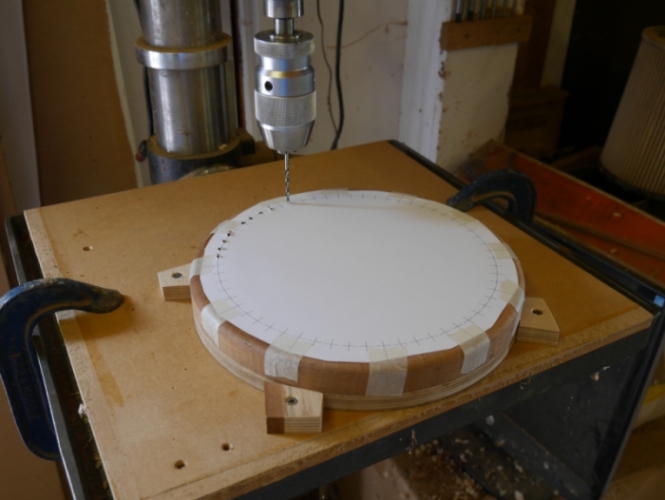
I then rigged up a jig on the pillar drill to drill holes for the minute indicator spots using a CAD printed pattern:-
cl99.jpg
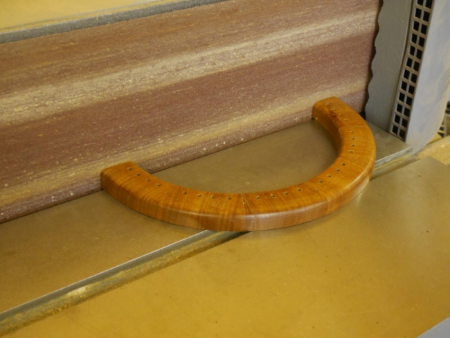
I decided to give it a clean up and polish (3 coats sanding sealer + wax polish) at this stage while it's still a simple ring:-
cl98.jpg
Next I will cut off the pattern ring and then for the 'Big Challenge'. Wish me luck - I'm flying by the seat of my pants from here on!

Brian
 

Attachments

  • cl97.jpg
    cl97.jpg
    227.2 KB
  • CAD Face.jpg
    CAD Face.jpg
    83.9 KB
  • cl96.jpg
    cl96.jpg
    220.1 KB
  • cl99.jpg
    cl99.jpg
    222.8 KB
  • cl98.jpg
    cl98.jpg
    198.7 KB
Wow!
I urge everyone looking at this not to just skim read it, but make sure to click on Brian's link, which goes to a video running on Dropbox. It must be so satisfying to hear that regular tick after so much work.
 
So I cut off the pattern ring leaving me with the face ring at the required thickness. Next, cut the ring in half radially at two of the opposite hour positions and coinciding with a pair of glue lines. If you look closely at the previous photo you'll see 12 small holes. The hole diameters are 2.5mm which represents the thickness of the slips to be glued in. The sawn surfaces were then trued up on the belt sander:-
cl01.jpg
When evidence of the little holes disappeared I stopped sanding. I could now see the ring cross section:-
cl02.jpg
(I've just noticed that there is a little smudge at the top edge which is all that remains of the little hole).
I could then scribe around the profile on to a piece of slip material. This was then shaped to make a pattern for 12 production slips (all made from a Venetian blind slat, probably ramin):-
cl03.jpg
Gluing up:-
cl04.jpg
I wasn't satisfied with the first attempt - the two half rings were slightly displaced, so I cut it up and started again, this time using the two little blocks to keep it all in line and the slips in the correct position. Repeat 5 more times.
Filling the 48 minute position holes. I needed 4mm doweling. Not readily available, but lollypop sticks are! £1.71 for 50. I've got enough for the next 20 clocks. The ends of the sticks are really clean, sharp cuts so I used these for the exposed ends of the pins. The holes were drilled at 3.5mm so the 8mm long pins needed a bit of a taper to get them started. They were just hammered in, no glue needed, using a depth gauge (a slither of wood with a 4mm hole) to get them at a uniform height. So here is the result - very satisfying to convert an idea developed on CAD into something real:-
cl05.jpg


Brian
 

Attachments

  • cl01.jpg
    cl01.jpg
    248.5 KB
  • cl02.jpg
    cl02.jpg
    216.7 KB
  • cl03.jpg
    cl03.jpg
    231.1 KB
  • cl04.jpg
    cl04.jpg
    233.2 KB
  • cl05.jpg
    cl05.jpg
    222.9 KB
Magnificent!
I especially like the name - are you ready for a complicated one now?
And also the shot of it with a plain old quartz clock ticking away in synch in the background. :D
 
That's absolutely stunning !!! Very very nicely done.

Sent from my SM-G960F using Tapatalk
 

Latest posts

Back
Top