Bifold Doors Project

UKworkshop.co.uk

Help Support UKworkshop.co.uk:

This site may earn a commission from merchant affiliate links, including eBay, Amazon, and others.

Orcamesh

Established Member
Joined
16 Sep 2003
Messages
496
Reaction score
1
Location
Berkshire
It looks like my display cabinet project is going to have to take a back seat for the moment, or be completed at an even slower pace (if that is possible). The house is still being refurbished/decorated which is what I have been up to recently, and now I need to design and build some bifold sliding doors to fill a large opening between two rooms. Mrs O would like them made in oak (solid). That's fine by me.

But having never made any bifolds before I think I may need some pointers/help...

Overall the opening is 2170mm wide by 2030mm high.
I have decided to use a 25mm thick by ~150mm wide oak square outer frame into which a further door hanging frame is attached with an upper runner & doors. The door hanging frame will be about 35x50mm cross section. The outer frame is needed for aesthetics and to cover up what is a large slot in the floor, 150mm wide, which housed the old step for what was the original french doors which used to open into the garden before the extension room was built.

There will be 4 doors altogether, 2 on each side with a central opening, each pair of doors making the bifolds.
This means each door will be ~470mm wide, so each pair will be ~940mm wide when closed.
The style will be shaker, simple stiles & rails, with as yet undecided number of rails to split the glass into smaller pieces.

I have no idea at the mo how heavy each pair of doors will be, need to make some calcs...
But my main concern is what kind of glide or roller rail system I need and this will be in some way determined by the weight of each pair of doors. I would like only a rail at the top, none at the bottom.
I have tried searching for such rail systems for bifolds but there are so many and some seem to spec what thickness of door you should use with them, usually not equal to 35mm (standard internal door thickness).
I figured that I would just make them the same thickness as standard doors (35mm), but maybe this is not needed?

Has anyone made any bifolds before and able to advise?
If so, where did you get your rail system from?
What hinges did you use?

Hope someone can help?
cheers
Steve
 
Having done some more searching I found this, which seems pretty good...

http://www.pchenderson.com/sliding_...stic&range=Room+Dividers&id=130&accessory_id=

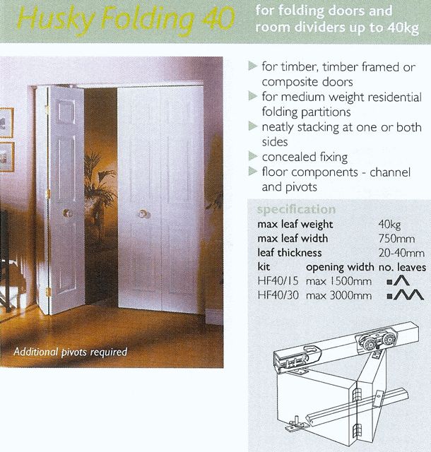
The HF40/30 Husky folding Kit seems to fit my measurements and is £138+vat which seems ok.

But it has a bottom rail, so it seems I will have to install one of these too. Oh well, I'm sure it's straight forward.

I can't believe my doors will weigh more than 40kg!
 
Yes that's who I used for the set I made a while back. Mine were in softwood so not so heavy but they didn't need a bottom rail. They came as a kit complete with all of the hinges,rail, runners. ETC.
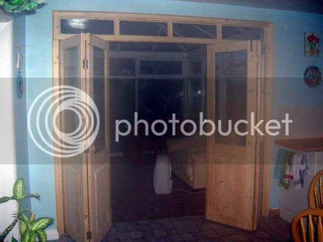
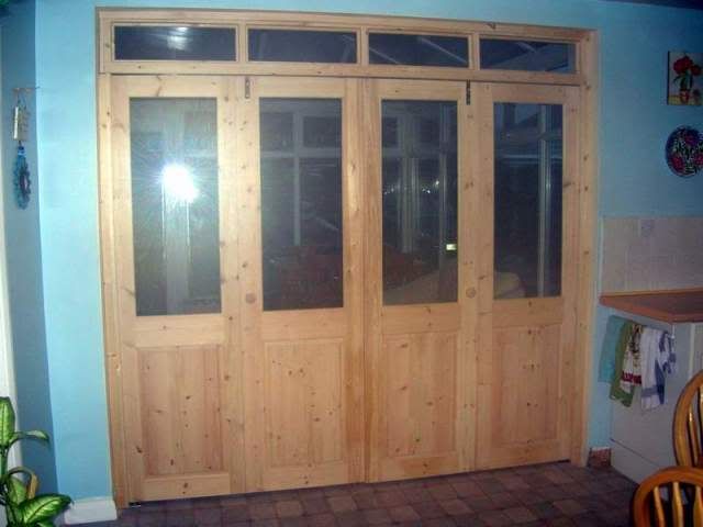
these are the ones I made and fitted:
Z6fittedopen.jpg

Z5fittedclosed.jpg
 
I've used the Husky gear several times for internal doors and it should do fine or if the weight comes out higher use the next one up. The floor guide is optional but I have not used it on any that I have fitted.

having said that the sliding/folding types with top and bottom rails do run a lot smoother but cost quite a bit more? The vista fold works well

http://www.barrier-components.co.uk/har ... ld_timber/
 
Thanks Mailee and Jason

It's always good to know that certain hardware has been used somewhere and it works. I'm sure there are some poor quality runner systems out there. I'll do some calcs on the weight of each panel once I have completed the design. Then I can choose the right runner system.

I have another question, when you make doors Mailee, I see that you leave the stiles longer than the top/bottom rail until you have glued the door frame together and then cut the ends off afterwards, what is the reason for doing this? I have never understood why this is done, is it because it avoids the corners of the doors getting damaged during the making process or is there some other reason? Or is it just to ensure that the stiles are cut exactly to the face of the top/bottom rails? I've seen this online and in books elsewhere too but never with an explanation.

cheers
Steve
 
Steve - I'm just coming to the end of a bifold project, but these are 2 x 3 door fully double glazed external sets so I suspect rather heavier than you can expect on an internal set. I used Centor E3 sliding gear which came in at about £500 for each set of 3, so a bit pricey but superb quality and action. Each door is approx 580mm wide and fully glazed weighs in at 45kgs, but they still slide with the touch of a finger. The E3 gear can carry up to 100kgs per door, and the lighter weight E2 up to 40kgs.

The Centor gear comes as a complete package which includes all hinges, stainless screws, rail, sliding gear, top and bottom bolts etc. I think you'll need some sort of rail at the bottom though to keep the doors upright as they are folded back unless you plan on keeping them very light-weight - which doesn't sound likely in oak! This bottom rail can of course be recessed into the floor so there would be nothing to trip over.

"Horns" are left on the stiles top and bottom to protect the corners from damage whilst they are stacked up in the workshop. Also, allegedly, as the fitting tolerances for bifolds are pretty tight, in the hypothetical event that you end up with doors that are a bit short you could, I suppose, add an extra few mm on to the top or bottom of the door between the horns before finally committing to the finished size. :-# :-"

I'll do a write up when I get that "round tuit".
 
Another one for the Husky Kit

Orcamesh":2kquzleu said:
Thanks Mailee and Jason

It's always good to know that certain hardware has been used somewhere and it works. I'm sure there are some poor quality runner systems out there. I'll do some calcs on the weight of each panel once I have completed the design. Then I can choose the right runner system.

I have another question, when you make doors Mailee, I see that you leave the stiles longer than the top/bottom rail until you have glued the door frame together and then cut the ends off afterwards, what is the reason for doing this? I have never understood why this is done, is it because it avoids the corners of the doors getting damaged during the making process or is there some other reason? Or is it just to ensure that the stiles are cut exactly to the face of the top/bottom rails? I've seen this online and in books elsewhere too but never with an explanation.

cheers
Steve

All very hush hush I'm afraid :mrgreen: :mrgreen: (hammer)

It stops the ends from splitting when you are cutting your mortice and gives you a bit of wiggle room to square things up as well.
Also handy for transporting them as well as it can offer some protection when they are dropped
 
Also stops you splitting out the short piece of wood on the end of the mortice when you drive in the wedge.

J
 
OK, thanks chaps, very helpful.

I think I will go for the Husky 40 system because that will be more than man enough for my doors & bit cheaper than the Centor E3.

Now I need to order the oak, bring it home & get it settled in... :)

cheers
Steve
 
One other thing I forgot to ask is whether it is important to use quarter sawn oak for the stiles in the door panels or leaves? I guess it doesn't matter much about the rails.

Obviously I want to minimise the movement across the width of the opening as these doors will be solid oak construction.

cheers
Steve
 
Well now the other project is finished I can now crack on with this. The oak (10 cu ft) was brought home in June (nearly broke the roof rack!) and has been in my workshop waiting to be planed. I've now done the initial planing (32 -> ~28mm) of the first 3 boards for the framework. The 4th board will be planed today/tomorrow. You can see the boards before planing and in stick below. Man, these boards are heavy and difficult to plane on this smallish Scheppach planer. It has tested me this week. I'm planning on following RogerM's bifold project, although mine are internal doors, not external. I may be sending Roger a pm soon...!!! The Henderson Husky 40 kit has been assessed and it seems that the edges of the doors nearest the framework will need about a 6-7mm gap which is a bit big, I wanted to shut off the two rooms, so looks like I'll have to build some sort of extra framework to hide this gap but still allow the bifolds to open, or I can shape the edges of the doors which hinge next to the framework so that the corners don't dig into the framework. Another way would be to cut a channel down the side of the framework so that the corner edge of the door can swing into it when the door is being opened. Decisions decisions...

Also with the boards in stick as you can see, some of the sticks can still be moved with your fingers even though there seems to be weight from either the above oak board and/or the weights used. I would have thought that these sticks would be quite firmly held in place. But I guess the wood is pretty strong.

Thanks for looking, all comments welcome as always...
Steve
 

Attachments

  • Bifold_doors26.jpg
    Bifold_doors26.jpg
    138.9 KB
  • Bifold_doors24.jpg
    Bifold_doors24.jpg
    173.2 KB
  • Bifold_doors22.jpg
    Bifold_doors22.jpg
    175 KB
  • Bifold_doors17.jpg
    Bifold_doors17.jpg
    172.7 KB
A good start! Some serious lengths to plane there. I wouldnt leave that tool box on your nice oak though, there is a tiny chance it might stain it.
 
+1 re the steel box on the oak. I'm looking forward to watching the progress on this one as well. Planing long lengths of timber on a small p/t - I remember it well! (hammer) :D

10 cu ft of oak on the roofrack? Blimey - that must be somewhere in the 150 - 200 kgs range.
 
OK thanks for the heads up on the toolbox, it has now got a manmade board between it and the oak.

Yep, this oak is VERY heavy and difficult to push across the surface planer in particular. Setting up the thicknesser and roller guides each time you want to change the thickness on the machine is a right pain in the @r$e!

As for the roof rack it took me ages to load it on my tod and work out how to strap it down etc. Then had a very slow drive home over about 15 miles. When I got home I realised that the roof rack had been distorted and took some surface paint off the top of the car. Not good. So I now know the limits of a roof rack. Luckily the car isn't brand new. If I'm ordering that much in the future I will deffo be paying for delivery! :oops:

Roger, when you made your framework what type of joint did you make in the top corners? I've seen your scribed bottom corners but there wasn't much said about the top corner joints.
 
Orcamesh":2bhnzwu5 said:
Yep, this oak is VERY heavy and difficult to push across the surface planer in particular. Setting up the thicknesser and roller guides each time you want to change the thickness on the machine is a right pain in the @r$e!

Yep. I remember it well. I found that for surface planing it helped to re-wax the tables and the fence frequently and to have the rollers set very marginally higher than the table (no more than 1mm) so that the board would just touch the table when it sagged under its own weight, or with a little help from me pushing down on it as I pushed it across the table.

Orcamesh":2bhnzwu5 said:
Roger, when you made your framework what type of joint did you make in the top corners? I've seen your scribed bottom corners but there wasn't much said about the top corner joints.

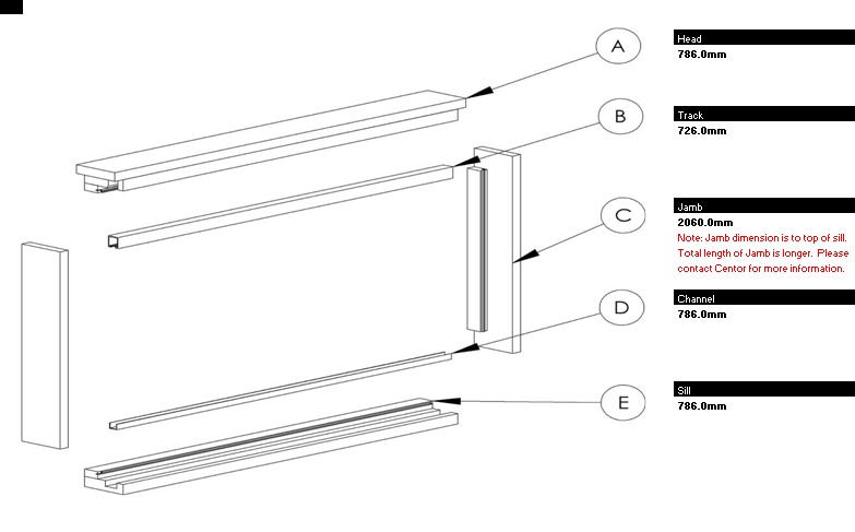
I kept it very simple, and just followed the drawing provided by Centor, with just one difference. Basically, I cut the head pieces that sit either side of the top track short by the thickness of the jamb at each end. Then the head piece (labelled A in the diagram below) sits on top of the jamb and the width of the opening is then defined by the lengths of the pieces that sit either side of the track. These are cut at the same time as the equivalent pieces that sit on the cill so that the opening will be precisely square. Then I cut a simple m&t the same thickness as the track into the head (mortise in the head, and tenon in the jamb) to register the position of the jamb flush with the front and back of the frame. Hopefully this diagram will help - remember it doesn't show my m&t modification. For assembly I just put hefty screws horizontally through the jamb into the channel supports, and down through the head into the jamb either side of the m&t, and finally another horizontally through the tenon into the head.

Bifold%2520frame.jpg


Once assembled, I squared it up by measuring across the diagonals until they were as near equal as i could get them, and then screwed a diagonal piece about 2m long across one corner to hold it square until fitting was complete.
 
Thanks Roger, I figured it might be something like that. Good idea to use M&Ts for registration. I thought about using biscuits but unsure whether they would be strong enough with this heavy oak.

The doors will need a 6mm gap between each of the doors nearest to the wall/framework on either side. My doors will be pairs and will slide towards the left and right.
Husky 40_13.jpg

This is the problem gap I have mentioned before and needs to be addressed somehow, i.e. I don't want a gap!

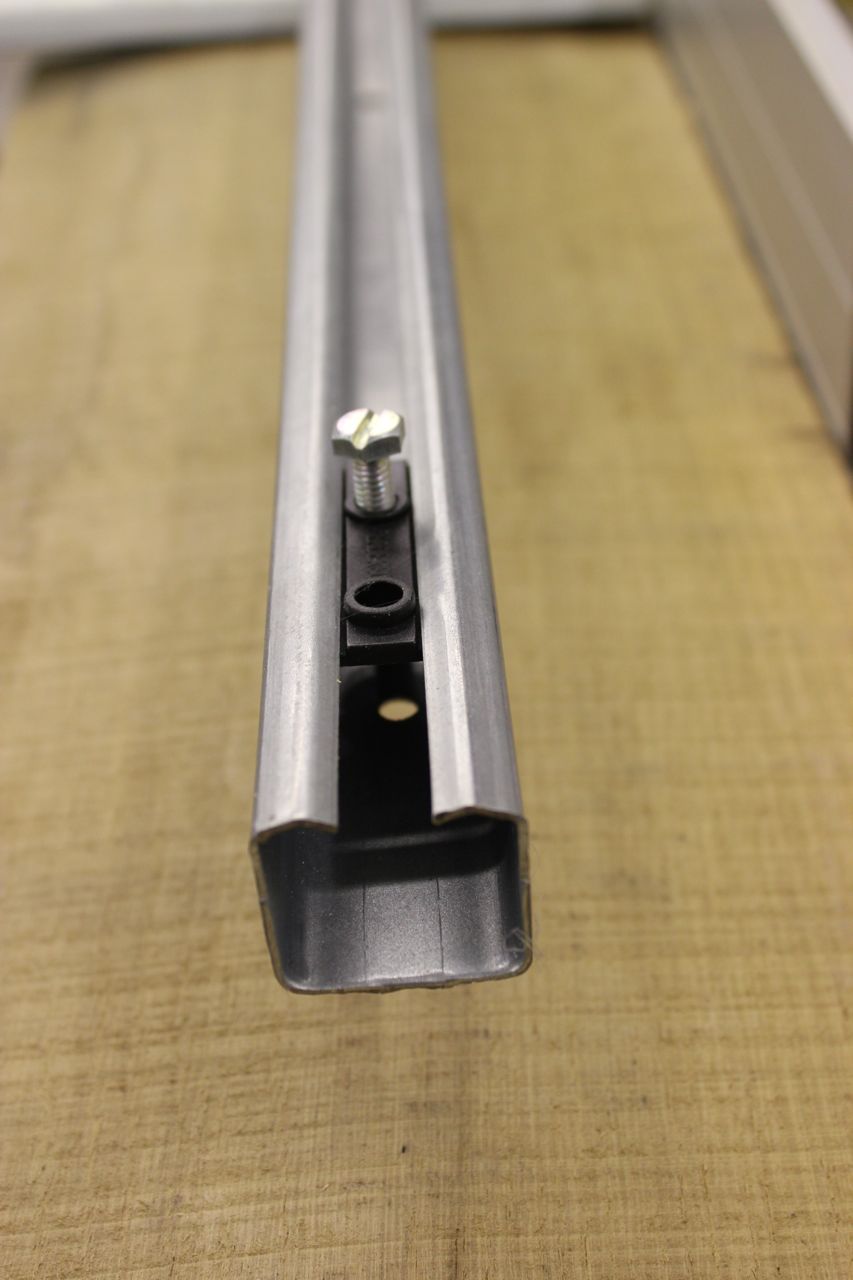
The top rail is probably similar to yours and has a double wheeled roller. The optional bottom rail is a guide rail only, i.e. there is a bearing guide pin which runs in it.
Husky 40_09.jpg

Top rail
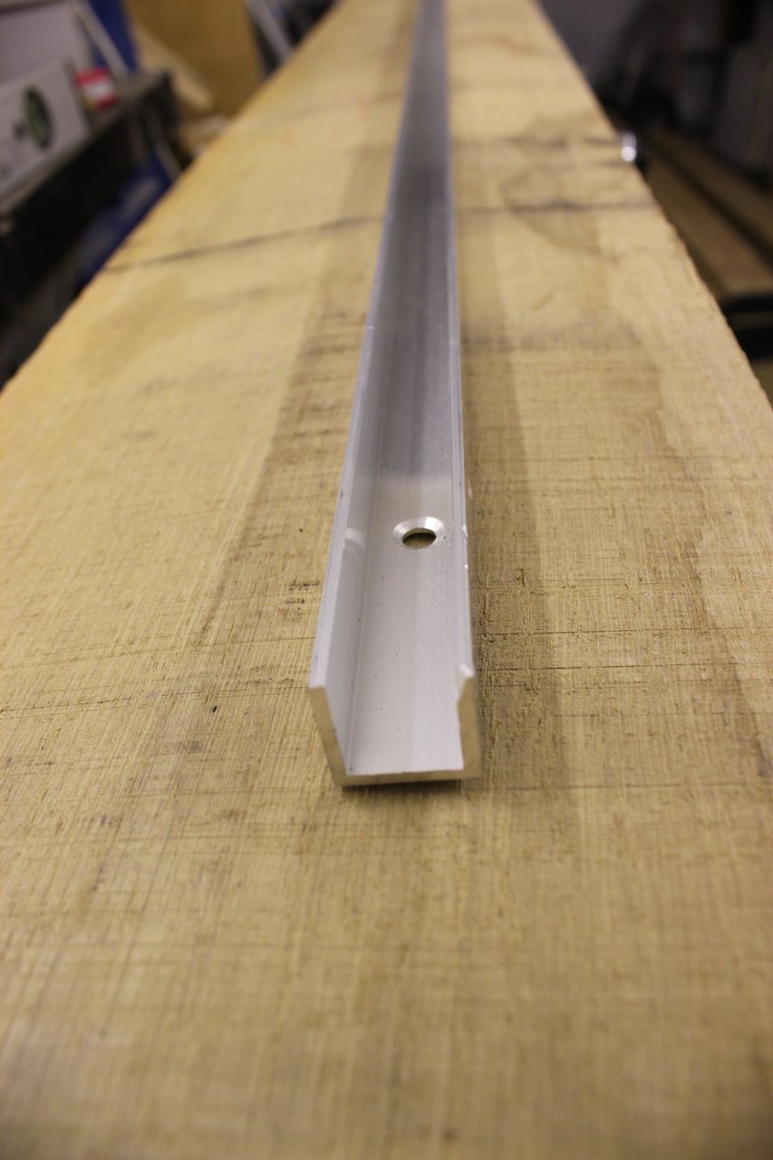
Husky 40_03.jpg

Bottom rail
Husky 40_01.jpg

Wheel roller
Husky 40_06.jpg

Various other bits here, the top right piece is the bearing guide pin. The other two pieces are used together for pivoting the doors nearest the wall.
Husky 40_07.jpg

Like so...
Husky 40_08.jpg

To fix the gap issue I could roundover, chamfer or bevel the doors nearest the wall/framework so that as they rotate, the chamfered corner does not hit the framework. Like so...
Husky 40_04.jpg

This is just a test piece I rigged up and placed against the top rail to see how it would work on the gap removal.
 

Attachments

  • Husky 40_13.jpg
    Husky 40_13.jpg
    21.9 KB
  • Husky 40_09.jpg
    Husky 40_09.jpg
    182.1 KB
  • Husky 40_03.jpg
    Husky 40_03.jpg
    82.8 KB
  • Husky 40_01.jpg
    Husky 40_01.jpg
    100.5 KB
  • Husky 40_06.jpg
    Husky 40_06.jpg
    126.1 KB
  • Husky 40_07.jpg
    Husky 40_07.jpg
    115.4 KB
  • Husky 40_08.jpg
    Husky 40_08.jpg
    127.4 KB
  • Husky 40_04.jpg
    Husky 40_04.jpg
    113.1 KB
Continued...

My cill will be something like this...
FSD_Cill_Sketchup.jpg


Double bevelled because the trench in the floor is about 20mm deep and the bottom rail is 20mm deep so it needs some wood under it for support IMHO. Max thickness of the cill is 35mm and width 150mm. The carpet in the dining room will meet one side, top surface of carpet will meet the bottom of the slope. The other room currently has a laminate floor but will be changed in near future and so I am not bothered if there is a slight step there or not. I could of course not have the bottom guide rail at all and make the cill only 20mm thick and rectangular cross section, easier to make! But I feel that I am going to need guide pins on these bad boys!

Doors will not be same as these but this gives you an idea of how it works and looks...
Husky 40_14.jpg

The doors have to be slid onto the top rail before the top rail can be screwed home. So the top rail cannot be the total length of the inside width of the framework and a small gap must be provided at each end so that the rail can be swivelled out as shown below (No.7)...
Husky 40_11.jpg

I intend not to glaze the doors until they are hanging. So will use suction cups to lift glass into position before nailing in the beading.

Does anyone know if there is a minimum thickness of tempered glass I should be using for internal doors? I thought maybe 4mm was enough? I will be using a single pane of glass in each door which will be about 350 x 1800 mm.
 

Attachments

  • FSD_Cill_Sketchup.jpg
    FSD_Cill_Sketchup.jpg
    169 KB
  • Husky 40_14.jpg
    Husky 40_14.jpg
    86.4 KB
  • Husky 40_11.jpg
    Husky 40_11.jpg
    132.6 KB
Very interesting! Thanks for posting.

Not sure that this is a job for biscuits. My m&t between the jamb and head was really nothing more than a simple box joint with one tooth on the jamb and a corresponding slot that coincided with the head rail thickness. Once thats engaged there really is nowhere it can go, and having one less variable when you come to install the frame can only assist you because I can assure you that you'll be a busy boy focussing on other areas! :lol:

Is the 6mm gap between the doors and the jamb such an issue? When the doors are closed presumably you'll have a "stop jamb" as you would on an external door to conceal the gap. That will stop any light shining through which is what makes a gap obvious, and when the door is closed the gap will be covered by the "stop jamb" anyway.

I wouldn't regard the bottom rail as optional. Oak doors will be heavy. You've bought nearly 180kgs of oak for this project. OK - some will end up in the frame, and some as offcuts and some as dust/shavings - but these boys will still be heavy. I would be surprised if, when glazed, they are less that 30kgs each. You say you already have a 20mm slot in the floor (solid?). This sounds a bit thin to be the total thickness of screed over the slab. If you wanted to be really anal about it you could deepen the slot down to the floor slab - probably a total of 50mm - and that would totally contain the floor rail flush with the final floor level. No need to use anything as messy as a disc cutter. Just stitch drill along the line with your shop vac hose placed next to the drill. The screed in between the two cut lines should then lift easily off the slab. But your solution looks fine to me.

Trying to fit the frame with 4 doors already hanging from the rail sounds like a problem unless you are a 20 stone muscle bound hulk. I would be tempted to test fit the frame first, getting it as true as possible, and then drop the rail - fit the doors - and then refit the rail into an already accurately fitted frame. The plumbline method for getting the frame vertical works well and you won't have the problems of wind blowing it around as we had with fitting external doors. Just make a little line carrier to sit in the rail to hold it central.

Definitely leave glazing until after the doors are fitted. Apart from the weight issue, you'll also find the doors easier to fit if you can reach through them and hold them around the inside of the frame. 4mm toughened or laminate should be fine, but any glass provider worthy of the name will be able to advise you. A couple of lifting suckers can be bought cheaply from Screwfix and will be worth their weight in gold. This is quite an interesting site that explains the requirements.
 

Latest posts

Back
Top