A Galoot's Infill Smoother

UKworkshop.co.uk

Help Support UKworkshop.co.uk:

This site may earn a commission from merchant affiliate links, including eBay, Amazon, and others.

Derek Cohen (Perth Oz)

Established Member
Joined
2 Mar 2005
Messages
3,398
Reaction score
1,912
Location
Perth, Australia
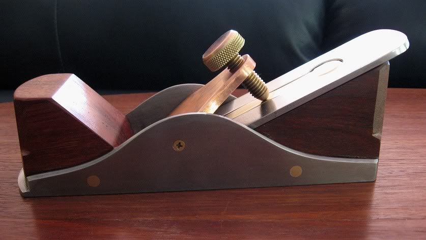
Stanleyinfill4.jpg


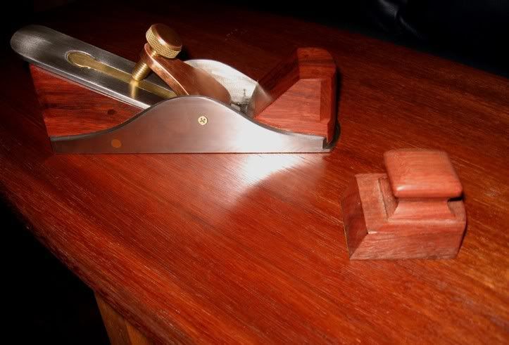
It is several years since I last built a “Stanley infill”, my previous effort based on a #4. This time I decided to use the shell of a derelict #3 Stanley to create a small smoother – the final length is just 7 ½”. I also wanted to incorporate a few ideas. So what we have here is a bevel up configuration with a 25 degree bed.

The reason for the high bed (the standard at present – from LN and LV – is 12 degrees, while Karl Holtey’s #98 is 22 ½ degrees) is to reduce the primary/secondary bevel angle. The bevel here comprises a 30 degree primary with a 35 degree micro, creating a 60 degree cutting angle.

The blade is 1 ¾” wide and 5/32” (about 4mm) thick. It came out of a Danish Langeskov woodie. No cap iron is needed. Since a solid surface was needed, I filledthe blade slot with a piece of brass. This was filed fractionally too large, then left in the freezer to shrink, before force-fitting it (a big hammer!). After it thawed the brass expanded and the whole piece became one solid affair.

The lever cap was carved (!) from a block of phosphor bronze (as I was informed) since I had nothing else to hand that was the desired thickness. This stuff is incredibly hard (I believe that it is used for bearings). It has a warm pink tone. I have used a combination of this and yellow brass throughout.

I lack metal machining tools, unless you include a drill press and an angle grinder. So the task of building a lever cap screw would be well beyond me – if I did not cheat a little. What I do is raid the local Borg’s gardening section for solid brass hose fittings and weld these together. The cap cover was a copper (Australian) 2c piece, so as to match the colour of the lever cap.
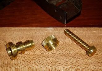
Levercapscre.jpg


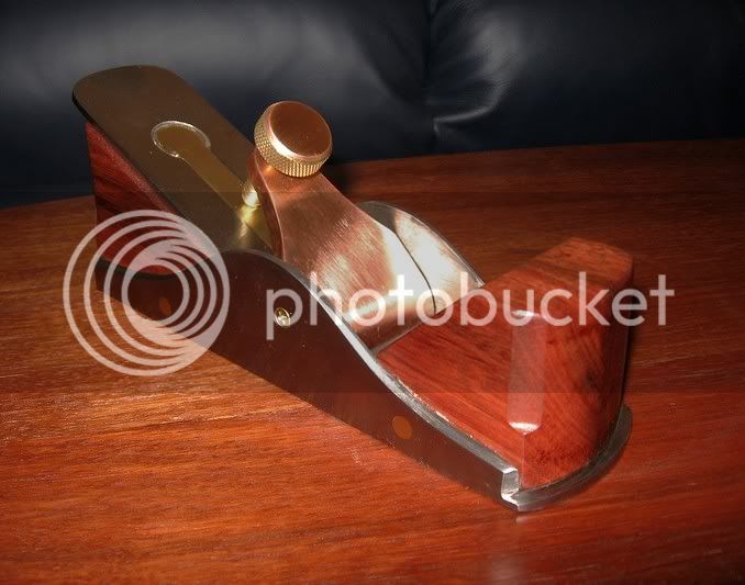
The infill is just scrap Jarrah, well seasoned but I did not have the desired thickness and had to laminate two pieces. This was shaped, then epoxied into place. For additional strength and a “a look”, brass screws were added, then filed flush.

I must admit to having ambivalent feelings about the final shape. I much prefer round to straight sides, and the result here seemed to evolve as if it had a life of its own.
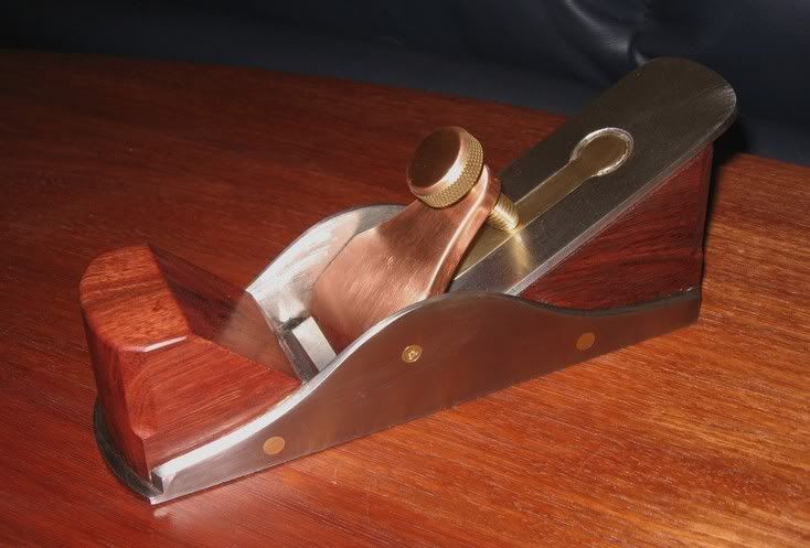
Stanleyinfill1.jpg


Stanleyinfill3.jpg


The mouth was completed last of all, deliberately made too small, and opened up gradually with files. The end result is a very fine mouth.

How well does it work?
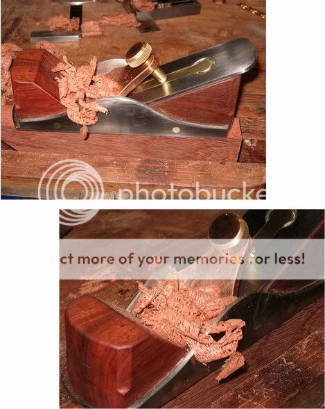
Stanleyinfillshavings3.jpg


I hope this effort might inspire a few more Stanley infills!

Regards from Perth

Derek

December 2006
 
Derek


Great workmanship - in a hundred years time, this one will drive the collectors nuts as they try and work out who made it!

How does the lever cap pivot i.e. what is its fulcrum? Do those cross headed bolts/screws go into its sides?

Regards.
 
Hi Evergreen

The lever cap pivots on two brass machine screws, one on each side. I would have prefered a non-Phillips head, but cannot find any. The plane body is drilled and tapped for the screw, and the lever cap drilled one size larger so that it just turns on the screw shaft.

Regards from Perth

Derek
 
Very nice, Derek!
Any chance of a shot of the mouth from underneath? And can I ask why you shaped the woodwork the way you did? A plan, or just the way it worked out? If I remember your last one has a cery curvy look-thi sone is more "minimal" with the shaping. (Not a critisism, just an observation!!! :D )
Using a Stanley casting saves a lot of time with the metalwork-great idea!
Cheers
Philly :D
 
very nice derek, as for the screws, maybe you should have tried machine screws, even stainless ones might well have a slotted head.

did you shorten the stanley body at all???

paul :wink:
 
Philly asked:
Any chance of a shot of the mouth from underneath? And can I ask why you shaped the woodwork the way you did? A plan, or just the way it worked out? If I remember your last one has a cery curvy look-thi sone is more "minimal" with the shaping. (Not a critisism, just an observation!!! )

Philly

Here is a pic of the underside.

Mouth1.jpg


The mouth ended up very small. I later measured this as .10mm (.004")with feelers.

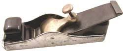
The woodwork began with the idea of recreating the look of a traditional Spier/Mathieson -type mitre plane. It just did not look right with the high bed. I tried for a "traditional" front knob ...

Mitreplane1.jpg


... but it was not a good look with the rear end.

knobchoice.jpg


So I ended up going with symmetry. Unfortunately - as I earlier said I am quite ambivalent about this - it turned out more vertical/angular than I like. I reduced some of this with chamfers on the corners. I do prefer softer curves (sexier). Still, the plane is quite comfortable - a lot more than I expected.

Paul asked:
as for the screws, maybe you should have tried machine screws, even stainless ones might well have a slotted head.

did you shorten the stanley body at all???

Paul

I, too, dislike the phillips head screws. These are machine screws (parallel sided) and it is impossible these days to find slotted versions in these parts (thinks to self - I recall using slotted ones on the #4 infill. If so, perhaps I will swap them around?).

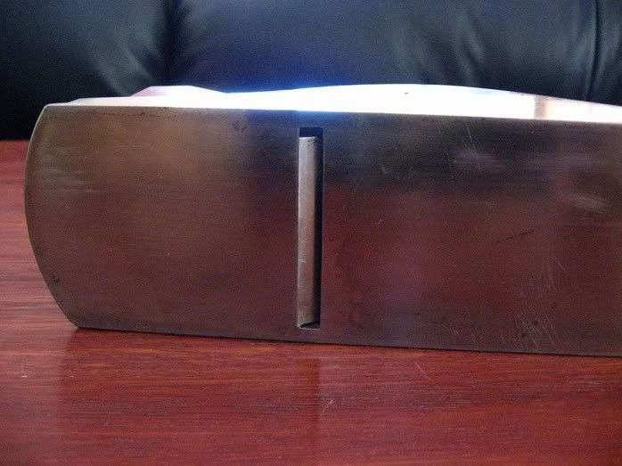
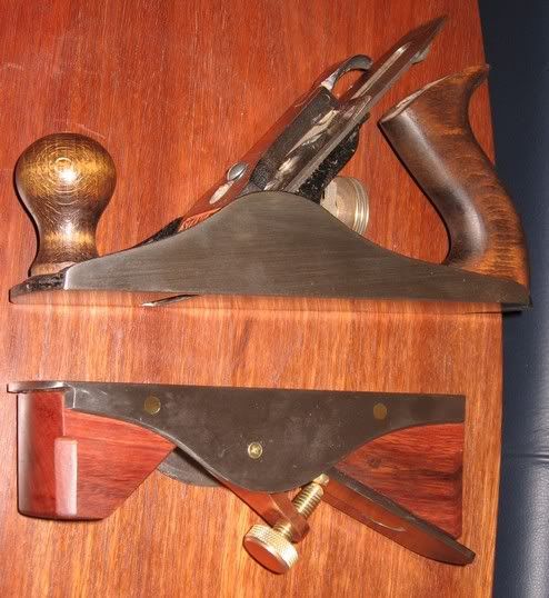
I did shorten the #3, quite a bit as you can see here:

Sizecomparison2.jpg


Bearing in mind the other thread about the length of a #3, I have a UK-built #3 that measures 240mm (approx 9 1/2"). This casting was also a UK #3, and now measures 192mm (approx 7 1/2"). It weighs about 1 oz lessthan the original, but "feels" heavier.

Regards from Perth

Derek
 
Its looks awesome and what a great idea for recycling a plane into something new. How is the infill connected to the body? I see the brass rods and am wondering if thats all there is. :-k
 
Great-thanks Derek! Good to see what you were using as inspiration, too. I think you interpreted it pretty well!
You've got me thinking, now........ :wink:
Philly :D
Apologies for the appalling typing-it was late, I'd had a couple of G+T's, etc.....
 
Derek,

Fine job!

I think your choice of bed angle is very useful considering all those cranky beautiful timbers you have in OZ.

60 degree Effective Pitch has always seemed a better starting point to me than York pitch.

It will also be easy to push this EP to 70 or 75 if necessary, without ending up having to hone and polish the blade at ridiculously steep angles.

David
 
Derek,
Great piece of work!
Can I assume that the rear infill projects into the rear area of the original mouth on the casting and that you then filed forward to get the fine mouth?
If so, does the wood support the blade 'into the gap' behind the iron?
Regards,
Martin
 
hi derek, have
you thought to try the motorcycle or car restoration guys in country.
over here people remake stainless screws in the old style,
am sure that the guy who builds Vincent engines or BSA ones over there do not use phillips style screws.

not sure about names addresses etc, but sure a man of your resources could find someone :lol: :twisted:

paul :wink:
 
Can I assume that the rear infill projects into the rear area of the original mouth on the casting and that you then filed forward to get the fine mouth?
If so, does the wood support the blade 'into the gap' behind the iron?

Martin

To fit the Jarrah infill bed I first ground out the frog bits and pieces (there was a small bump left over but I just hollowed the infill slightly to fit over this). This made it easier to slide the bed back-and-forth to adjust the size of the mouth.

To close up the mouth, I slid the bed forward until the blade edge was just below the surface of the sole. Make sure it is parallel (I did this by eye), and then epoxy it down. Later, when all was done, I filed open the mouth by approx 1 mm. This left a .10mm wide mouth.

The Jarrah bed supports the blade up to the end of the cast iron at the start of the mouth. Since the bed/sole together is quite thick, this would be about 5 or 6mm from the tip of the blade (about the same as a bevel down plane). Note, however, that this blade is thicker than the average LN blade and thicker than the LV LA Smoother. In fact, it is stiffer still when one considers that it is narrower than the latter.

Regards from Perth

Derek
 

Latest posts

Back
Top