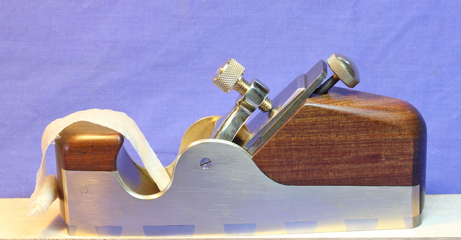
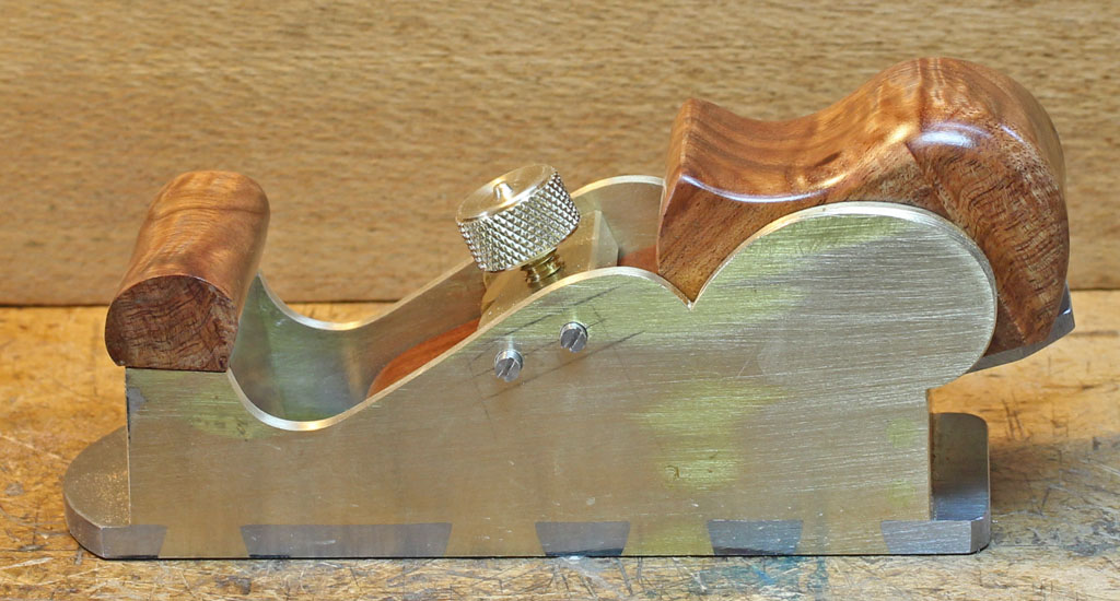
A chariot plane made from a Bristol Design casting

UKworkshop.co.uk

Help Support UKworkshop.co.uk:

This site may earn a commission from merchant affiliate links, including eBay, Amazon, and others.

rxh

Established Member
Joined
2 May 2011
Messages
699
Reaction score
77
Location
Surrey
Jim Kingshott has a chapter on making a chariot plane from a casting in his book “Making and Modifying Woodworking Tools” and he mentions Bristol Design as a source of castings. I was in Bristol in January and I paid a visit to Bristol Design and asked if they still had any bronze castings for planes. They brought out about a dozen castings for me to see: mostly for mitre planes and shoulder planes but there was just one for a chariot plane and I bought it. I was told that they will not be having any more bronze castings made.
Here are “before” and “after” photos of my chariot plane. It has a sweated-on steel sole and a Norris style adjuster. The wood is purpleheart and the iron is of O1 steel, 1¼” wide x 1/8” thick and has a bed angle of about 18°. The bridge is attached by two 4BA countersunk screws at either side and the toe is held on by 4BA bolts. The adjuster has 2BA and 4BA threads, and the lever cap screw is ¼” BSW (I like to use British threads where possible). The completed plane weighs 1lb. 4¼oz. (~0.57 kg.).
 

Attachments

  • IMG_7344A.jpg
    IMG_7344A.jpg
    234.6 KB
  • 20200416_162016C.jpg
    20200416_162016C.jpg
    250.4 KB
  • 20200117_174153C.jpg
    20200117_174153C.jpg
    243.8 KB
Well, the last casting certainly went to the right owner! That's a lovely job, as we've all learned to expect from you.
You know what I'm going to ask though - how does it perform? And can we see a shavings shot?

I'm intrigued by chariot planes. They seem to be sort of equivalent to a block plane but the short toe makes them awkward for so many jobs.
 
Thanks Andy. I tried the plane on the end and edge of a board and it worked OK but the short toe was a bit annoying as you suspected. However, I found it worked well on the face of the board and one use that I imagine would be to clean up a defect noticed on something like a fielded panel after assembly where other planes could not access.
 

Attachments

  • 20200417_173221A.jpg
    20200417_173221A.jpg
    233.8 KB
  • 20200417_172422A.jpg
    20200417_172422A.jpg
    220.2 KB
  • 20200417_170041A.jpg
    20200417_170041A.jpg
    210.3 KB
Lovely, rxh!

Looks like you have access to a milling machine & know how to drive it - wish I was so lucky..

I too would like to know what functions chariot planes were considered the answer to in their day. Jim Kingshott says he couldn't live without the one he made (coincidentally, also from a Bristol D. casting), but doesn't elaborate on why, as I recall. As Andy suggests, it's really just a prettier block plane with a bull nose, which makes it unsuitable for planing from an edge. That is one reason I made two - one being a more faithful to the original, short-toed version & one with a goodly toe. The latter gets far & away the most use. :)

Cheers,
 
Thanks IWW - I would recommend anyone wanting a chariot plane to follow your advice and excellent examples. The casting needed an awful lot of filing and scraping, and the longer toe does seem advisable. I think that construction from metal plate is a better way to go.

I only have a light milling capability: a drill press fitted with a milling chuck and cross vices. I am on the look out for a real milling machine that is not too big. Here are a few photos of my machining operations for the plane.
 

Attachments

  • 20200416_163251C.jpg
    20200416_163251C.jpg
    232.1 KB
  • 20200415_170957C.jpg
    20200415_170957C.jpg
    217.5 KB
  • 20200408_150200C.jpg
    20200408_150200C.jpg
    228.4 KB
  • 20200416_161651C.jpg
    20200416_161651C.jpg
    232.9 KB
  • 20200416_161519C.jpg
    20200416_161519C.jpg
    252.5 KB
  • 20200407_113227C.jpg
    20200407_113227C.jpg
    254.5 KB
  • 20200406_120135C.jpg
    20200406_120135C.jpg
    253.6 KB
  • 20200406_095737C.jpg
    20200406_095737C.jpg
    209 KB
I'm even more impressed, rxh! Making-do is something I'm very used to, & my own drill-press has been 'pressed' into serving in many ways it wasn't intended for, but I reckon you've shown just how much a bit of thought & patience can achieve.
The advent of a small metal lathe has relieved my DP of some of the more onerous demands I put on it in the past (like knurling 18mm diameter brass) & I've long been thinking about acquiring a small milling machine myself. A decent small machine isn't cheap & I'd need to spend about as much or more on the accessories, so it would represent a substantial outlay (& a steep learning curve, having only ever used one very briefly & under strict supervision!). So I shilly-shally endlessly, telling myself that I'm really a woodworker & metalwork is only a means to a more desired end, so if it requires making do & a bit of extra time & maybe not quite as good a result, then so be it. You have amply demonstrated that it doesn't have to result in an inferior product!

Yes, I think fabricating a body is less work than cleaning up a casting if you don't have 'proper' machinery. Making a mouth for a low-angle plane is slightly challenging. There is no way I can see of doing it with hand-tools without splitting the sole - the mouth would end up bigger than a politician's if you tried to file it from the solid as you do for bevel-down standard-pitch blades. When I first read about the tongue-& groove joint to re-join the pieces I recoiled in terror - way too hard! However, once I got down to it, it turned out to be far easier than I expected, & I've done 3 now, getting a bit better each time (insofar as eliminating evidence of the joint goes, at any rate).
:)
Cheers,
Ian
 
Thanks Ian. I agree that it would be very difficult to make a suitably narrow mouth by hand in a one piece sole for a bevel-up plane. I started to make a plane with a two piece sole but I was not satisfied with my tongue and groove joint and I put it to one side. I'll probably put it down as a learning experience and start again from scratch. I don't like to be beaten.

I think a good one piece sole is quite tricky to make by machine. A while ago I built a Spiers style mitre plane from a Shepherd kit. It came with the mouth already milled but I had to do quite a lot of work on it. The worst part was that the mill cutter had left rounded ends that I had to work on with rifflers to provide access for the iron.
 

Attachments

  • IMG_3487C.jpg
    IMG_3487C.jpg
    215.6 KB
  • IMG_3488C.jpg
    IMG_3488C.jpg
    209.8 KB
Hmm, I don't think the kit makers thought things through very well! For starters, it's typical to have a wide pin beside the mouth so that the peening will occur over solid metal. You are going to get significant distortion of the front 'pin' there, unless you jam a piece of scrap steel in the throat between the unsupported flanges.

As I said elsewhere, making a split sole & T&G joint isn't as difficult as I first thought it would be, so don't be put off. It does require care & patience, but it's vert satisfying for an inveterate tinkerer like myself when it works out. My tips are: use a new hacksaw blade to give the cleanest cuts, & clamp a hardwood guide on the sole to help keep the blade square & as close to the layout lines as possible. The grooves can be roughed out with a jewellers' saw & cleaned up with a very thin file (I laid mine out to match the thinnest file I have), but most files don't cut a perfectly square corner, so I ground a chisel edge on the end of a needle file & scraped & pared them square with that.

On all 3 split soles I've made so far, a slight dip occurred in the sole after peening, due to the 'loose' ends being forced down slightly. I was very meticulous in getting the bottoms of the tail sockets dead straight and had the parts well-clamped to a hardwood peening block, but the two part soles all ended up slightly concave near the join. It was only slight and lapped out easily enough in the final clean-up, so it wasn't a big deal, though it did alarm me when I first started lapping & saw only the toe & heel contacting the plate!

Cheers,
 
rxh":1qt9ly3n said:
Thanks Ian. I agree that it would be very difficult to make a suitably narrow mouth by hand in a one piece sole for a bevel-up plane. I started to make a plane with a two piece sole but I was not satisfied with my tongue and groove joint and I put it to one side. I'll probably put it down as a learning experience and start again from scratch. I don't like to be beaten.

I think a good one piece sole is quite tricky to make by machine. A while ago I built a Spiers style mitre plane from a Shepherd kit. It came with the mouth already milled but I had to do quite a lot of work on it. The worst part was that the mill cutter had left rounded ends that I had to work on with rifflers to provide access for the iron.

Nice job on the first plane. Looks wonderful.

I have exactly the same Shepherd chariot plane kit, but my most advanced machine tool is a file. I bought the chariot kit with a long panel plane kit, made (eventually sold) the panel kit and have held on to the chariot kit because I think it would be bordering on unethical for me to sell it to an unknowing person.

All of the other kits I've had, I've made, but I've noticed that the kits must seem a good idea at first and never are successful enough to be refined into something good. The shepherd panel plane had a terrible iron, the cap iron was sort of an afterthought, and the sides were drilled so that the lever cap wasn't in the right place to lock things down (too far from the bed). Maybe the cap was thicker on an earlier version before they got cheap. I had to pein a spacer to the top of the cap iron so that the screw could reach it.

I also put a st james bay kit together, and it was better (far cheaper), but the mouth is the same width as the plane, and pre-cut with rounded corners in the cut (so you have to clean the corners out and take great care not to widen any other part of the mouth or it will go outside of the plane sides and look ugly).
 
Hmm, reading D.W.'s post makes me wonder how many 'kits' are languishing unfinished in sheds around the world. A panel-plane kit I put together had been sitting untouched for close to 30 years before I got hold of it. It also had 'problems', due to the roughly-cut dovetails, but no holes had been drilled in the sides, so at least I didn't have trouble with placing the lever cap!

For those who've not made a plane but harbour a secret desire to do so, it's like so many other things in life, only half as difficult as you imagined before you started. Kits may offer what seems like an easy road, but I'd go that route with caution after my own & others' experiences. Cutting out your own parts from scratch is very easy - buy a cheap jewellers' saw but use only top-quality blades like Glardon, Pike or Eberle, and it's a doddle. Likewise, don't waste your money on cheap files, they are likely to frustrate you to the point of despair.

Out of curiosity, I used a Veritas kit intended for making wooden-bodied planes as the basis for a small rear-bun infill. I was mainly interested in how the adjuster would work:
Final fettle.jpg


The answer was "not very well", I'm not a big fan of the Norris adjuster, and the coarse-threaded thing Veritas used is elegantly simple, but very hard to make fine adjustments with! The newer fine-thread version would go a long way to improving it, I think, but have not tried one, yet.

The kit I used had its own problems when used as I did, the thumbscrew for the lever-cap is designed to fit in the thin wooden 'lever wedge' as shown in the instructions & is too short for a more conventional fixed lever-cap like I used above. That wasn't a big deal for me, but not everyone has access to a metal lathe. Also, if you are a believer in cap-irons, you will need to make your own. Again, that's a relatively simple exercise and doesn't require any elaborate tooling, and there is a hole in he blade you can use for the retaining screw (albeit a little wider than needed).. I used a bit of 2mm stainless steel (found a 100 x 100mm sheet for $10 on ebay) which worked very nicely.

In retrospect, I wouldn't bother with the kit, the only parts you need are the blade and the adjuster (if you must have one), which is sold separately and is very reasonably priced (but only works with Veritas blades unless you make your own blade). There are various ways of doing a home-baked thumbscrew that can look the part, and cutting out & shaping a lever cap from a bit of 9 or 12mm brass is far easier than I thought it would be...

So, if the thought of having a crack at an infill has been dogging you for some time, just go ahead & do it....
:)
Cheers,
 

Attachments

  • Final fettle.jpg
    Final fettle.jpg
    109.8 KB
This thread reminded me I'd had the parts for a small chariot plane cut out & sitting on my bench for about 4 months or more. They were well-covered by other junk, which is partly why it had sunk off the screen! :( . So I decided it was high time to finish it off, and the couple lessons I learned might have some relevance to this thread. This is my 4th or 5th split-sole plane now, & I'm definitely still on the learning-curve, as I discovered!

Lesson #1, is, if you are going to put something aside for a while, make sure you document any changes of plan that occurred. This plane was to have a long-ish toe & I'd got as far as splitting the sole & forming the tongue & groove joint, but not forming the bed bevel. I knew I'd decided to change the bed angle I'd drawn on my initial sketch from 15 to 19 degrees, & I had scribed the lines for the mouth bevel, so I reckoned they must be correct, so I went ahead and cut a series of hacksaw cuts to make little fillets that I could chisel out to get rid of the bulk of the waste. It was only when I made the guide-block (for the higher angle) and clamped it to my sole that I realised I'd been working to the lower bed angle, & hacksaw cuts went a bit far back. It meant that I had to file more away from the front than I wanted, to to get a clean bed. Lesson #2 - always check & re-check!
1 a filing bed.jpg


On a rough test, holding the blade in position, it seemed ok; it looked like the mouth would be larger than planned, and allow little or no room to file the front & finesse it, as I would usually do after lapping the sole, but as long as I worked carefully, I reckoned it would be fine.

I didn't keep a lot of progress shots, sorry - I wasn't planning on showing the stages of the build, but here is the body with the D/Ts fitting & ready to pein. The tails are a good fit in their sockets, making them easier to fill, & most importantly, the two pieces of the sole are tight & straight:
1 Ready to pein.jpg


So we jump next to fitting the bridge & woodwork, always a bit tedious as any infill maker knows. The wedge/lever was simple enough, but the small over-stuffed infill for the front bun/scroll was rather small & hence very fussy to fit tightly:
2 Fitting wood & bridge.jpg


Jumping forward another day & it was ready for lapping, & after getting the sole roughly flat, I put a blade in to check the mouth. Drat! It turned out quit a bit wider than my earlier check had indicated. Compare the new plane (right) with one that has a 'proper' mouth:
3 Mouths.jpg


The light coming through the gap reflects off the blade bevel and makes both mouths look bigger than they are, but the one on the left is what I was aiming for (something between 0.2 & 0.5mm), while that on the right is more like 0.8mm. Lesson # 3 - check more carefully next time!

So I carried on lapping, and got it to the stage where I could give it a test-run. There's still a small low spot beside the mouth, where the front piece has depressed a bit under peining. It's not actually impinging on the mouth proper, and won't affect performance, but it's an annoying imperfection in an otherwise satisfactory assembly job:
5 Lapped b.jpg


The story hasn't ended too badly, it's a beaut little plane, and on fairly benign wood it had no problem dealing with some reversing grain. I spent far more time testing than was necessary, just for the pleasure of feeling it snick across the test piece & watching it throw out fluffy shavings:
6 It works.jpg


Perhaps it was fate telling me I really needed a more 'general purpose' plane - the fine-mouthed thing shown above does have a tendency to choke if I get a bit enthusiastic with shaving thickness. Not sure why that is, the gap is actually bigger than the thickest shaving I would want to take, but quite a few of our hardwoods just have this tendency to pack in the mouth gap, despite there being what looks to me like adequate relief on the front side of the mouth.

I will probably add a screw adjuster, even though I'm just as happy to use the tippy-tap method, but I won't do that 'til I get a permanent blade for it (testing was done with a 'borrowed' blade). I was thinking of putting a PM-V11 blade in this one, as I've become rather fond of the stuff for its ability to cope with our absurdly hard woods. In the meantime, it goes into the tool cupboard & sea-trials start in earnest as soon as its new blade arrivese....

7 Done.jpg


Cheers,
IW
 

Attachments

  • 1 a filing bed.jpg
    1 a filing bed.jpg
    113.6 KB
  • 1 Ready to pein.jpg
    1 Ready to pein.jpg
    164.6 KB
  • 2 Fitting wood & bridge.jpg
    2 Fitting wood & bridge.jpg
    156.8 KB
  • 5 Lapped b.jpg
    5 Lapped b.jpg
    128.5 KB
  • 6 It works.jpg
    6 It works.jpg
    160.1 KB
  • 7 Done.jpg
    7 Done.jpg
    138.4 KB
  • 3 Mouths.jpg
    3 Mouths.jpg
    104.9 KB
Back
Top