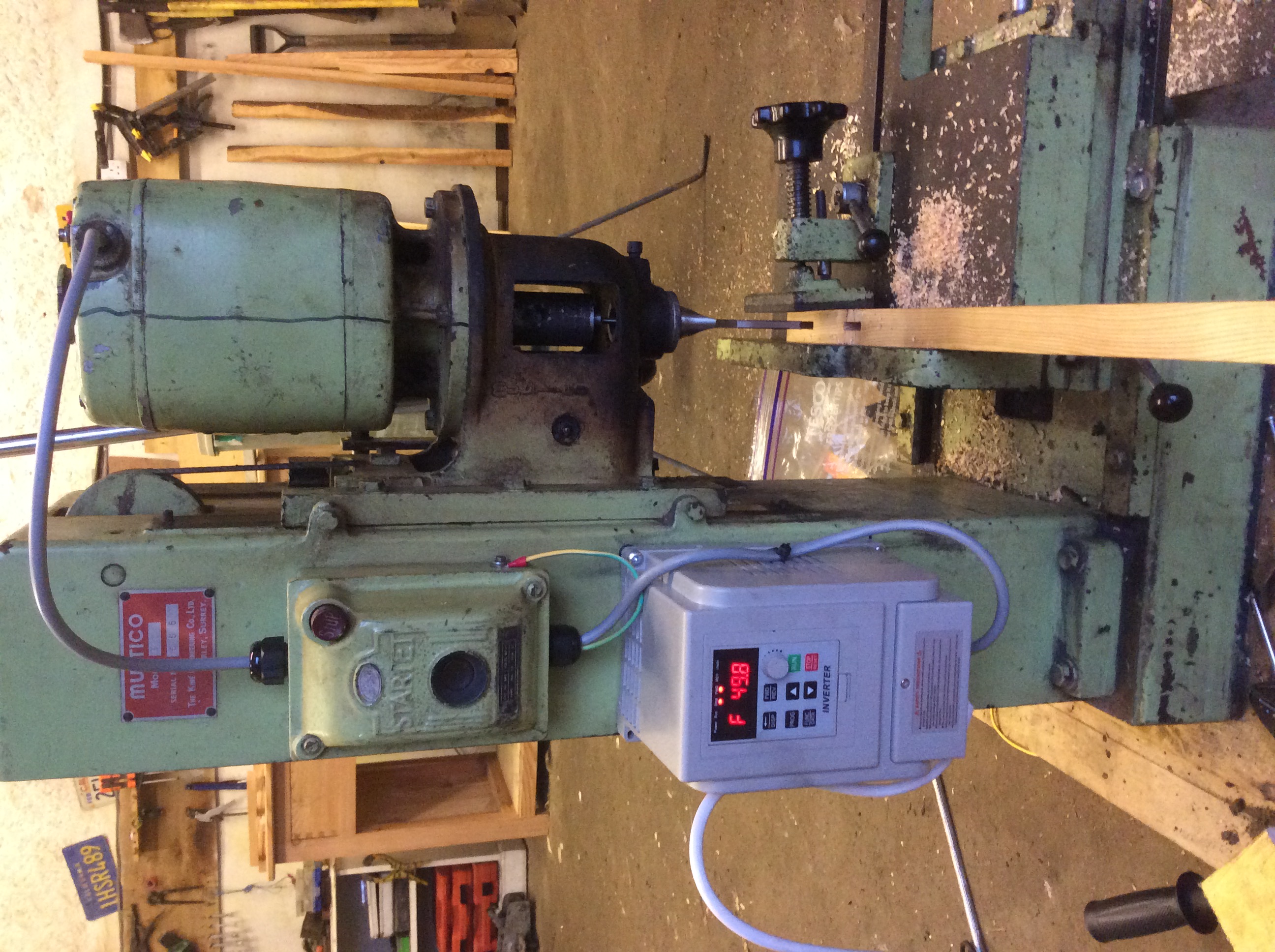
Multico Model K mortiser single phase conversion

UKworkshop.co.uk

Help Support UKworkshop.co.uk:

This site may earn a commission from merchant affiliate links, including eBay, Amazon, and others.

guineafowl21

Established Member
Joined
28 Oct 2015
Messages
890
Reaction score
395
Location
Nairn
I bought this fine, old and very heavy machine for £150 (seller’s picture):
E1A2C5D9-2FBA-485D-B7A5-011ED3DA8457.jpeg


It’s a pre-1970 model, three phase and wound permanently in star, so required 3ph with 400V phase-phase, rather than the 3ph/230V ph-ph which a normal inverter drive would provide.
 

Attachments

  • E1A2C5D9-2FBA-485D-B7A5-011ED3DA8457.jpeg
    E1A2C5D9-2FBA-485D-B7A5-011ED3DA8457.jpeg
    306.2 KB
After opening the motor up, I had a dig in the windings and found the star connection:
00183DA2-F472-4F42-983F-C0D59213E0E6.jpeg


Close up:
98DA2653-95C6-4945-B1AC-C3EB8A9B04C5.jpeg


I brought the three new wires out the the paxolin panel:
092B5AD3-7CED-4A42-8B23-0EFFC6F8E82E.jpeg


After labelling the connections, I could then configure in delta with straps:
EF1B0666-20A7-4EFE-81AA-DCB5EA6087FD.jpeg


A cheap and cheerful, 1ph-3ph inverter later, the mortiser was working... (sorry for the sideways look - it’s the right way up on my computer:
2A28F150-1A65-42C8-B3FF-A5939105D3EF.jpeg


...and makes short work of mortices, even through knots!
04428F9C-5D40-456D-B3F2-0C76709B1323.jpeg
 

Attachments

  • 00183DA2-F472-4F42-983F-C0D59213E0E6.jpeg
    00183DA2-F472-4F42-983F-C0D59213E0E6.jpeg
    1.4 MB
  • 98DA2653-95C6-4945-B1AC-C3EB8A9B04C5.jpeg
    98DA2653-95C6-4945-B1AC-C3EB8A9B04C5.jpeg
    1.1 MB
  • 092B5AD3-7CED-4A42-8B23-0EFFC6F8E82E.jpeg
    092B5AD3-7CED-4A42-8B23-0EFFC6F8E82E.jpeg
    1,016 KB
  • EF1B0666-20A7-4EFE-81AA-DCB5EA6087FD.jpeg
    EF1B0666-20A7-4EFE-81AA-DCB5EA6087FD.jpeg
    1.4 MB
  • 2A28F150-1A65-42C8-B3FF-A5939105D3EF.jpeg
    2A28F150-1A65-42C8-B3FF-A5939105D3EF.jpeg
    1.1 MB
  • 04428F9C-5D40-456D-B3F2-0C76709B1323.jpeg
    04428F9C-5D40-456D-B3F2-0C76709B1323.jpeg
    1.2 MB
A very brief account, I know, but it was hard to find all the information I needed in one place. If anyone wants help with their conversion, post here and I’ll try to help out.
 
Good show =D>
Never heard of paxolin before, is it the only thing suited for the job?

Thanks for posting
Tom
 
Ttrees":285g6357 said:
Good show =D>
Never heard of paxolin before, is it the only thing suited for the job?

Thanks for posting
Tom
Paxolin is the name, I think, for that brown insulating board found in older electronics. I’ve encountered similar stuff restoring vintage radios.
 
Ttrees":1b4w54ay said:
Never heard of paxolin before, is it the only thing suited for the job?
Paxolin is a Phenolic Resin laminate similar to Tufnol which is, as far as I am aware, a newer product. I remember Paxolin from the 50's but haven't seen it mentioned recently. I carry sheets of Tufnol which I use for all manner of things. Currently working on a Clock cum Tellurium using 3mm thick sheets to hold the bearings for all the gearing spindles.

The big benefit (for me) is its dimensional stability, though the electrical insulation is as important to many other users.
 
Sorry to be dim, but can I check that the reason to change the wiring was that so a normal inverter would work with it, not to avoid the need for an inverter? I assume that would require a complete new motor or for the existing to be completely rewound?

Thanks

Mark


Sent from my iPhone using Tapatalk
 
weekend_woodworker":31egr7fs said:
Sorry to be dim, but can I check that the reason to change the wiring was that so a normal inverter would work with it, not to avoid the need for an inverter? I assume that would require a complete new motor or for the existing to be completely rewound?

Thanks

Mark


Sent from my iPhone using Tapatalk
The motor was configured in star, which is the three windings connected in a Y shape. The three phases would be fed in at the three ‘outer’ points, and there were three terminals to do this. The central point of the Y, where the three windings come together, was hidden. It was designed to have 400 (ish) volts between each phase.

A normal inverter drive can produce three phase from single, but with only 240V between each phase. In order to accept the lower voltage, the windings must be in delta, or a triangle. So the hidden central tri-connection (‘star point’) needed to be brought out as three more separate wires.

Dual voltage motors have all six terminals already, so it’s a simple matter of altering bridges between terminals to choose between star or delta.
 
guineafowl21":3w08k8tl said:
weekend_woodworker":3w08k8tl said:
Sorry to be dim, but can I check that the reason to change the wiring was that so a normal inverter would work with it, not to avoid the need for an inverter? I assume that would require a complete new motor or for the existing to be completely rewound?

Thanks

Mark


Sent from my iPhone using Tapatalk
The motor was configured in star, which is the three windings connected in a Y shape. The three phases would be fed in at the three ‘outer’ points, and there were three terminals to do this. The central point of the Y, where the three windings come together, was hidden. It was designed to have 400 (ish) volts between each phase.

A normal inverter drive can produce three phase from single, but with only 240V between each phase. In order to accept the lower voltage, the windings must be in delta, or a triangle. So the hidden central tri-connection (‘star point’) needed to be brought out as three more separate wires.

Dual voltage motors have all six terminals already, so it’s a simple matter of altering bridges between terminals to choose between star or delta.
Thank you, that is really helpful. One last question of clarification, does that mean that a dual voltage motor will still require an inverter to create 3 phases at 220volts?

Many thanks

Mark


Sent from my iPhone using Tapatalk
 
Yes. There are other ways to convert, such as static or rotary phase converters, but inverter drives are so cheap and efficient they are usually your best option.
 
Hi all,

I recently joined the forums on the back of this thread. I have a Dominion BM mortiser (see photo below - reckon it's a 70's model) on the east coast of Australia and intend to convert in a similar manner to what guineaufowl21 achieved over the coming weeks (cheers for all the helpful info so far).

PXL_20210222_024614266.jpg


This will be my first 3 phase conversion and I've already learned a heap from reading how others have gone about it. I'd like to attempt guineafowl21's path first and am hoping my motor will be compatible - we'll get it working somehow though. :)

Really looking forward to it!

Cheers,

Olly
 
Hi all,

I recently joined the forums on the back of this thread. I have a Dominion BM mortiser (see photo below - reckon it's a 70's model) on the east coast of Australia and intend to convert in a similar manner to what guineaufowl21 achieved over the coming weeks (cheers for all the helpful info so far).

View attachment 104566

This will be my first 3 phase conversion and I've already learned a heap from reading how others have gone about it. I'd like to attempt guineafowl21's path first and am hoping my motor will be compatible - we'll get it working somehow though. :)

Really looking forward to it!

Cheers,

Olly
That’s a substantial machine. Also some exciting stuff in the background...

Best place to start - a nice, clear pic of the motor rating plate.
 
How do mate. Thanks for responding.

Yes there were some incredible machines on offer on that place. If only I had more space...

The mortiser is in excellent condition and hasn't had a hard life. It spend most of it in a government mental hospice workshop. There were a ton of chisels and an unusual Mortise Master chainsaw cutter. Haven't been able to find anything about that, but it worked a treat when we tried it out.

The motor plate on the machine body is a little lacking, but it might get us started:

IMG_20210223_095419.jpg

No info as to whether it's wound star or delta unfortunately.

The machine will be delivered in a couple of weeks, so the current info I have is based on photos taken during inspection and what I witnessed. I did have the switch box opened up for a looksie too (no photo though 🤦‍♂️).

Really appreciate the help.
 
We might call that a 2hp motor, 2-pole (from the rated speed), designed to be run for 45 mins each hour, or 75% duty cycle.

From the other information, it’s most likely star wound, requiring extraction of star point as with my Multico (also did a Wadkin RBD planer, if you fancy a search on here), if you wish to run on a standard inverter drive outputting 230V three phase. This is one option.

1. A static, rotary or digital phase converter will run this in its current configuration.
2. There are step-up inverter drives available, try drivesdirect.com.
3. Price up a three phase connection to your shop.
4. You may find that Dominion supply a single phase motor to fit (or even a modern dual voltage one). Multico do.

It all depends on how many 3ph machines you intend to buy.

The user 9fingers on here has a link in his signature to his PDF on motors which will get you up to speed on things.
 
Thanks for the detailed analysis. I was really hoping you'd get involved and the motor info is exactly what I need.

Out of genuine curiosity, what makes you suspect the motor is wired star and not delta?

At present (and without the machine in the workshop to delve into), I'm thinking dig in the motor - or get a motor shop involved, break the star point out and go with a 240V/1ph -> 240V/3ph VFD. That seems the best starting solution.

Contingency is to look into the more costly 240V/1ph -> 415V/3ph static/rotary converter option. I've priced both these up already, so the machine is going to run in the workshop no matter what 👍

Could look into a motor replacement; however, I think Dominion went out of business in the 80's and finding the correct frame may be a problem.

3 phase connection is for the next workshop; the Workshop of Dreams. At my current pace, that may require a geological epoch though.

I'm reading up 9fingers' posts too. Good pointer.
 
Out of genuine curiosity, what makes you suspect the motor is wired star and not delta?
It’s just the most common configuration for single voltage 3ph motors of that size. On reason could be simplicity of manufacture - only three wires to bring out to the junction box.

Much larger motors are sometimes supplied in delta, to allow for star-delta starting.
 
Righty-ho. It took a couple of months to prepare the workshop and sort delivery, but the mortiser is finally here - via a wicked ute with a HIAB crane on the back...

52038581_2387237681289215_8155066692263739392_n.jpg


I've been giving the machine a good clean, rust treatment, basic mechanical service and familiarising myself with the workings. Here it is:

PXL_20210428_224011167.jpg


Seems in good nick. Getting into the motor is the next challenge. There are 3 machine screws on the bell, on top and 3 below. I loosened the top ones and gave a reasonable tug, but the cover did not yield. Going slow here, so as to not damage anything.

PXL_20210428_224107785.jpg

PXL_20210428_224125770.jpg


Also found these schematics for the Wadkin DM, which appears very similar. Using these as a guide currently.

Screenshot_20210429-090524.png


Screenshot_20210426-195945.png


Aim is to gain access to the motor carcase and assess the situation. Currently thinking to use a motor rewinding service to dig out the star point and give the unit a once over. Having never done it before, I'd hate to stuff it and the windings are fragile.

Also noted Wadkin still supply motors for their DM units. Could be the option to sub in a 1ph equivalent, since the frames are both 22/18.

Any thoughts or advice are really welcome.

Cheers all,
 
Last edited:
a wicked ute with a HIAB crane on the back
... with a proud owner willing to pose it for a photo!

The next decision point would be price - how much for a professional star point job versus a new 1ph motor. If you go for the former, leave the motor alone and let them strip it down. Price in a decent VFD, which the motor shop could supply and set up for you.

If both are too expensive, it’s DIY time. Draw a line down the motor before you open it, so you can line up the end covers on reassembly. You only need to get to the end where the wires enter the windings (looks like the top end to me - look in the connector box and see which way the wires are going). The rotor shaft might come away more easily from one cover than the other, so release both and see which way it’ll come out. You may need a few VERY gentle taps with a soft metal drift to break the paint seal.
 
The Aussies and their utes.... They're a proud people ;)

I was looking at the machine, deciding how to get the head off to potentially take it into a motor shop. It's attached to a monstrous counterweight, is extremely heavy and doesn't seem the easiest task in the universe.

So I had a crack at opening the motor. Took several hours, plenty of wedges and gentle tapping, but we're in. Have a gander:

PXL_20210501_032835546.jpg

PXL_20210501_032844814.jpg

PXL_20210501_032858212.jpg


The end cover would not release without bringing the entire rotor with it. I took that out very carefully.

The tip on making the reference line on the shell to line everything back up was a goody. I used masking tape.

Pricing on a 1ph motor should be coming soon and I found a reputable local motor shop to assist if it goes belly-up. I can still take the whole assembly for a professional job, but I'm never going to get any experience with motors without getting my hands dirty. Plus the head is now much lighter.

May as well have a look for the star point at this point while we're in here....

Cheers,
 
I would hesitate to attempt DIYing if there’s a chance it’s going to a motor shop. They may not want a pre-fiddled motor...

Can you feel around the tape on top for a prominence where three wires meet?
Try wetting the top with a little meths - I found it easier to see details underneath. There’s a suspect area around 8 o’clock in the first photo.
Use a bent (and rounded off) flat screwdriver to lift the tape, and then you can cut from above, down onto the blade, rather than cutting into the windings. You can repair with suitable fabric and epoxy once all’s done.
 

Latest posts

Back
Top