Hi,
Here's the story of a cabinet restoration where the guy was too stupid to quit. I had never been interested in restoring a vintage TV and should have walked away from this one. I've restored many vintage radios over the last ten years adopting this as an hobby when I retired. I'm completely self taught in cabinetwork and electronics.
I hated woodwork at school and was bottom of the school in woodworking when I left school in 1962 aged 15; I also detested the bully of a woodwork teacher. I married my wonderful wife Bronwyn in 1976 and desperation due to lack of money forced me into woodworking due to necessary house repairs. Since those long ago days I've steadily improved and hope the following story whilst different to the normal will prove of interest.
Being a member of The British Vintage Wireless Society I noticed a really rough looking TV in a copy of the societies Bulletin and made enquiries as I thought the cabinet would make a lovely restoration project even though I hadn't a clue about the workings of a TV chassis. This particular set was not available but I was offered a selection of sets through a vintage radio forum and I chose the roughest of the lot. This was an Ekco T311 of 1957 vintage; table model with 17” screen and was also a radio.
Boy it was rough; riddled with woodworm and a badly de-laminating cabinet; the safety screen was missing and the chassis was in the same terrible condition buried under a lot of dirt and debris. I knew I wouldn't stand a chance of restoring the chassis but I was interested to see what I could make of the cabinet. A set in this condition is described as a “basket case” and they certainly didn't come much worse than this one.
The only thing in my favour as I looked at it sitting on the bench was that whatever I did to it I surely couldn't make it any worse. It was in dire need of a lot of loving care and was my biggest restoration challenge to date.
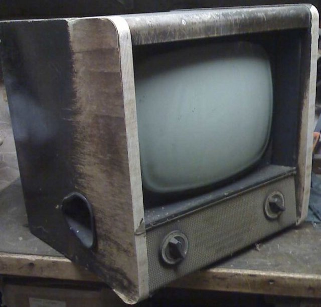
Ekco T311 1957 17" TV & Radio.
To make the restoration more difficult I decided to do it in front of the world by adding the work in progress onto a huge vintage radio Internet forum; I would either come out of this looking good or stupid for sticking my neck out if I failed but I intended to do my absolute best.
To say my working environment was bad would be an understatement as I started the restoration in November 2010 leading to the worst ever winter recorded in the UK. The garage and workshop were permanently frozen and both were black holes; most days the windows inside the workshop were covered in ice forcing me to do most of the work in our kitchen on a short bit of work surface between the sink and wall units. This meant constant frustration having to clear away for mealtimes etc. The tumble drier and washing machine provided entertainment through noise and vibration as they were in constant use. Just driving to obtain materials was terrible with frozen roads and the council also ran out of grit and salt. Gloomy and miserable about sums it up.
The first problem was were to start as the set was so bad. It was obvious the chassis and CRT (Tube) had to be removed together with everything else attached to the cabinet. Many digital pictures were taken and detailed sketches and notes made as each part was removed; this was most important as the least ambiguity would cause a great deal of difficulty later when everything needed re-installing. The CRT was gently cleaned by brushing removing years of dust and dirt then carried into our spare bedroom for safe storage; these CRT's (tubes) are extremely dangerous and can implode if knocked; people have been killed by CRT's being damaged and this is why there is always a toughened safety screen in front of them in the cabinet.

Severe delamination.
Finally the cabinet was stripped bare and I was terrified of introducing woodworm into our bungalow so it was treated. Looking at the bare cabinet I thought what the heck have I taken on; surely this cabinet is beyond repair and it would be much easier to make a brand new cabinet? A brand new cabinet was deemed plan “B”.
I could simply remove strips of outer veneer by gently pulling; the finish was either completely missing or in terrible condition. My first thought was to remove the outer face of each complete side to a depth of 1/4” then add a layer of ply and veneer over? The front of the cabinet gave the impression that the two sides were very thick plywood? It was difficult to see the inside of the cabinet even with both strip lights switched on in the garage. Eventually I realized the side panels were only thin plywood with a thick plywood frame to the front and top edges. The solid hardwood frame members were riddled with woodworm and a number of the joints had parted. I think at this point the cabinet would have been rejected by a skip.
I had bought a full sheet of moisture resistant 6mm MDF and a piece of this was placed onto the bench then the cabinet placed side down on top of the MDF; the cabinet was carefully drawn around using a sharp pencil. This was repeated for the other cabinet side ensuring I didn't miss drawing around the cut out for the side controls at one side. Both pieces of MDF were then very carefully cut to the pencil line using the big Startrite band-saw; time was taken to get this perfect as these two pieces would be the templates for cutting the new side panels. I could have used both these as the actual side panels but what would happen if I messed up? I decided to retain these as templates affording a back up. The templates were clearly marked in pencil to identify which side they were.

Entire cabinet side removed.
After double checking and checking again no detail had been missed on the templates the old cabinet sides could be removed. After a lot of thought A jigsaw was carefully used to cut out the bulk of the side with the opening. There was now no option of going back as I was committed. The remaining section was carefully removed with pliers and a wood chisel. Only now did the extent of the woodworm damage become known and it was bad. Much of the hardwood frame was nothing more than dust as was the core of the plywood.

Close up of woodworm damage.
Not wanting to lose the integrity of the cabinet having it collapse on me I decided to replace one side panel and framework before starting on the second side panel. At this point whilst looking at the original bland treacle coloured finish which had been applied over the original plywood I wondered if I could improve on this by introducing some decent veneers? What about a nice inlaid panel with stringing and cross-banding?
Surfing eBay for a few hours there was a selection of really nice Burr Walnut veneers that would have looked beautiful for the main inlaid panels but was very expensive and only available in small sizes. Eventually I noticed Sapele Pommele in long wide sheets at a very fair price; I had never heard of this veneer before but the figure was striking so I ordered two lengths.
Whilst waiting for the veneer I made ready the cabinet; the remains of the original side panel was removed and new hardwood frame members added. 2KG of Hide glue was ordered and a new veneering hammer made as the new veneer would be laid using the hammer method. The stringing was to be home made but perhaps banding would be a better description as this was laid up like plywood comprising of two inner layers of dark veneer and outer layers of light coloured veneer; a cutting jig and cutting gauge was made and the individual strings accurately cut out allowing plenty width for later trimming once glued in. With the veneer now to hand veneering could commence; the inside of each panel was veneered using common Sapele I had in stock but the outer face of each panel took considerable effort adding the main centre panel and Sapele cross banding. The thickness of the stringing was 0.082” and the smallest router bit diameter I could find on sale was 0.125” so why not make my own router bit out of a length of 1/4” dia silver steel?
I had never seen this done before but it worked a treat and the stringing was glued in; for the curved corners a pair of wooden moulds had been made to sandwich the stringing veneers so once cut out these didn't put up a fight and went home quite easily. When dry the stringing was hand scraped flush using a freshly sharpened cabinet scraper; at first scraping made the stringing look terrible but as it came down flush it proved to be perfect.
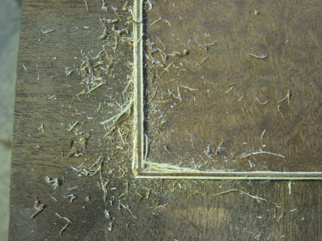
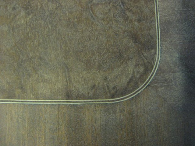
Scraping stringing sure looks rough until brought down flush.
Now having two brand new sides they needed attaching. Normally I like to use hot hide glue on cabinets but given the total length of the glue joint around the edge of each panel the hide glue would gel much too quickly so I dare not risk taking the chance and opted for waterproof woodworking adhesive to give a longer open time for positioning and clamping. All the clamps were made ready as were many packing pieces to prevent damage. I found attaching the first side panel to be stressful in getting it perfectly aligned whilst clamping and I applied plenty of adhesive as I didn't want a dry joint; excess was removed using a damp cloth.
What a relief it was to remove all the clamps from the first side to find it perfectly attached; the second side was attached using the same technique. This was a huge part of the restoration out of the way and over the next few weeks the remainder of the veneering was carried out together with more new framework being added; two bottom framework members were replaced in solid oak

New oak base section glued in.
I've done hammer veneering previously but always found it to be difficult until I found the “You tube” below video and copied the technique making this veneering job a great deal easier.
http://www.youtube.com/watch?v=awIBy11kMA8

Top veneered awaiting addition of stringing.
Once the veneers had been trimmed to size they were hand scraped then a thin coat of Raw Linseed Oil applied by cloth and allowed to completely dry. This really does make the colour jump out the the Pommele looked fabulous. French polishing followed; many brush coats of shellac was applied and it went on rough but the idea was to build up a good thickness to allow flatting without cutting through to bare veneer. Once a good thickness had been built up it was flatted using abrasive paper and Talcum Powder as lubricant. The talc prevents the abrasive paper from becoming coated and a sheet of abrasive paper lasts a long time. Care is needed to completely remove all traces of talc before adding more shellac or the talc will show up pure white; an artists brush is very useful for removing talc from corners. Once the brush coats had been applied and flatted the French polishing was finished using a traditional French Polishing Rubber.

Flatting using talcum powder as lubricant.
I new piece of 6mm laminated glass was bought and this would be the safety screen. The cabinet transformation looked stunning and I took it along to put on display at the Vintage radio meeting in Golborne where it was much admired. All during this work the weather was freezing and I detested it with a passion but I simply would not quit. Each day I would do a bit more work and after each session I would write up the notes on the forum where members began logging on every day just read the updates; it turned into a restoration version of “The Archers”. The weather robbed me of a lot of the pleasure and at times it was very hard work just to make a start each day but the weather wasn't going to beat me; no way.

What a joy it was to reach this stage.
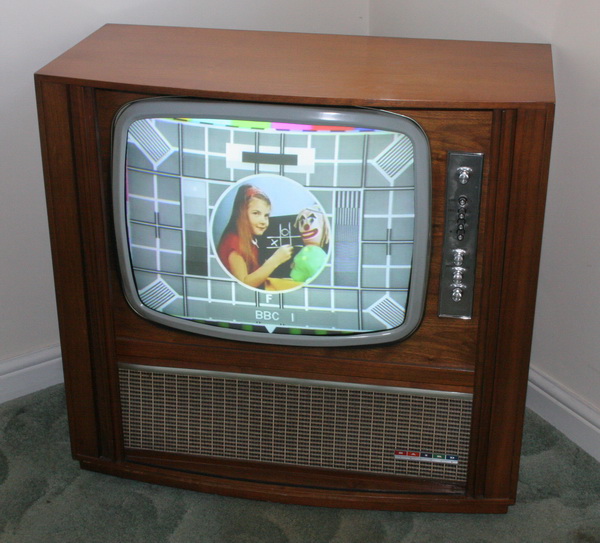
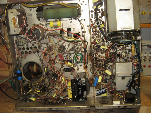
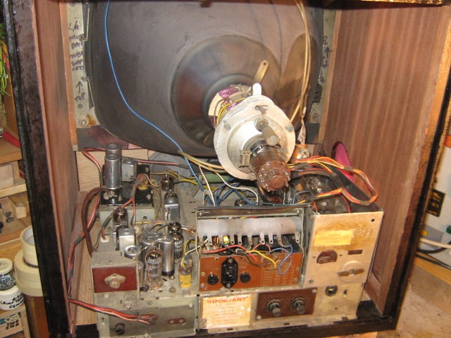
I didn't receive any help whatsoever all during the cabinet part of the restoration other than masses of encouragement from forum members which I was most grateful for. However the dreaded day finally arrived as I had to make a decision regarding the chassis restoration. Now I had access to the best TV experts in the world on the forum and many had actually worked on these sets when they were new. I put my hand up and declared I was a total novice at this kind of work so please would forum members treat me as such and lead me by the hand whilst I attempted to restore this wreck of a chassis. It wasn't long before I was shorting 16,000 volts from the rectifier to chassis using an insulated screwdriver. As I did this I noticed a strange smell in the air as a reaction from the spark. The line output transformer (LOPT) was burned out but a forum member very kindly posted a replacement to me totally free of charge as did other forum members with other needed spares. I used an air line to gently blow most of the dirt and debris from the chassis and I also made a wooden stand to hold the CRT safely on the bench together with the loudspeaker; I didn't want to come into contact with 16,000 volts so everything I did I did with utmost care. At the first switch on it blew the 3A fuse. This indicated heavy current drain and perhaps a direct short? After blowing more 3A fuses and not locating the fault I thought it time for the fault to make itself known so popped a 13A fuse into the plug. The loud bang and blue flash found the faulty mains capacitor which was easily changed then I could power the chassis using a 3A fuse and work through it. It was a truly amazing moment when I saw “First light” this is when a CRT (tube) lights up for the first time in many years. The forum members were absolutely brilliant and took me as a novice whilst reading their daily forum posts to getting this TV into full working order. I was merely a robot working to their commands but of course I had to correctly apply the commands. What a huge learning curve this restoration proved to be and I was overjoyed with the final result. I bought an Aurora standards converter and used this to bring up the test card as can be seen in the picture. The quality of all the pictures could be better but please remember I was working in a cold black hole throughout the restoration.
For the full story please visit the websites through the links below. At least I didn't make a fool of myself after all.
Kind regards, Col.
http://www.vintage-radio.net/forum/show ... hp?t=62371
http://www.vintage-radio.net/forum/show ... hp?t=67298
Here's the story of a cabinet restoration where the guy was too stupid to quit. I had never been interested in restoring a vintage TV and should have walked away from this one. I've restored many vintage radios over the last ten years adopting this as an hobby when I retired. I'm completely self taught in cabinetwork and electronics.
I hated woodwork at school and was bottom of the school in woodworking when I left school in 1962 aged 15; I also detested the bully of a woodwork teacher. I married my wonderful wife Bronwyn in 1976 and desperation due to lack of money forced me into woodworking due to necessary house repairs. Since those long ago days I've steadily improved and hope the following story whilst different to the normal will prove of interest.
Being a member of The British Vintage Wireless Society I noticed a really rough looking TV in a copy of the societies Bulletin and made enquiries as I thought the cabinet would make a lovely restoration project even though I hadn't a clue about the workings of a TV chassis. This particular set was not available but I was offered a selection of sets through a vintage radio forum and I chose the roughest of the lot. This was an Ekco T311 of 1957 vintage; table model with 17” screen and was also a radio.
Boy it was rough; riddled with woodworm and a badly de-laminating cabinet; the safety screen was missing and the chassis was in the same terrible condition buried under a lot of dirt and debris. I knew I wouldn't stand a chance of restoring the chassis but I was interested to see what I could make of the cabinet. A set in this condition is described as a “basket case” and they certainly didn't come much worse than this one.
The only thing in my favour as I looked at it sitting on the bench was that whatever I did to it I surely couldn't make it any worse. It was in dire need of a lot of loving care and was my biggest restoration challenge to date.

Ekco T311 1957 17" TV & Radio.
To make the restoration more difficult I decided to do it in front of the world by adding the work in progress onto a huge vintage radio Internet forum; I would either come out of this looking good or stupid for sticking my neck out if I failed but I intended to do my absolute best.
To say my working environment was bad would be an understatement as I started the restoration in November 2010 leading to the worst ever winter recorded in the UK. The garage and workshop were permanently frozen and both were black holes; most days the windows inside the workshop were covered in ice forcing me to do most of the work in our kitchen on a short bit of work surface between the sink and wall units. This meant constant frustration having to clear away for mealtimes etc. The tumble drier and washing machine provided entertainment through noise and vibration as they were in constant use. Just driving to obtain materials was terrible with frozen roads and the council also ran out of grit and salt. Gloomy and miserable about sums it up.
The first problem was were to start as the set was so bad. It was obvious the chassis and CRT (Tube) had to be removed together with everything else attached to the cabinet. Many digital pictures were taken and detailed sketches and notes made as each part was removed; this was most important as the least ambiguity would cause a great deal of difficulty later when everything needed re-installing. The CRT was gently cleaned by brushing removing years of dust and dirt then carried into our spare bedroom for safe storage; these CRT's (tubes) are extremely dangerous and can implode if knocked; people have been killed by CRT's being damaged and this is why there is always a toughened safety screen in front of them in the cabinet.

Severe delamination.
Finally the cabinet was stripped bare and I was terrified of introducing woodworm into our bungalow so it was treated. Looking at the bare cabinet I thought what the heck have I taken on; surely this cabinet is beyond repair and it would be much easier to make a brand new cabinet? A brand new cabinet was deemed plan “B”.
I could simply remove strips of outer veneer by gently pulling; the finish was either completely missing or in terrible condition. My first thought was to remove the outer face of each complete side to a depth of 1/4” then add a layer of ply and veneer over? The front of the cabinet gave the impression that the two sides were very thick plywood? It was difficult to see the inside of the cabinet even with both strip lights switched on in the garage. Eventually I realized the side panels were only thin plywood with a thick plywood frame to the front and top edges. The solid hardwood frame members were riddled with woodworm and a number of the joints had parted. I think at this point the cabinet would have been rejected by a skip.
I had bought a full sheet of moisture resistant 6mm MDF and a piece of this was placed onto the bench then the cabinet placed side down on top of the MDF; the cabinet was carefully drawn around using a sharp pencil. This was repeated for the other cabinet side ensuring I didn't miss drawing around the cut out for the side controls at one side. Both pieces of MDF were then very carefully cut to the pencil line using the big Startrite band-saw; time was taken to get this perfect as these two pieces would be the templates for cutting the new side panels. I could have used both these as the actual side panels but what would happen if I messed up? I decided to retain these as templates affording a back up. The templates were clearly marked in pencil to identify which side they were.

Entire cabinet side removed.
After double checking and checking again no detail had been missed on the templates the old cabinet sides could be removed. After a lot of thought A jigsaw was carefully used to cut out the bulk of the side with the opening. There was now no option of going back as I was committed. The remaining section was carefully removed with pliers and a wood chisel. Only now did the extent of the woodworm damage become known and it was bad. Much of the hardwood frame was nothing more than dust as was the core of the plywood.

Close up of woodworm damage.
Not wanting to lose the integrity of the cabinet having it collapse on me I decided to replace one side panel and framework before starting on the second side panel. At this point whilst looking at the original bland treacle coloured finish which had been applied over the original plywood I wondered if I could improve on this by introducing some decent veneers? What about a nice inlaid panel with stringing and cross-banding?
Surfing eBay for a few hours there was a selection of really nice Burr Walnut veneers that would have looked beautiful for the main inlaid panels but was very expensive and only available in small sizes. Eventually I noticed Sapele Pommele in long wide sheets at a very fair price; I had never heard of this veneer before but the figure was striking so I ordered two lengths.
Whilst waiting for the veneer I made ready the cabinet; the remains of the original side panel was removed and new hardwood frame members added. 2KG of Hide glue was ordered and a new veneering hammer made as the new veneer would be laid using the hammer method. The stringing was to be home made but perhaps banding would be a better description as this was laid up like plywood comprising of two inner layers of dark veneer and outer layers of light coloured veneer; a cutting jig and cutting gauge was made and the individual strings accurately cut out allowing plenty width for later trimming once glued in. With the veneer now to hand veneering could commence; the inside of each panel was veneered using common Sapele I had in stock but the outer face of each panel took considerable effort adding the main centre panel and Sapele cross banding. The thickness of the stringing was 0.082” and the smallest router bit diameter I could find on sale was 0.125” so why not make my own router bit out of a length of 1/4” dia silver steel?
I had never seen this done before but it worked a treat and the stringing was glued in; for the curved corners a pair of wooden moulds had been made to sandwich the stringing veneers so once cut out these didn't put up a fight and went home quite easily. When dry the stringing was hand scraped flush using a freshly sharpened cabinet scraper; at first scraping made the stringing look terrible but as it came down flush it proved to be perfect.


Scraping stringing sure looks rough until brought down flush.
Now having two brand new sides they needed attaching. Normally I like to use hot hide glue on cabinets but given the total length of the glue joint around the edge of each panel the hide glue would gel much too quickly so I dare not risk taking the chance and opted for waterproof woodworking adhesive to give a longer open time for positioning and clamping. All the clamps were made ready as were many packing pieces to prevent damage. I found attaching the first side panel to be stressful in getting it perfectly aligned whilst clamping and I applied plenty of adhesive as I didn't want a dry joint; excess was removed using a damp cloth.
What a relief it was to remove all the clamps from the first side to find it perfectly attached; the second side was attached using the same technique. This was a huge part of the restoration out of the way and over the next few weeks the remainder of the veneering was carried out together with more new framework being added; two bottom framework members were replaced in solid oak

New oak base section glued in.
I've done hammer veneering previously but always found it to be difficult until I found the “You tube” below video and copied the technique making this veneering job a great deal easier.
http://www.youtube.com/watch?v=awIBy11kMA8

Top veneered awaiting addition of stringing.
Once the veneers had been trimmed to size they were hand scraped then a thin coat of Raw Linseed Oil applied by cloth and allowed to completely dry. This really does make the colour jump out the the Pommele looked fabulous. French polishing followed; many brush coats of shellac was applied and it went on rough but the idea was to build up a good thickness to allow flatting without cutting through to bare veneer. Once a good thickness had been built up it was flatted using abrasive paper and Talcum Powder as lubricant. The talc prevents the abrasive paper from becoming coated and a sheet of abrasive paper lasts a long time. Care is needed to completely remove all traces of talc before adding more shellac or the talc will show up pure white; an artists brush is very useful for removing talc from corners. Once the brush coats had been applied and flatted the French polishing was finished using a traditional French Polishing Rubber.

Flatting using talcum powder as lubricant.
I new piece of 6mm laminated glass was bought and this would be the safety screen. The cabinet transformation looked stunning and I took it along to put on display at the Vintage radio meeting in Golborne where it was much admired. All during this work the weather was freezing and I detested it with a passion but I simply would not quit. Each day I would do a bit more work and after each session I would write up the notes on the forum where members began logging on every day just read the updates; it turned into a restoration version of “The Archers”. The weather robbed me of a lot of the pleasure and at times it was very hard work just to make a start each day but the weather wasn't going to beat me; no way.

What a joy it was to reach this stage.
I didn't receive any help whatsoever all during the cabinet part of the restoration other than masses of encouragement from forum members which I was most grateful for. However the dreaded day finally arrived as I had to make a decision regarding the chassis restoration. Now I had access to the best TV experts in the world on the forum and many had actually worked on these sets when they were new. I put my hand up and declared I was a total novice at this kind of work so please would forum members treat me as such and lead me by the hand whilst I attempted to restore this wreck of a chassis. It wasn't long before I was shorting 16,000 volts from the rectifier to chassis using an insulated screwdriver. As I did this I noticed a strange smell in the air as a reaction from the spark. The line output transformer (LOPT) was burned out but a forum member very kindly posted a replacement to me totally free of charge as did other forum members with other needed spares. I used an air line to gently blow most of the dirt and debris from the chassis and I also made a wooden stand to hold the CRT safely on the bench together with the loudspeaker; I didn't want to come into contact with 16,000 volts so everything I did I did with utmost care. At the first switch on it blew the 3A fuse. This indicated heavy current drain and perhaps a direct short? After blowing more 3A fuses and not locating the fault I thought it time for the fault to make itself known so popped a 13A fuse into the plug. The loud bang and blue flash found the faulty mains capacitor which was easily changed then I could power the chassis using a 3A fuse and work through it. It was a truly amazing moment when I saw “First light” this is when a CRT (tube) lights up for the first time in many years. The forum members were absolutely brilliant and took me as a novice whilst reading their daily forum posts to getting this TV into full working order. I was merely a robot working to their commands but of course I had to correctly apply the commands. What a huge learning curve this restoration proved to be and I was overjoyed with the final result. I bought an Aurora standards converter and used this to bring up the test card as can be seen in the picture. The quality of all the pictures could be better but please remember I was working in a cold black hole throughout the restoration.
For the full story please visit the websites through the links below. At least I didn't make a fool of myself after all.
Kind regards, Col.
http://www.vintage-radio.net/forum/show ... hp?t=62371
http://www.vintage-radio.net/forum/show ... hp?t=67298
Attachments
-
 Ekco T311 (1).jpg49.5 KB
 -
 Delamination..jpg54.1 KB
 -
 Entire side removed..jpg44 KB
 -
 Close up of woodworm damage.jpg42.9 KB
 -
 New base section glued in..jpg56.3 KB
 -
 Scraping sure looks rough..jpg76.6 KB
 -
 Scraped flush and looking better..jpg60.2 KB
 -
 Top now veneered.jpg54.6 KB
 -
 Flatting under way..jpg58.8 KB
 -
 What a joy..jpg81.9 KB


