Startrite Bantam (drill) refurb

UKworkshop.co.uk

Help Support UKworkshop.co.uk:

This site may earn a commission from merchant affiliate links, including eBay, Amazon, and others.

samhay

Established Member
Joined
10 Aug 2017
Messages
325
Reaction score
37
Location
Peak District
I picked up a Startrite Bantam bench pillar drill quite cheaply last year and have been meaning to tidy it up a bit. The time has come. At a minimum I need to replace the wiring, which is not in a good way and take the motor apart for a clean as it is full of crud. I expect it will largely have to come to pieces to get the switch out and new wiring in, so will probably look at replacing bearings while I'm at it. The pillar could also do with a clean to make it somewhat easier to move the head up and down.

Much of this is new to me, so would appreciate some help at various stages. As I am taking pictures in the hope that this will help me get it back together, I figured I would share the journey.

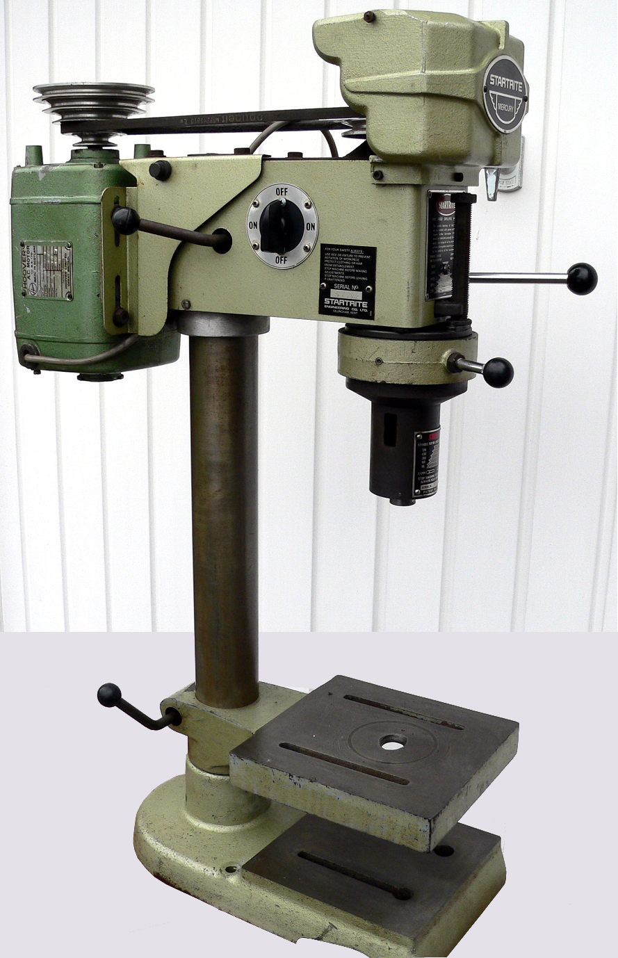
The Bantam is the Mercury's little brother. Same head on a shorter pillar and no table:
More info here: http://www.lathes.co.uk/startrite-drills/

This is mine:
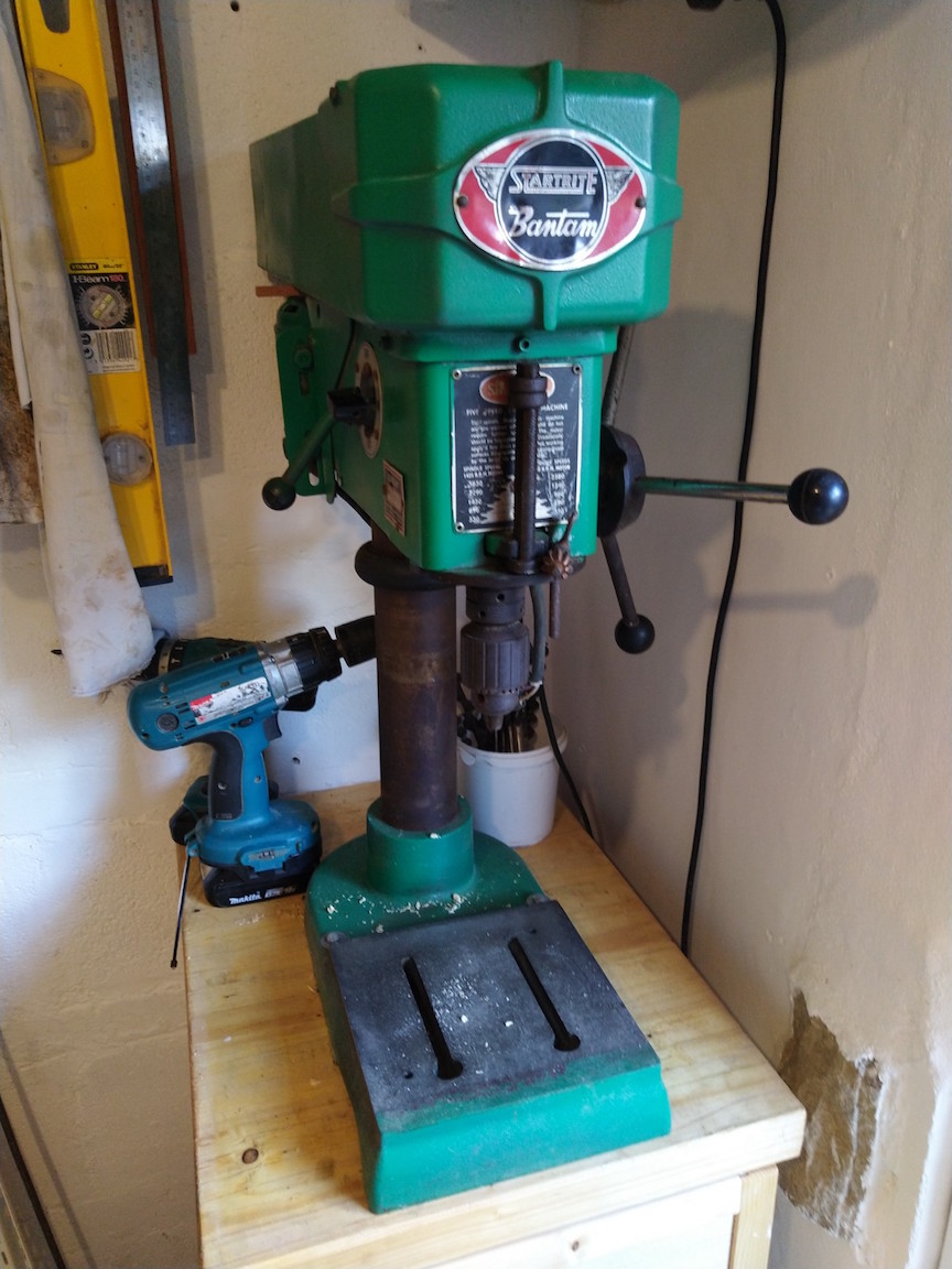
IMG_20200706_165841.jpg

The paint job is neither original, nor expertly executed, but it will probably do for the moment.
The motor appears to be original, a single phase 1/2 HP Ranco:
IMG_20200706_173008.jpg

At some point (I assume) someone has added a new plug. It is not grounded and I found the connector block and a couple of unconnected wires wrapped in masking tape floating inside the body. I have since added the insulation tape while pondering its fate. It works, or at least did before I started taking it apart, but I think I can do better.
IMG_20200706_172647.jpg


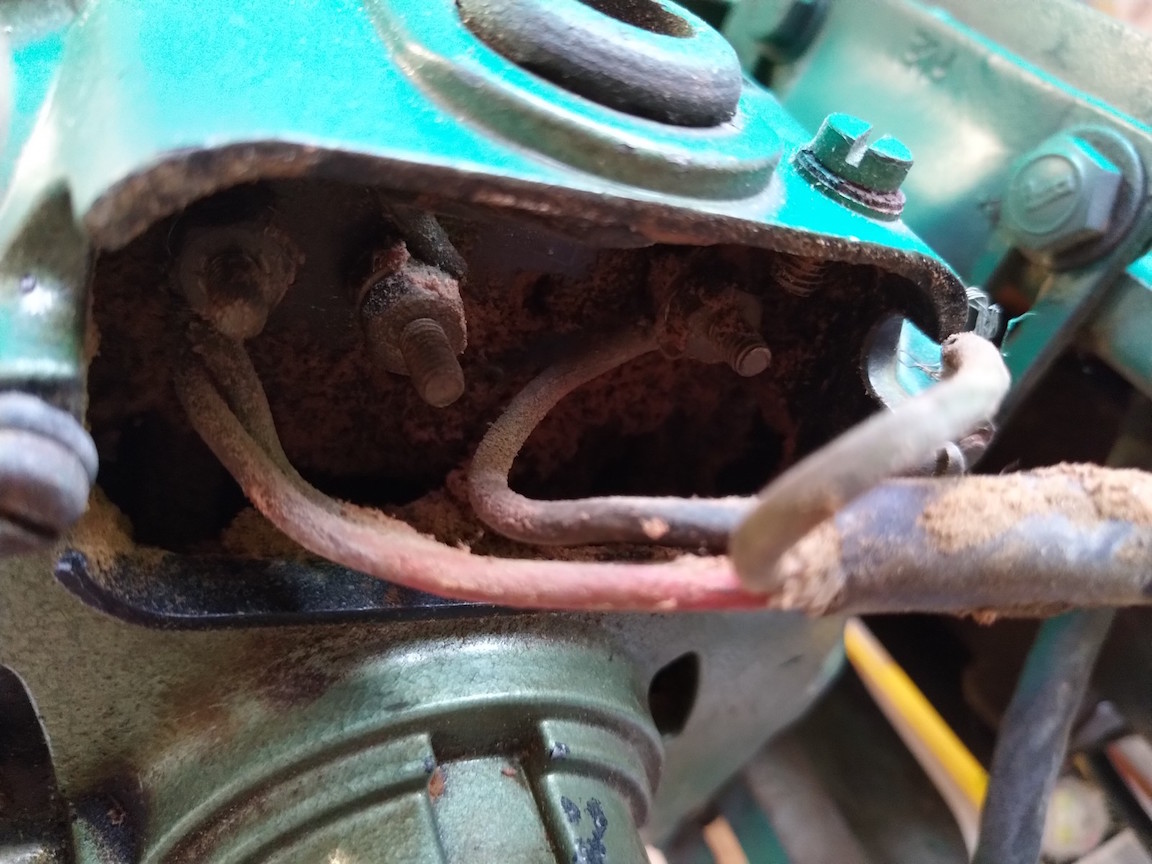
I haven't got the switch out yet, but this is what I found under the motor plate. I expect it will make sense to some of you?
IMG_20200706_170435.jpg

IMG_20200706_173114.jpg


Questions for now. Don't expect there will be much argument against a rewire. I haven't got to the switch yet, but I don't see that being in much better shape. The switch allows the drill direction to reverse, which I'd like to preserve. Considering adding an NVR switch, which should work ok if put before the existing switch?
Need to work out how best to earth the drill - is the earth connection on the motor sufficient?
Also, does anyone know what size Allen key I need for the grub screws on the pulleys?

Thanks, and more soon.
 

Attachments

  • IMG_20200706_165841.jpg
    IMG_20200706_165841.jpg
    202.9 KB
  • IMG_20200706_173008.jpg
    IMG_20200706_173008.jpg
    201.2 KB
  • IMG_20200706_172647.jpg
    IMG_20200706_172647.jpg
    225.4 KB
  • IMG_20200706_170435.jpg
    IMG_20200706_170435.jpg
    306.2 KB
  • IMG_20200706_173114.jpg
    IMG_20200706_173114.jpg
    208.7 KB
Hi.
There’s a few drill refurb posts on here. Use the search facility to see if someone has the same drill.
Yes to the rewire and using an NVR.
Earthing the motor and/or the drill body, (possibly somewhere on the switch?) will suffice.
Cleaning the shaft, depending on condition, citric acid solution or a commercial de-rust or degreaser. Wire wool, light wire brushing or a fine wet and dry. If it’s not too bad citric acid and a Brillo pad work wonders.
 
I've found a few Mercury refurbs on here, but nothing about the wiring. Many have 3 phase motors anyway and I'm curious about the motor wiring. What's the unused connection for?

I managed to get the grub screws out of the pulleys by filing down an allen key. Of course the pulleys are still stuck, so will have to decide whether it's worth trying to pull them off or not. There is a bit of vertical play in the motor shaft but the bearings don't seem to be in terrible condition.
 
Before you get to trying pullers / heat on the pulleys make a very careful check for second grub screws, I have seen this on occasions. Then first stage is to try heat, easiest to try paint stripping air gun or plumbing gas torch as first try. If you resort to pullers, take great care if the pulleys are aluminium , it is possible to break them !
 
I managed to pull out 2 grub screws from the front pulley and one longer one from the rear.
Can't see anything else, but it's not easy to see what's at the bottom of the screw hole.
I was planning on taking a heat gun to the pulleys and will proceed with care. The front pully has already lost its top pulley at some point in the past, so have plenty to remind me to take it slow.
 
samhay":1vq2dcp8 said:
I've found a few Mercury refurbs on here, but nothing about the wiring. Many have 3 phase motors anyway and I'm curious about the motor wiring. What's the unused connection for?

I managed to get the grub screws out of the pulleys by filing down an allen key. Of course the pulleys are still stuck, so will have to decide whether it's worth trying to pull them off or not. There is a bit of vertical play in the motor shaft but the bearings don't seem to be in terrible condition.
The wiring diagram on the motor plate isn’t especially helpful, and I haven’t found much online yet. There ought to be a starting method of some sort, usually a capacitor. Show some more pics when you pull the motor apart.

Earth to motor frame should be fine, and do another one from the NVR switch. Scrape away the paint and use a shakeproof (spiky) washer.
 
More progress today. Wiring is starting to make sense as it appears (well I'm guessing) to be standardised so the same switch and motor parts for singe and 3 phase motors.
Not sure how much use of interest this will be, but is a good way to document what I'm doing so I hopefully can get everything back together again.

The switch is a 3 pole 4 position rotary switch. More on this later. I will need to get the multimeter out to work out which poles are switched in each throw, but in essence all it needs to do here is invert the 2 supply wires. The earth bypasses the switch and is sent straight to the motor for grounding.
IMG_20200707_180444.jpg


The 3 supply wires are connected to the motor plate as shown in one of yesterday's photos. 2 are (were) connected to the right lug and 1 to the left. The middle lug is connected to the motor winding but not the supply from the switch.
IMG_20200707_173936.jpg


After flipping this little board over and cleaning some of the crud out I found a contact switch. You will notice the board is designed for a second one (counting the empty holes), but only half is connected and there seems to be options to add a second contact for each switch. I guess this would be used for a 3 phase motor?
IMG_20200707_173920.jpg
IMG_20200707_173903.jpg
IMG_20200707_180615.jpg


You will also notice there are 2 sets of connections to the motor windings and no start capacitor.
Edit - go this bit wrong. Let's try again. This is some sort of centrifugal switch, which contacts the contact switch in the above photos and I assume this is why there is some lateral movement in the shaft. Once the motor spins up, the rotor rises and disconnects the contact switch, which is closed by the weight of the rotor when powered off - this photo shows the motor upside down.
IMG_20200707_180517.jpg
 

Attachments

  • IMG_20200707_180444.jpg
    IMG_20200707_180444.jpg
    263.1 KB
  • IMG_20200707_173920.jpg
    IMG_20200707_173920.jpg
    329.6 KB
  • IMG_20200707_173903.jpg
    IMG_20200707_173903.jpg
    271.9 KB
  • IMG_20200707_180517.jpg
    IMG_20200707_180517.jpg
    226.9 KB
  • IMG_20200707_180615.jpg
    IMG_20200707_180615.jpg
    273.3 KB
  • IMG_20200707_173936.jpg
    IMG_20200707_173936.jpg
    373.5 KB
And here is a wiring diagram. Not sure if the second wire from the rotary switch to the bottom lug is needed, but may be depending on how the rotary switch works. That's the next job.

wiring.jpeg


I'm pretty sure the contact switch is normally open, but it's at the bottom of the motor and with the weight of the rotor on it it is probably closed when powered off. If the rotor moves up* once spinning, the switch will open and disconnect the auxiliary (starter) winding.
It's a miracle this still worked as it was packed full of crud.

*not the rotor itself, but the black disc in the centrifugal switch. Must give it a prod tomorrow to confirm.
 

Attachments

  • wiring.jpeg
    wiring.jpeg
    32.9 KB
Looks like a resistance start motor. The run winding has low resistance and high reactance, so its current is heavily phase-shifted. The start winding is the opposite, so its current is nearly in phase.

This phase difference is enough to provide a starting torque, or rotation, and once up to speed the centrifugal switch disconnects the start winding.

Next move would be to ohm the windings and find out which is which. Then ohm out the switch.

For a particular direction, line needs to go to one end of the run winding, and to the centrifugal switch. The other side of the switch goes to one end of the start winding. Neutral goes to the junction of the two windings.

Reversal is usually done by swapping the start winding connections.

You need to get busy with a piece of paper, tracing out how all that is achieved based on your study of the motor windings and switch, but you appear to be more than capable. The above is mainly for others who might come across this thread. (hammer)
 
Yes, this looks like a resitance start motor. For those of you following along at home, this may be helpful if you are not familar with these:
https://www.allaboutcircuits.com/textbook/alternating-current/chpt-13/single-phase-induction-motors/
The auxilary winding should be signficanly lower resistance, so can tease that out with multimeter.
As the black wire appears to be only connected when the contact switch is closed (motor off), this likely goes to the end of the auxillary winding and the yellow wires goes to the end of the main winding. As the red and blue wires are connected together, these must go to the other end of the windings. Will need to check the resitances to work out which is which. However, this is all academic as I am not planning on doing anything with this end of the wiring.
 
samhay":2ylj0uhb said:
The auxilary winding should be signficanly lower resistance, so can tease that out with multimeter.
*higher resistance, I would think.

I wasn’t sure if the rotary switch was OFF-FORWARD-OFF-REVERSE, or just two ONs and two OFFs. I haven’t seen a reversible pillar drill, but it might come in handy for using a wire wheel.
 
OK, I stand corrected and have learnt something this morning. The auxillary winding will have higher resitance and lower inductance.

The rotary switch is forward - off - reverse - off. I don't have a handy photo, but this shows it nicely:
img12.jpg
 
Having now spent some time with a multimeter, it seems the rotary switch is in fact on-off-on-off.
Must have misremembered or never tried reverse. One of the brochures mentions a reverse switch is an option, but I can't see how this one could be wired to do this - it doesn't have enough terminals and would need to be a double throw (2 outputs per pole) type switch instead.

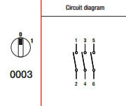
It works as 3 ganged SPSTs like this:
on-off-3-pole.jpg


The motor behaved as expected.
The black wire is connected to the auxiliary winding with a resistance of ~9 Ω.
The white/yellow wire is connected to the main winding with a resistance of ~4 Ω.
I have not disconnected the red and green wires to check which goes to which winding, but these must go to the other ends and are connected at the board.

As the rotary switch won't do anything the NVR does, I think I'll remove it. It looks pretty cool with the base plate, but would be redundant.
 
I can’t see why they would bother fitting a 3-pole/4 position switch where a 2-pole/2 position switch is needed. Before the days of bean counters?!

Note for beginners - no, you don’t put the earth through the switch. It should be continuous and always connected.

Why not put the rotary switch before the NVR? It would preserve the look (and not get lost), and act as secondary isolation when you’re changing speed/bits.
 
off-on-off-on switches seem common on drills from that era for some reason and fitting a 3 pole as standard means only stocking one switch in production for both 3 phase and single phase.
 
Yes, using the same part for both 1 and 3 phase motors makes sense. I assume the on-off-on-off made sense for some reason. I could dismantle it to see if there is an obvious answer in how they are made, but will leave that until if/when I decide I don't need it any more.

If I put the rotary switch before (supply side) the NVR, it will trip the NVR every time you use it as it will break the supply connections. Once the NVR arrives - probably today - I will work out where to situate it. If there is room for both switches, I may keep them and/or will think about replacing the rotarty switch for a 3 postion forward -off-reverse type switch. Not sure it's worth the bother at the moment though as the drill is not rare or precious enough to try to keep mint.
 
Finished wiring this up.
Guessed the motor wiring correctly, so spun up in the correct direction (sorry for the poor photo, but forgot to take one before bolting the motor back on and had to take this upside down):
IMG_20200722_133735.jpg

wiring2.jpeg


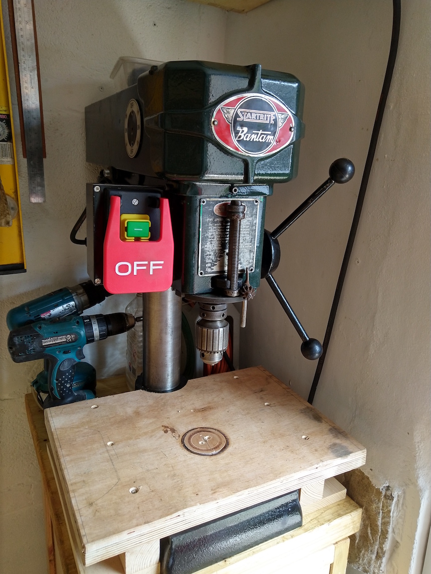
This is how I placed the new switch. Figured a panic switch would be helpful on those occasions when the drilled material gets away from you.
Didn't managed to replace any of the bearings as I couldn't get the pulleys off and the bearings in the quill seemed to be healthy - this is easier to deal with without stripping the drill if I change my mind in the future.
Cleaned up the column and it is now much easier to change the head height. Still an element of weight lifting required, but this was expected.
Couldn't get the chuck off to clean properly. Must get some wedges, but this can wait until another rainy day.
IMG_20200722_133555.jpg

IMG_20200722_133917.jpg
 

Attachments

  • IMG_20200722_133735.jpg
    IMG_20200722_133735.jpg
    200 KB
  • wiring2.jpeg
    wiring2.jpeg
    89.1 KB
  • IMG_20200722_133917.jpg
    IMG_20200722_133917.jpg
    337.6 KB
  • IMG_20200722_133555.jpg
    IMG_20200722_133555.jpg
    360.2 KB
Goodness me, that switch is ugly on that old drill! Should be nice and safe, though. Well done on the refurb.
 
“If I put the rotary switch before (supply side) the NVR, it will trip the NVR every time you use it as it will break the supply connections.”

Didn’t spot this - I meant keep the rotary switch on all the time, and use the NVR. Turn the rotary off for extra isolation.
 
Yes, the switch is a bit fugly, but the drill is neither particularly pretty or collectable.
I'm also prone to drilling things that are not clamped down. If I get sick of looking at it, I can also move/ rotate it to sort flat on the side, which is a little less intrusive.
The other switch would be redundant and there is not enough room for both on that side, so was an easy decision. May use it for something else one day.
 

Latest posts

Back
Top