Portable (bench-top) Workbench

UKworkshop.co.uk

Help Support UKworkshop.co.uk:

This site may earn a commission from merchant affiliate links, including eBay, Amazon, and others.

Dr Al

Established Member
Joined
11 May 2020
Messages
369
Reaction score
916
Location
Dursley, Gloucestershire
This project has been on my list for a while now, but I started the main body of work this weekend. The aim is to make a portable (ish) workbench that can be placed on top of my existing bench (or the dining table if necessary!) to give a raised work surface and a couple of different vices that can be used without being constrained to being in one fixed spot on my existing bench.

I've seen a few designs in various places; I might have got carried away with my design and also might have bitten off more than I can chew, but we'll see...
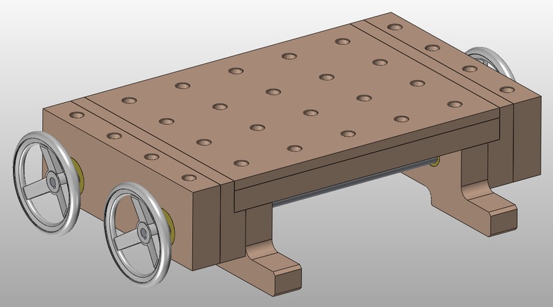
portableworkbench_model_1_800.jpg


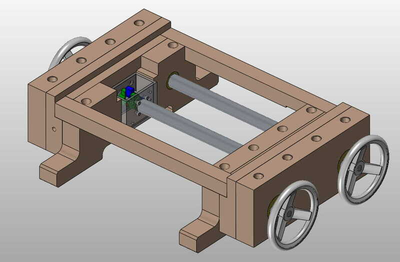
For a sense of scale, the total dimensions of the top surface (including the top of the vice jaws) will be 630 × 380 mm. The vice jaws are 50 mm thick. Including the feet (which stick out for ease of clamping down to another surface), the width is 530 mm. The total height is 166 mm. The dog holes are 20 mm diameter on a 96 mm pitch. The dog holes in the vice jaws will (like the ones on my existing bench) make for easy clamping of thin-ish stuff on the top.

The vice mechanisms will be based on M20 threaded rod; pretty much everything apart from the hand wheels and threaded rod will be made by me from the beech and some bits of brass & steel bar stock. I would have preferred to use M24 threaded rod, but I can get M20 threaded rod locally at a countryside store so I'm going with that for simplicity. I've also got some 30 mm OD, 5 mm wall thickness (and hence 20 mm ID) seamless mild steel tube and that's quite handy for the design given that I'm using 20 mm threaded rod.
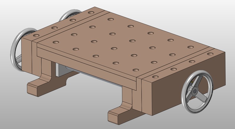
portableworkbench_model_2_800.jpg


I should probably say at this stage that I'm not even going to try to do this as a hand tools project: this is intended to make it easier to do hand tool based woodworking projects, but I'm going to use every tool I've got to make this! I'm also not planning to include any fancy joinery: just whatever will work and be straightforward. It's going to be fairly hefty and several parts will have bits of brass or steel going through them so there's not much chance of things wandering off. I haven't decided how the rails will be attached to the fixed jaws yet (apart from that they'll go into a cut-out), but it'll probably either be just glue or glue & dowels. The top will be screwed in place (probably with slotted holes in the rails and buttons into slots in the feet) so that it can be removed if required.

I'm making this partly as I think it'll be really useful to have around, but also partly because I think I'll enjoy making it. There's lots of different aspects to this project: machine woodworking (lots of that), some hand tool woodworking, a fair amount of metal turning, a bit of metal milling and some TIG welding. I enjoy all of those things, so from my point of view it should be a good project, regardless of the outcome!
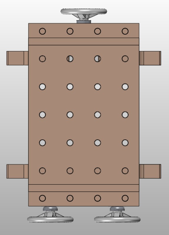
portableworkbench_model_3_800.jpg


The plan is to have two vices (with home-made quick-release mechanisms). The one at the top of the image above is a conventional vice, with a central screw and two slider bars made of 30 mm OD, 20 mm ID steel tube. Being raised above my normal bench will be handy for cross-cutting stock as the hand saw will have somewhere to go at the bottom of the cut. I'm wondering about adding a dowel into the right-hand side of the fixed jaw of the conventional vice (top-left of the image above) so if I'm a bit over eager with the hand saw at the end of the cut it'll hit the dowel rather than the workbench underneath - the dowel would be easily swapped out once it gets beaten up.

The vice at the bottom of the picture is a dual-screw "Moxon-style" vice with slots in the moving jaw to allow angled clamping. Assuming it works, this should allow me to clamp long workpieces vertically in the vice - up to 200 mm wide. It'll also cope with tapered workpieces thanks to the slotted bushes in the moving jaw.

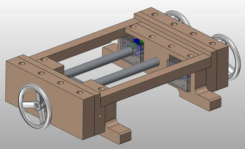
This picture shows what it would look like with the jaws open:
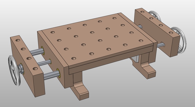
portableworkbench_model_4_800.jpg


This is a view of it with the top surface hidden: note that I've modelled the vice mechanisms as simple white boxes for now; I might update the model once I've made them and know the actual details a bit more accurately.
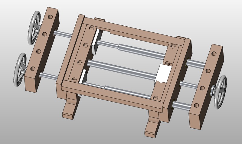
portableworkbench_model_5_800.jpg


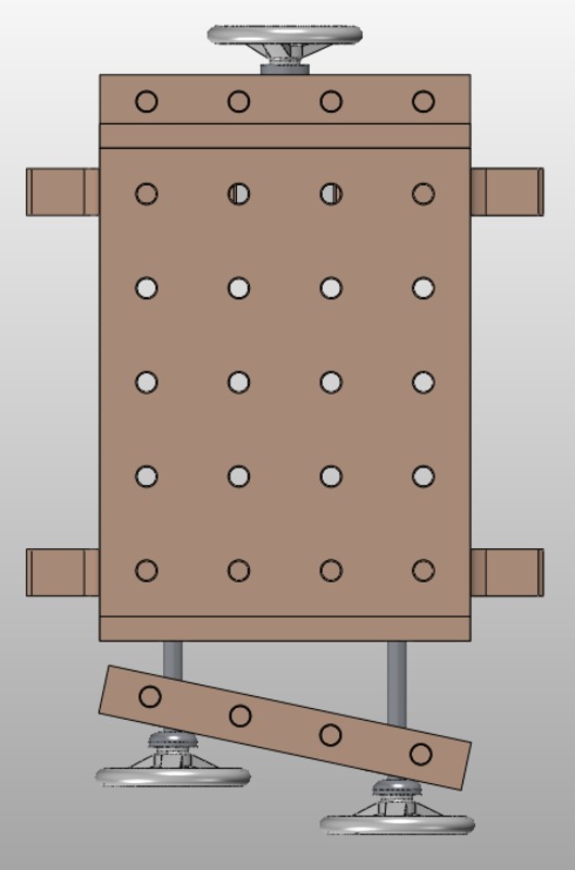
Here are a couple of views of the angled vice jaw (at somewhere near the maximum angle that will be possible with the slots as drawn):
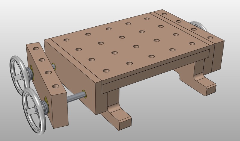
portableworkbench_model_6_800.jpg


portableworkbench_model_7_800.jpg


The source material is a 4 metre-ish long piece of beech that was about 150 mm × 50 mm or thereabouts in section (I didn't measure it before cutting it up, but some of the shortened lengths ended up 50 mm thick after planing, so it must have been a bit over that to start with). I cut it up into lengths, planed it (router sled for one side, thicknesser for the other) and measured all the bits that were left. I then updated the CAD model to suit!

I'd planned the top surface of the workbench to be 18 mm thick. I planed the four individual pieces to 18 mm thick, then edge jointed them. I didn't get that quite right and ended up taking another 2 mm off the thickness to get them flat and of a consistent thickness, so the top is now 16 mm thick. I think that should be fine though, the unsupported width (between the two side rails) is only 310 mm.
 
The first job I did on this (back in January) was to make a prototype of the vice mechanism. The mechanism is based on an idea from a youtube video by Neil Paskin. He didn't provide any dimensions or other details, so I had to work it out for myself (he has also made a plywood version and provided drawings for that, but I wanted to make a metal one). I figured it would be worth testing it out as I was sure it would need some tweaks.

vice_mechanism_prototype_1_800.jpg


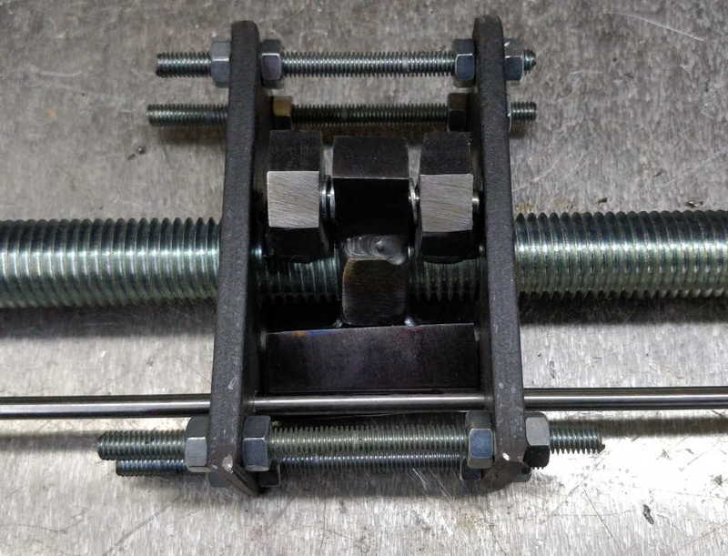
The photo above shows the prototype assembled. I learned quite a few things doing this - hopefully the next version won't need those washers spacing out the lock parts! The final version won't be held together by M6 threaded rod either; that was just for testing.

Here's another view with the lock piece removed:

vice_mechanism_prototype_2_800.jpg


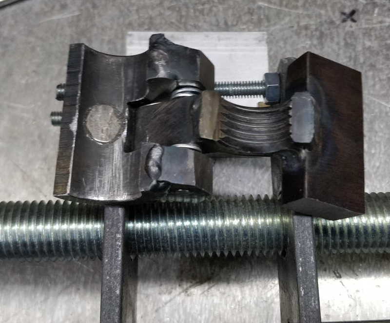
The threaded part of the mechanism is half of an M20 hex nut, with a big block of steel welded to it on each side. The one on the right-hand side of the photo here presses against the plates when tightening (or loosening) and stops the assembly from twisting. It also presses against the round bar you can see in the first photo and limits the clockwise movement of the mechanism (causing the vice to tighten).

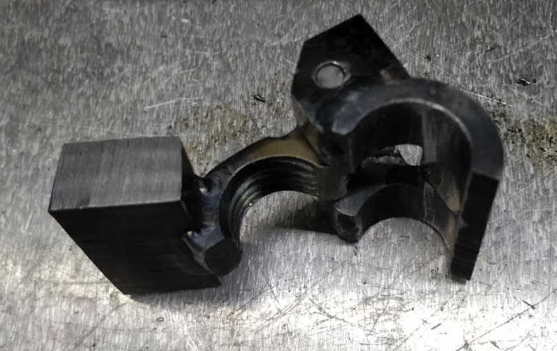
The other half of the lock mechanism is made from half of a bit of 30 mm OD, 20 mm ID tube. It's got a hole cut in it for a magnet and two bits of bar welded to it to act as half of a hinge.

vice_mechanism_prototype_3_800.jpg

vice_mechanism_prototype_4_800.jpg


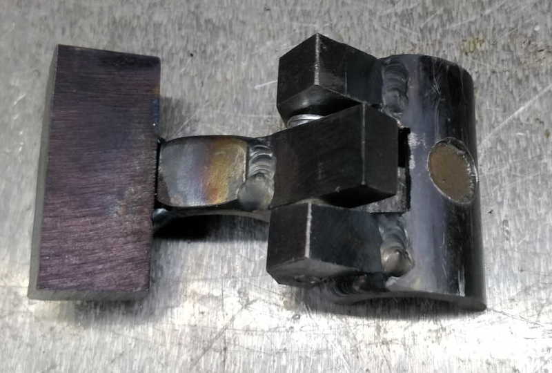
These photos show the lock part on its own. The other block welded to the nut (on the right-hand side of the nut on the last picture) serves two purposes. Firstly it provides the other part of the hinge. Secondly, it presses against the round bar when you turn the mechanism anticlockwise - this causes the nut to lift off the threaded rod, leaving only the tube half engaged (and held on with the magnet).

The result is a vice that you turn half-a-turn anticlockwise and it disengages allowing it to slide in and out freely, but you turn it half-a-turn clockwise and it engages and can be tightened.

Based on a few experiments with the prototype, it seems to work really well and I think it's going to be a lot nicer to use than the separate lever used as a quick release on my Record 52A.
 
I started by cutting the beech into lengths of roughly double-plus-a-bit what was needed for each component. The "double" was because there's two of each component type, the plus a bit was to try to allow for the snipe of my thicknesser. I didn't quite get that right and there's a little evidence of snipe on the ends of the outside face of the moving jaws, but I'll probably just round those ends off and it'll disappear (it's only about 7 mm into the ends of the pieces).

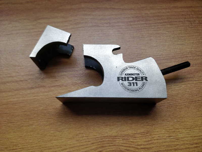
I then used the table saw to cut a rebate into the fixed jaws. I (deliberately) cut it a bit too shallow so that I could tweak it down to size with my shoulder plane. I then proceeded to drop my shoulder plane on the floor at the end of a stroke:

dropped_shoulder_plane_800.jpg


That made one or two rude words come out of my mouth...

Thankfully, I also have a Stanley #78, so I was able to use that to sort the rebate out while I wait for Axminster to tell me whether I can buy spare parts or if I'm in the market for a whole new plane. With hindsight, the #78 was the better tool for the job anyway, so I should have reached for that first!

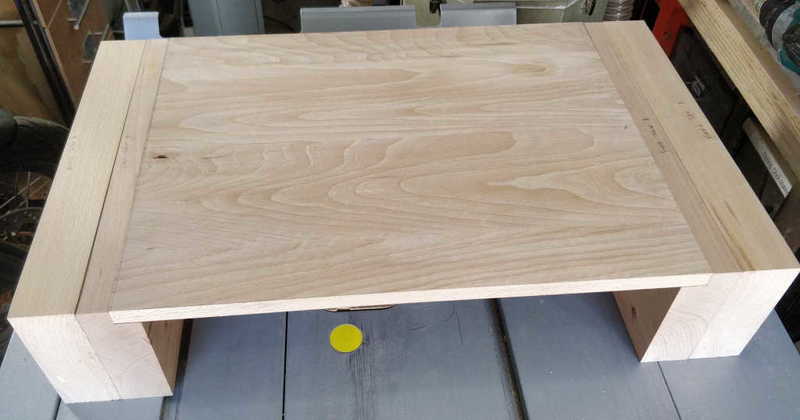
I then did a quick test fit of the jaws and table top:

portableworkbench_jaws_and_top_800.jpg


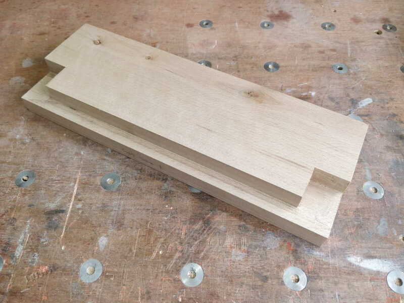
Next job was to cut the blind rebate (is that the right word?) for the rail to sit in. I did this by cutting diagonally with a dovetail saw and then sorting the rest out with a chisel:

portableworkbench_fixedjawpredrilling_800.jpg


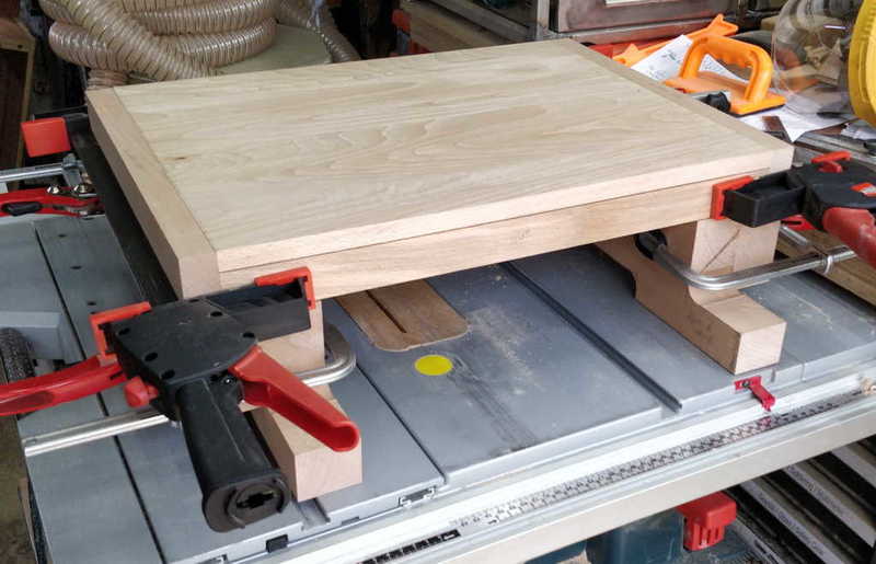
The legs were roughly shaped with a mixture of tools: 32 mm Forstner bit for the various radii, then hand saws, jigsaw & finally a saw rasp for a bit of finer shaping. I could then put it all sort-of-together to see how it would look (moving jaws removed for easier clamping in this photo):

portableworkbench_clamp_for_scale_800.jpg


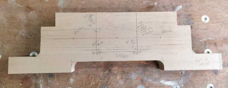
I knife-marked out the slots (in the feet) for the vice mechanisms in both feet and also marked all the hole locations in pencil. Here's the foot that sits at the end with the conventional vice (I didn't take a photo of the other foot in this state) with the central vice mechanism area marked out:

portableworkbench_stdfootpredrilling_800.jpg


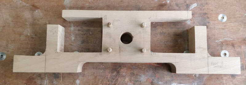
and here's what the other one looks like after drilling and then removing the wood in the area where the vice mechanisms will sit. Those slots were cut out with a hand saw for the accessible edges and a jigsaw for the inaccessible ones. I then used a chisel to tidy up the sawn edges.

portableworkbench_moxfootpostdrilling_800.jpg


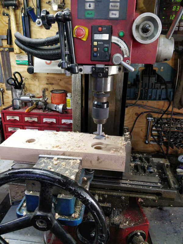
The way I've designed it, it's really important that the spacing of the three main holes is exactly the same on all four jaws (two fixed and two moving) and in some cases the feet as well. They also need to be perpendicular to the faces and a consistent distance from the top surface. The slide rails for the standard vice need to slide smoothly in the bushes (which will be mounted in holes in the fixed jaw and the foot at the standard vice end). They also need to slide over the threaded rod that forms part of the mechanism for the dual-screw vice. Any inaccuracies in the hole locations will mean the vice mechanism binds up.

Fortunately, I have a milling machine with a digital read out...

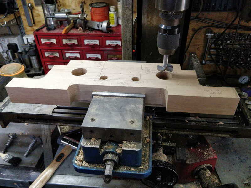
portableworkbench_setupfordrilling_800.jpg


The angle plate you can see on the right gives a consistent reference so that I don't have to re-zero the X-axis every time I place a new part in the vice. If there's a small offset in that axis it won't affect function: it'll just mean the edges don't quite match up. The jaws were all cut in the same setting, so there shouldn't even be an offset, but it's not the end of the world if there is: the important reference is the milling machine vice's fixed jaw, which references the top surface of each part.

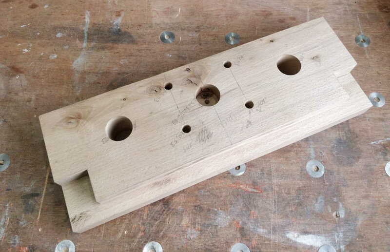
Everything looks like it's in the right place so far...

portableworkbench_moxfixedjawpostdrilling_800.jpg


That pretty much brings us up-to-date so far. More to follow.
 
Had a go at the following design as it struck me that he made it look very easy although I wasn't equipped quite right at the timed and the vice mechanism is a bit fiddly to nail on your first attempt but mine works, just not as well as I'd like it to.


lol...should have waited for you to post again as then I needn't have bothered. Elements of yours did look very similar.


Yes, I think that's the video that I watched that had the vice mechanism and is what I'm basing mine on. The prototype works well.
 
I made a little bit more progress tonight. I started by drilling out the holes in the foot and fixed jaw for the conventional vice end of the workbench. The fixed jaw was simple: all drilled from one side; three holes drilled through with two opened to a bigger diameter to depth 10 mm. The foot involved a couple of through holes and some other holes for jigsaw access:

portableworkbench_drilling_foot_800.jpg


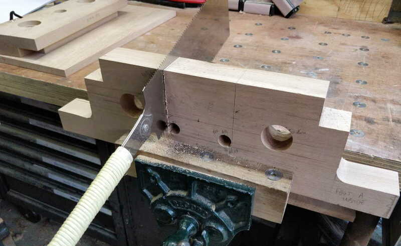
After that, I clamped the foot in the bench vice and sawed down to the holes:

portableworkbench_sawing_cutout_1_800.jpg


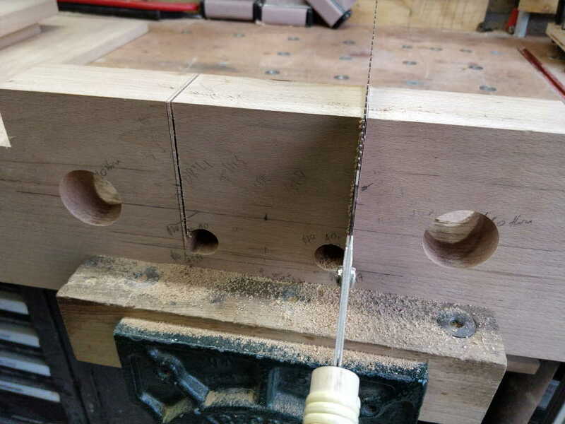
I was a bit more confident on the second cut and went closer to the knife line:

portableworkbench_sawing_cutout_2_800.jpg


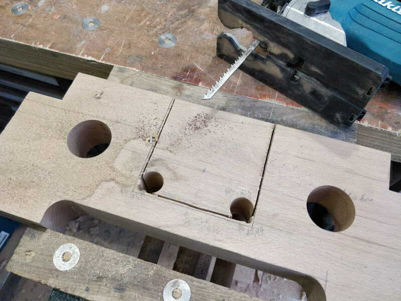
I then used the jigsaw to separate the two pieces:

portableworkbench_jigsawed_hole_800.jpg


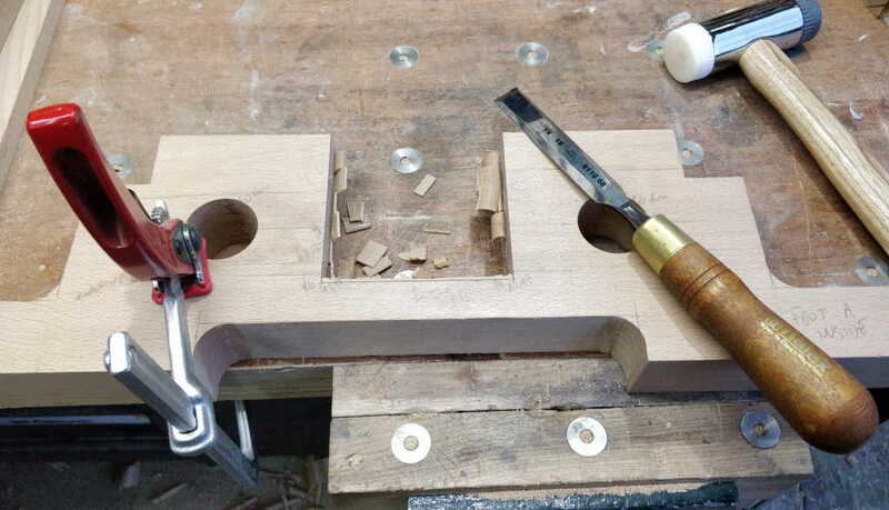
Then (after sharpening the chisels I used yesterday), I tidied it up:

portableworkbench_chisel_tidyup_800.jpg


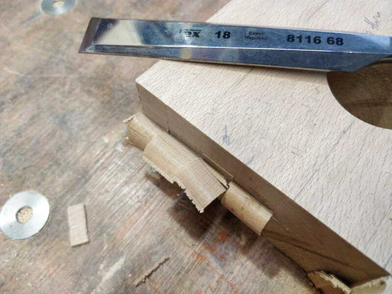
Am I the only one who finds end-grain chisel shavings like this extremely satisfying?

portableworkbench_chisel_satisfying_shavings_800.jpg


Then a bit of final tidying up of the slot with a saw rasp again (although no-one will ever see these faces) and I called it a day:

portableworkbench_std_fixedjaw_and_foot_800.jpg
 
Looks like a cool design. I made one pretty much off the pask makes video. Unfortunately I did only have hand tools for the build!

Mine only has the vise on the front and I'm glad as I use the extensions a lot given how small it is! I have however rigged up a janky moxon style vise on occasion on the side for dovetailing larger boards.
 

Attachments

  • 20210101_164157.jpg
    20210101_164157.jpg
    105.8 KB
  • 20210117_175159.jpg
    20210117_175159.jpg
    182.2 KB
Looks like a cool design. I made one pretty much off the pask makes video. Unfortunately I did only have hand tools for the build!

Mine only has the vise on the front and I'm glad as I use the extensions a lot given how small it is! I have however rigged up a janky moxon style vise on occasion on the side for dovetailing larger boards.

That looks fantastic. What finish did you apply?
 
I just went with an oil as I know it'll take a beating (doesn't looks quite so attractive months later!). I think it was Liberon finishing oil but not certain
 
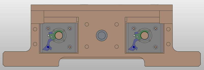
Last night I spent some time making a CAD model for the vice mechanism. I'm glad I did as I realised that I hadn't left enough space for the lock piece when it is disengaged. I'd obviously had a brain-dead moment when I was measuring the prototype and only measured it in the locked position. D'Oh!

Anyway, with a lot of playing around and tweaking dimensions, I've got it to the point where I think I can still fit it into the same overall envelope (100 × 80 × 60 mm). I'm going to make the frame out of 80 × 6 mm EN3B mild steel (as it's what I've got), so I didn't want it to be bigger than 80 mm deep. The dimensions of the various lock pieces are sufficiently different that I'm going to make another prototype of the lock piece rather than diving in and making three of them in one go. If it works I can use the new lock piece in one of the final mechanisms; if it doesn't work I won't have wasted as much steel!

The problem with the new design is that the shaft hole had to move up relative to the vice mechanism body, which means the vice mechanism body has to move down relative to the vice jaws. That's not in itself a problem, but it means that there's much less wood underneath the vice mechanism on the foot. At the standard vice end of the workbench, it doesn't matter as that bit of wood isn't doing very much, but at the dual-screw vice end, I was concerned that it might be a bit too thin for the feet to properly support the bench. In reality it might not be a problem as the foot will be glued to the fixed jaw, but to make it a bit stronger on the edges, I decided to add a couple of dowels on either side:

portableworkbench_model_moxon_foot_vice_mech_locked_800.jpg


The picture above shows the model of the vice mechanism in the position it will sit when the vice is locked (the view is shown from the outside, with the two jaws of the Moxon vice hidden, so the shaft would be turning clockwise to lock).

The picture below shows what it will look like fully unlocked:

portableworkbench_model_moxon_foot_vice_mech_unlocked_800.jpg


You can see that the overlap between the vice mechanism and the rail is much smaller than it was in the earlier models. I haven't decided yet whether I'm going to cut out a bit of the rail (as in the previous design) or cut out a bit of the vice mechanism.

I'm going to finish drilling all the various holes in the bits of beech before I get started on remaking the lock mechanism (so I don't have to change the milling machine set-up), but I won't enlarge the cut-outs for the mechanism until I've tested the new lock mechanism design. One benefit of the new lock design is that all of the parts of the mechanism (apart from the cut-in-half nut and the cut-in-half tube) can be made out of 10 × 16 mm steel bar; the previous version had three different sizes.

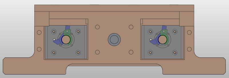
Here are a couple of views of the model of the whole workbench (minus the top) updated to include the vice mechanisms:

portableworkbench_model_vice_with_mechanism_1_800.jpg


portableworkbench_model_vice_with_mechanism_2_800.jpg
 
I think I've finished all the milling-machine drilling now (and I've given the milling machine a very thorough clean & oil!)

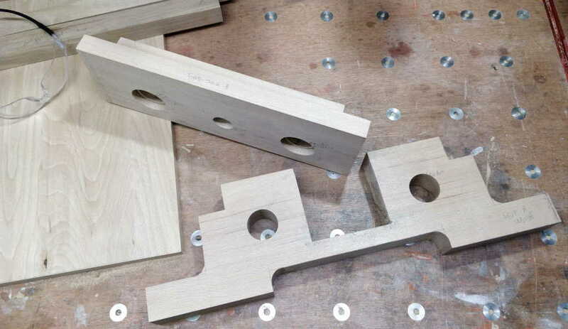
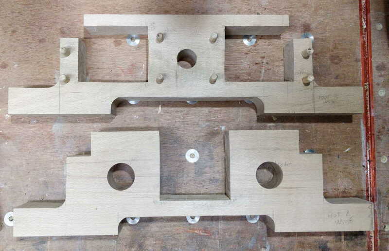
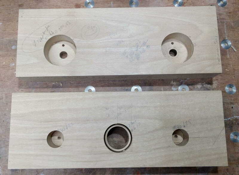
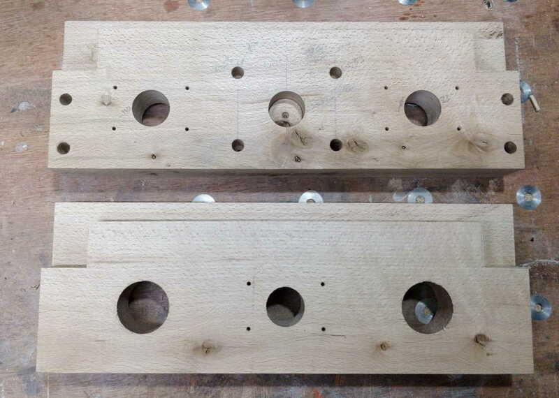
The feet now look like this (top one is the dual-screw end, bottom one is the conventional vice end - and likewise for all the other photos in this post):

portableworkbench_feet_800.jpg


I still need to enlarge the cut-outs for the vice mechanism but as mentioned in the previous post that can wait until later.

The inside face of the moving jaws:

portableworkbench_movingjaws_inside_800.jpg


The blind holes in the conventional vice jaw are for the slider rails. The small holes at the bottom of the pocket in the dual-screw vice jaw are for dowel pins. They'll make sure the slotted bushes go in with the slot aligned properly. The through holes are currently just 15 mm. Once the (brass) slotted bushes are in place, I'll use a bearing bit in my little router to make the beech hole match the slot in the brass. The bearing on my flush router bit will fit through that hole to get me started.

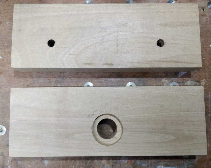
The outside face of the moving jaws:

portableworkbench_movingjaws_outside_800.jpg


The photo above makes the larger hole in the bottom jaw look really distorted, but that's just a photo artifact: it looks round and concentric to me.

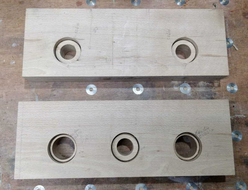
The outside face of the fixed jaws:

portableworkbench_fixedjaws_outside_800.jpg


For reasons I can't quite think of right now, I decided to make the screw bushes have a flange on them. It will probably look a bit better (and be easier to glue in place), but it would have been simpler to stick close to the model and just have tubes as I already have tube that would do the job perfectly! Ah well, a bit more turning is not necessarily a bad thing: it is my favourite type of metalwork after all!

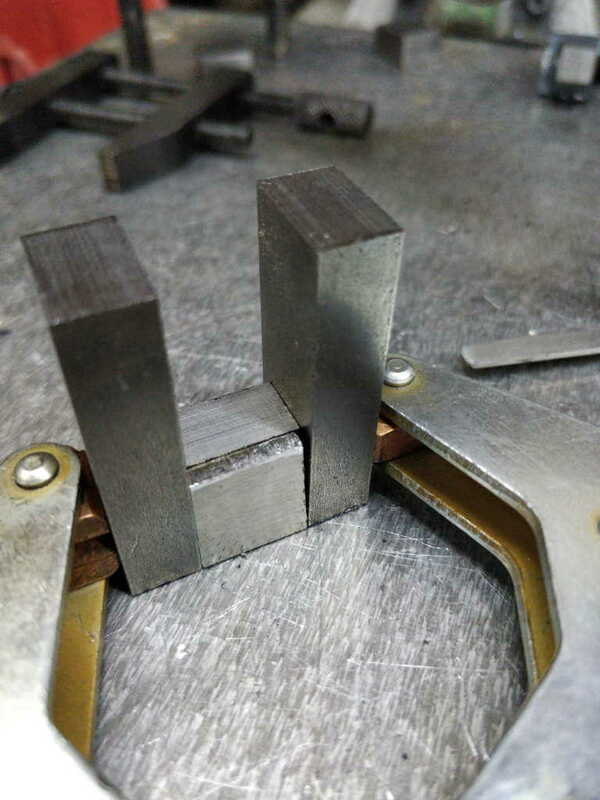
The inside jaws. These now have pilot holes for the vice mechanism to mount to. I'd originally intended these to be spaced out further, but with the way the milling machine was set up, there wasn't enough Y-axis travel to get to where the bottom holes were going to be, so I had to move them closer. When I make the vice mechanisms I could add more holes further out: I could then manually spot and pilot drill them. To be honest, I doubt it'll be necessary though so I probably won't bother.
portableworkbench_fixedjaws_inside_800.jpg


Next job is to make another prototype vice mechanism I think. Once that's done (and assuming it works) I can finish shaping the feet and get started making the myriad of bushes and suchlike
 
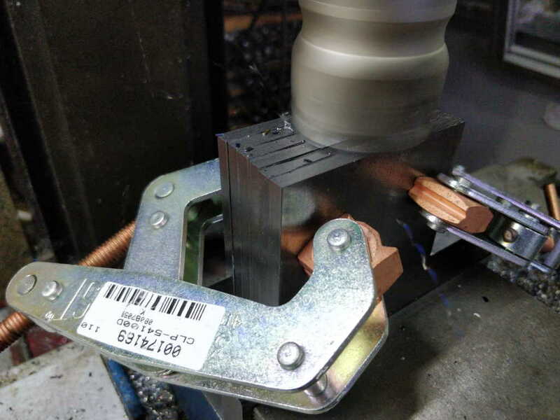
I work a 4½ day week so after doing a couple of chores I had most of the afternoon to make some more progress. Today was spent mostly on the milling machine. I've been working on the vice mechanisms. I decided to cut all the pieces to (slightly over) length on the bandsaw and then mill stuff to size. When I made the prototype, the only milling I did was the curved face on the bits that are welded to the outside of the half-tube. Everything else was cut with an angle grinder. I figured it would all fit a bit better (with less need for washers!) if I used the mill this time; given I've had to shrink it a bit as described in an earlier post, the tolerances are slightly more critical (although still not very tight at all), so the milling machine helps with that as well.

I'm generally working on the premise that I'll only make one vice mechanism for now (to check it'll work!), but some of the set-ups lend themselves to doing all the parts at the same time, so where that's the case I've done so.

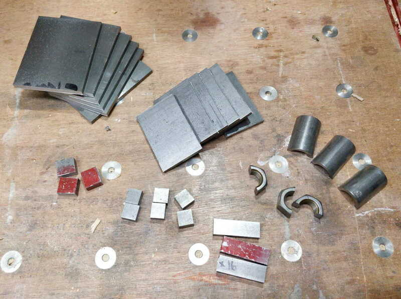
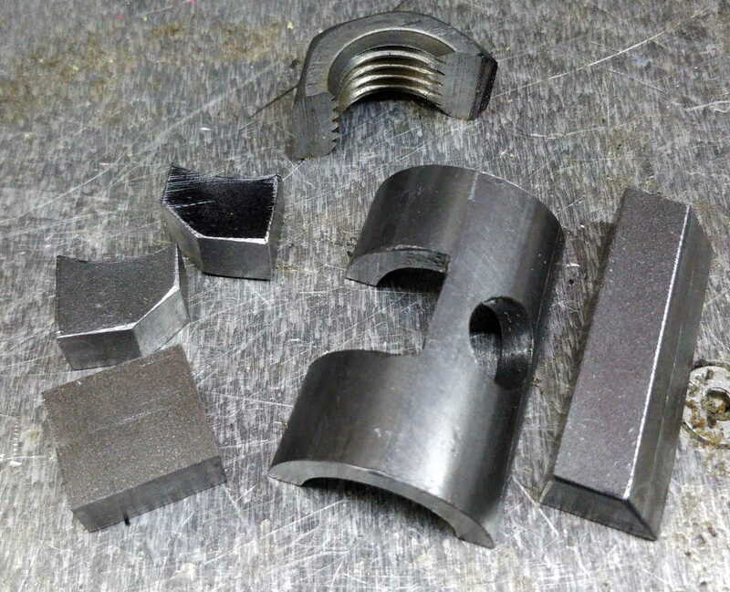
Here are all the parts fresh off the bandsaw: from left to right and top to bottom: the front & back plates of the box, the side plates of the box, the half-tubes on which the threaded rod slides, the half of the hinge that's welded to the nut, the half of the hinge that's welded to the tube, the jam bar that locks the mechanism and the half-nut.

vicemechanism_sawn_parts_800.jpg


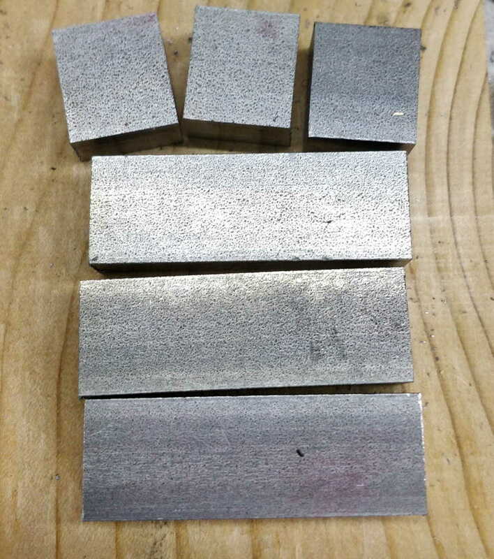
I started by facing the jam bar and nut hinge blocks to length. I didn't bother with the tube hinge blocks at this point as they are more complicated.

vicemechanism_facing_parts_800.jpg


vicemechanism_faced_parts_800.jpg


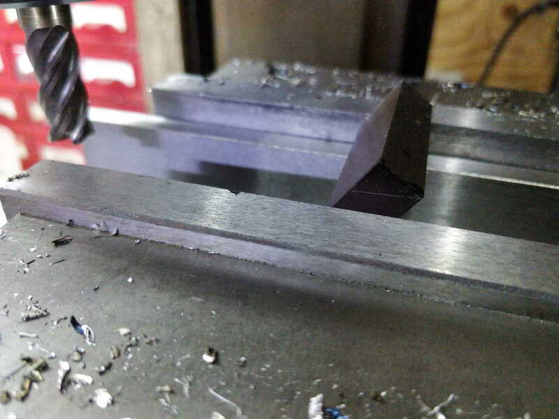
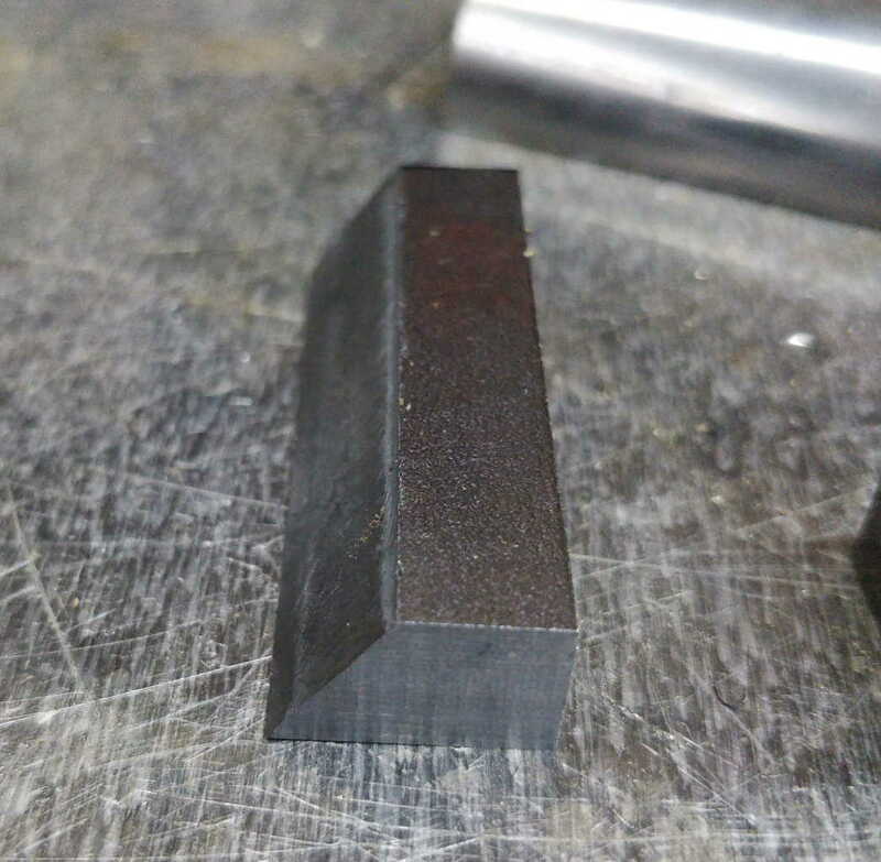
The nut hinge blocks (top) are basically finished now. After they've been welded to the nut, I'll drill the hole for the hinge bar, but I don't want to do that yet. The jam bars need a chamfer on the back edge. The chamfer isn't especially critical, so I just marked it up on the end and eyeballed it level in the vice.

vicemechanism_eyeballed_chamfer_800.jpg


et voila (I've only done one of these so far):

vicemechanism_finished_chamfer_800.jpg


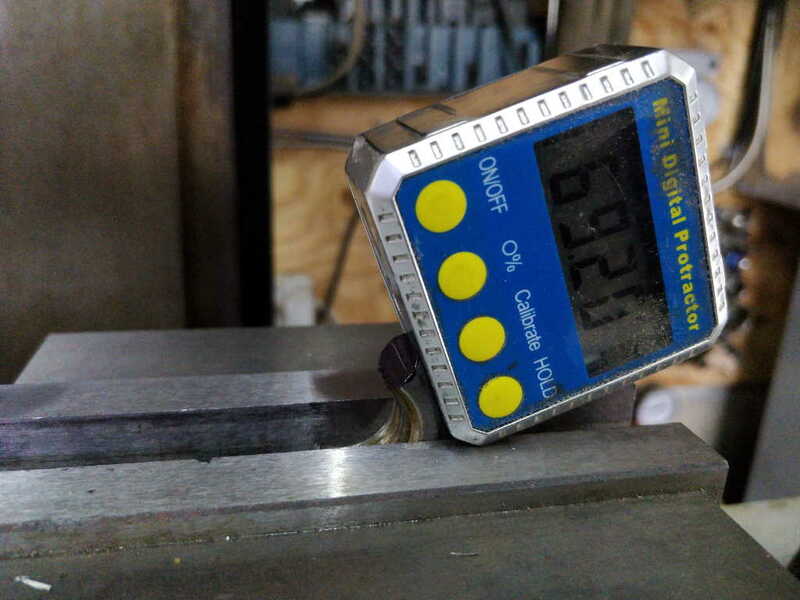
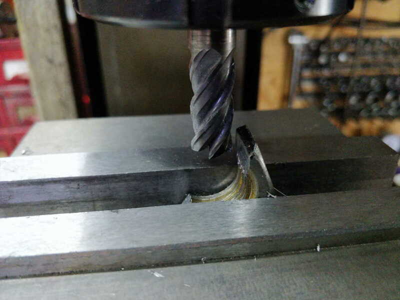
Next up was a bit of relief that's needed on the nut. Last time this was done after welding, using an angle grinder. This time I thought I'd just mill it off while the nut is free (again only one done so far). The set-up looked like this (the angle was fairly arbitrary, but the angle gauge will mean I can do the others at the same angle if it works):

vicemechanism_nut_relief_setup_800.jpg


... and the result looked like this

vicemechanism_nut_relief_finished_800.jpg
 
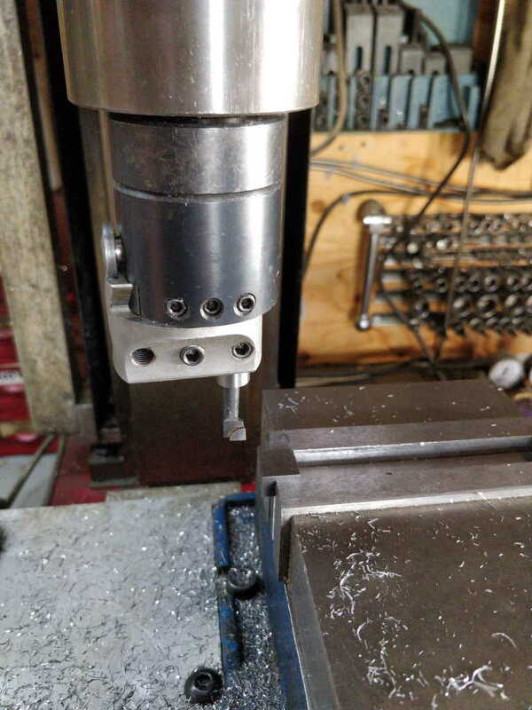
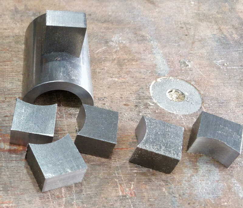
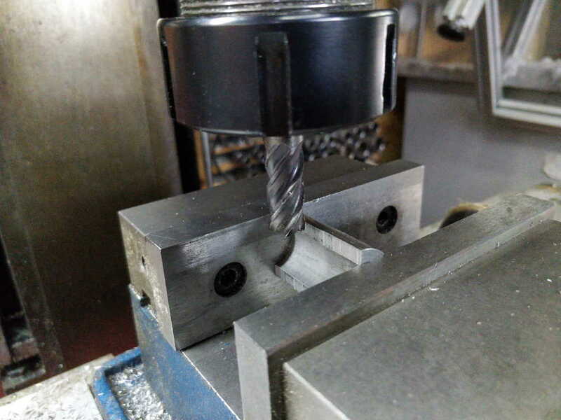
The tube hinge blocks take a bit more work than the other parts. First of all I cut the curved face. It made sense to do all six them at the same time. It didn't take me very long to do as a result of the fact that the last thing I'd used my boring head for was the prototype I made over the Christmas break. As a result the head was already set at exactly the right diameter, which made things very straightforward.

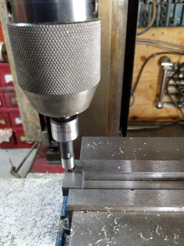
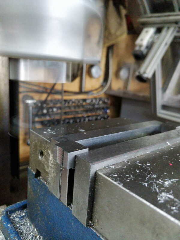
First I mounted a block on the end of the vice (with another block at the other end of the vice to stop the jaws from wandering) and used an edge finder to find the centre of the block (in Y). I moved the Y axis to the centre and locked it.

vicemechanism_curved_cutout_finding_centre_800.jpg


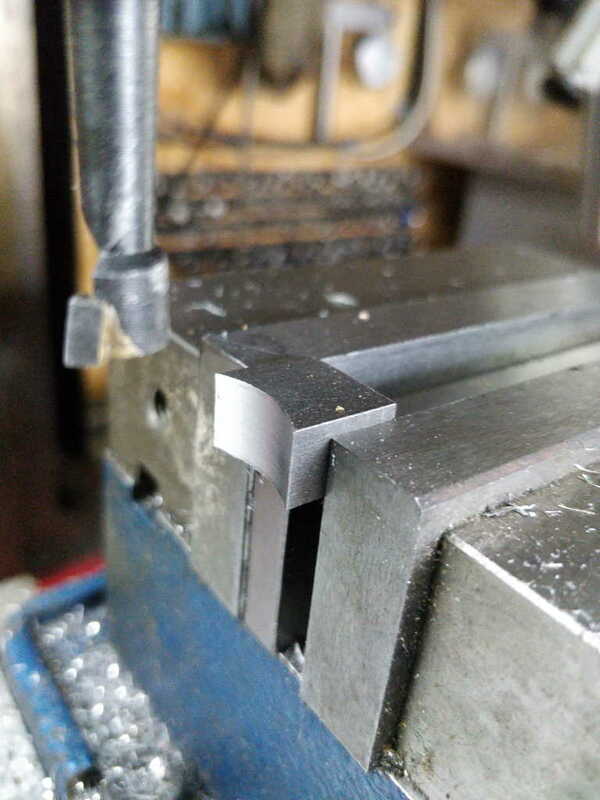
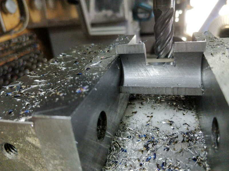
Then fitted the boring bar and made the cut-out in about 5 passes.

vicemechanism_curved_cutout_about_to_cut_800.jpg


vicemechanism_curved_cutout_part_way_there_800.jpg


vicemechanism_curved_cutout_done_800.jpg


vicemechanism_curved_cutout_all_done_800.jpg


I then machined two of these blocks to length and added a chamfer on one corner. I didn't take any photos of that, so you'll just have to imagine it!
 
Next up was the half-tube. I mounted this in the milling vice:

vicemechanism_halftube_in_vice_800.jpg


and milled a slot in the middle. That took a bit longer than cutting it with an angle grinder, but it's much neater!

vicemechanism_halftube_milled_slot_800.jpg


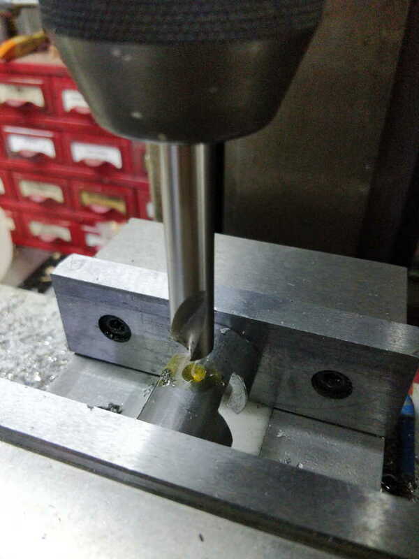
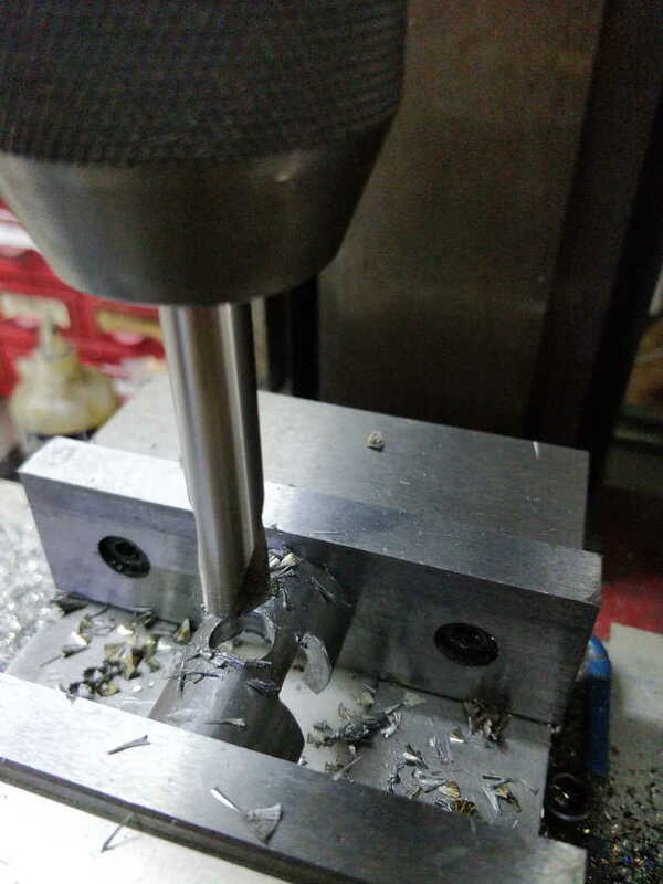
Next I mounted it on a single parallel with the parallel going through the new slot, slid the parallel back out and drilled a hole for the magnet:

vicemechanism_halftube_drilling_magnet_hole_800.jpg


vicemechanism_halftube_drilled_magnet_hole_800.jpg


Here are all the lock mechanism parts together:

vicemechanism_lock_parts_800.jpg
 
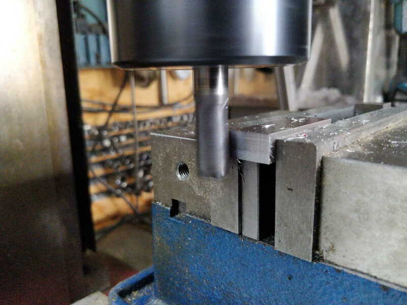
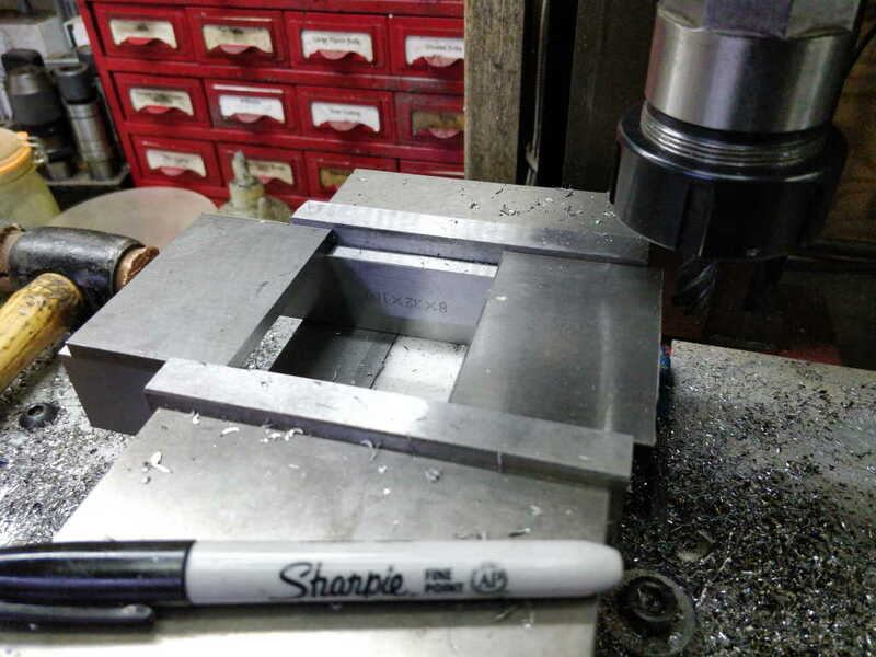
Last job for the day was sizing the bits that will make up the vice mechanism body. First of all I used the side of an end mill to square up one end of each part (none of these components need to be especially accurate and this is a quick and easy way to do it):

vicemechanism_body_squaring_one_end_800.jpg


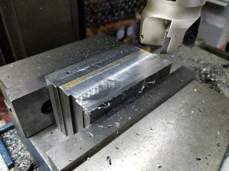
Then I got a carbide insert face mill (which is wide enough to cut all the bits in one go) and cut the opposite end to length - this ensures the two ends are parallel with one another and that's all that really matters here:

vicemechanism_body_starting_cutting_other_end_800.jpg


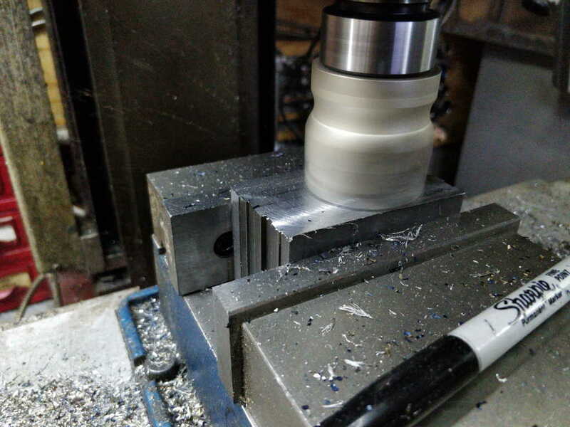
Action shot (one of the less significant advantages of my home-made X-axis power feed!):

vicemechanism_body_sides_action_shot_800.jpg


For the (longer) front and back pieces of the body, I added some extra clamps while face milling to make sure they didn't wobble around:

vicemechanism_body_front_action_shot_800.jpg


That's it for today. Tomorrow I'll drill the holes in the box front and back pieces for one vice mechanism (possibly using a bit of scrap instead of the real bits) and weld the lock mechanism together. If that works it's full steam ahead; if it doesn't work it's back to the drawing board!
 
I went out to the garage this morning with a plan of doing some welding, but realised the batteries were flat on my welding helmet. I need to pop out to a shop to buy some CR2032s, but in the meantime I thought I'd do some other bits and pieces.

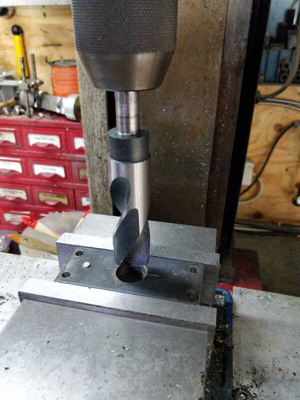
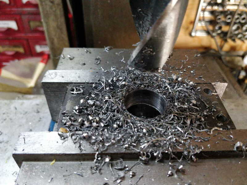
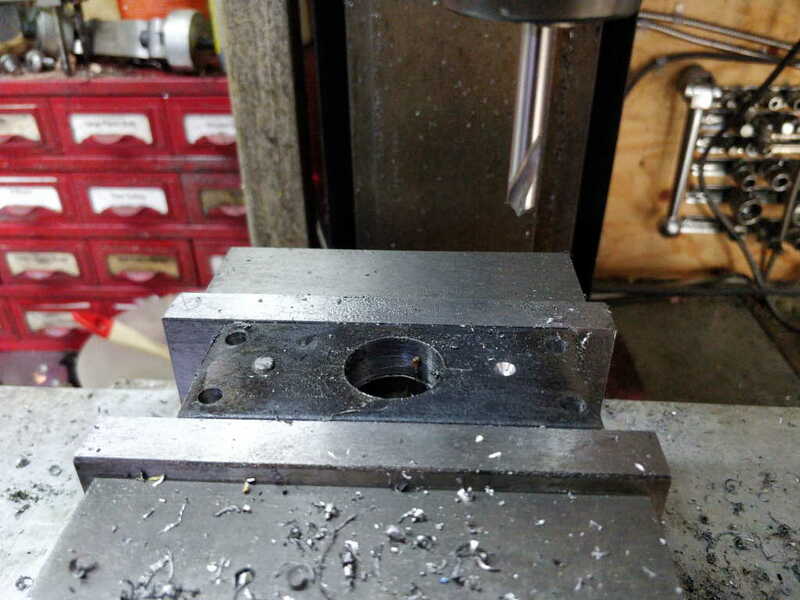
I started by taking the frame parts for the old prototype. I needed the jam bar in a different place, so I decided to drill both the threaded rod hole and the jam bar again (so I could ensure they were in the right place relative to one another). I also wanted to make the threaded rod hole be a tighter fit this time (it'll be a very loose fit in the final parts as the threaded rod will be held in alignment by some bushes in the wooden parts) so I could check everything works properly with the spacing set right.

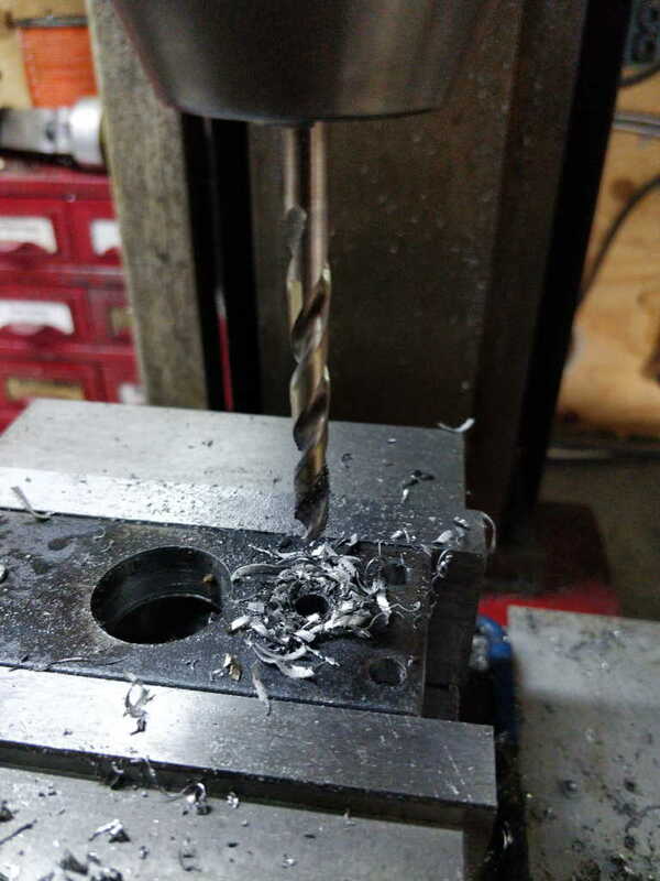
I started by drilling out the central hole to about 25 mm (I say "about" as these blacksmiths drill bits are anything but accurate!)

vicemechanism_prototype_drilling_out_frame_800.jpg

vicemechanism_prototype_drilling_out_frame_done_800.jpg


I then spot drilled and drilled out the hole for the new jam bar, on the other side to where the old hole was.

vicemechanism_prototype_frame_new_jam_hole_spotted_800.jpg

vicemechanism_prototype_frame_new_jam_hole_drilled_800.jpg


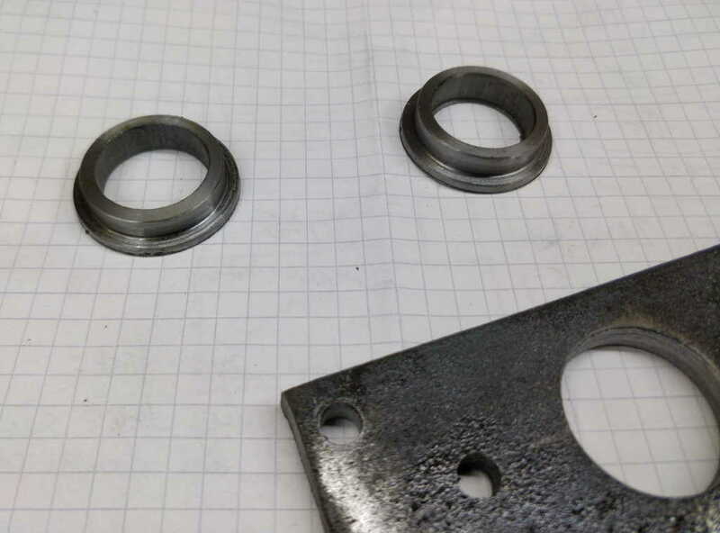
Finally, I used a bit of tube to make couple of simple bushes to bring the hole dimension down to 20 mm again (sized to be a tight fit in the hole I drilled earlier):

vicemechanism_prototype_bushes_800.jpg


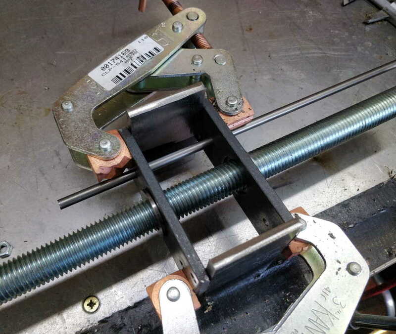
I could then assemble the frame ready for the mechanism when I get round to welding it.

vicemechanism_prototype_frame_800.jpg
 
There's going to be a lot of brass turning involved in this project. I imagine that if I were buying the brass, it would probably be more expensive than the rest of the project put together and I would have looked for an alternative material. However, I got a lot of brass out of a skip a few years ago and I've got enough in stock that this project will hardly dent my free brass collection!

Turning brass on the lathe tends to create clouds of swarf dust that fly all over the garage and cover every visible surface. As I've got a lot of brass turning to do, I decided it was time to grind a new tool (I've done this before on my mini-lathe, but never got round to grinding a larger tool for the larger lathe).

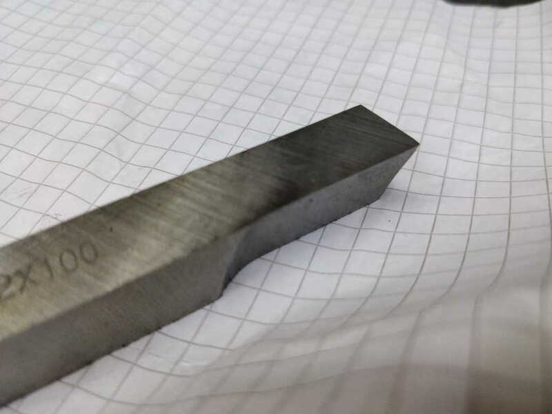
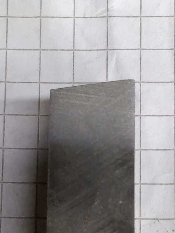
It's basically a left-hand turning tool with a flat top and some relief on the end and on the right-hand side, so quite easy to grind.

left_hand_brass_tool_800.jpg


After grinding to shape, I honed it on a fine India stone and added a very small flat on the end to give a smoother finish:

left_hand_brass_tool_flat_end_800.jpg


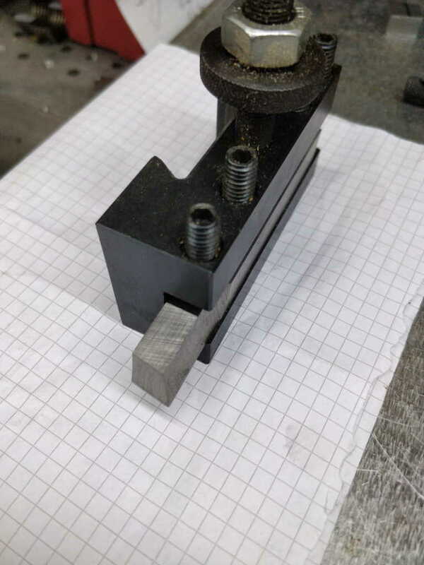
I then mounted it upside down in a tool holder, so the cutting tip is on the left like you'd get with a right-hand tool, but at the bottom of the tool:

left_hand_brass_tool_in_holder_800.jpg


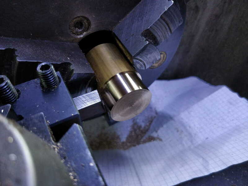
In use, the lathe runs backwards and the brass swarf that would normally be propelled straight up and all over everything gets fired straight down into the bed of the lathe. Some bits do still go all over the place, but the majority is relatively constrained. I did a quick test cut on some scrap with a bit of paper underneath to catch some of the swarf (I will probably save most of the swarf in case it comes in handy for various things, for example as a bed for heating stuff evenly).

left_hand_brass_tool_test_800.jpg


I guess I need to go and brave a shop on Saturday now so I can get some batteries and then see whether I can still weld after a very long hiatus!
 
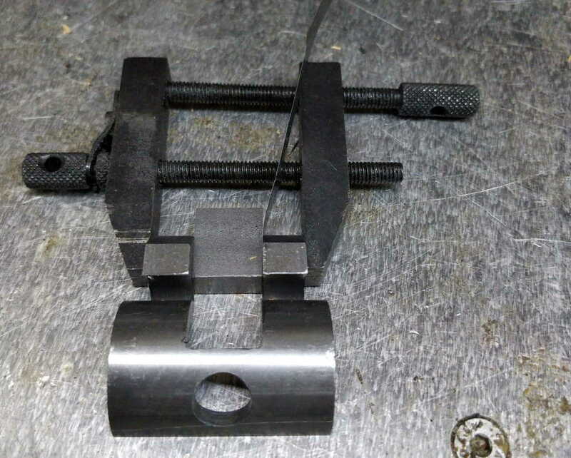
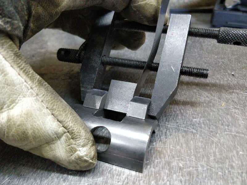
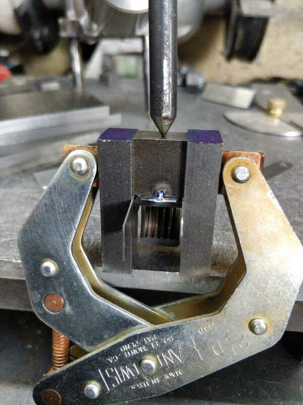
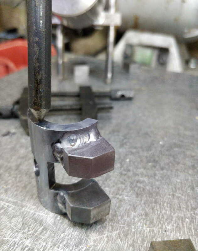
I started the welding with the half-tube. I used the hinge block from the nut as a spacer for the two hinge blocks for the tube. I added an old (and rather battered) feeler gauge in the middle as a spacer to be sure that it would all move after welding. I've got loads of bits of feeler gauge as I bought 3 cheap sets (to supplement an existing good one) and cut them up when I had a mini-lathe and no quick-change tool post: they made it slightly easier to set the height of the tool in the tool post. I don't use them for that any more, but they come in handy now and again as a spacer.

vicemechanism_setup_for_tube_welding_800.jpg


I then held the two pieces together in my hand while I tacked the two hinge blocks onto the tube. No filler rod for these tacks as I don't have three hands, but it's only got to hold for long enough that I can put some proper welds on.

vicemechanism_setup_for_tube_welding_held_in_place_800.jpg


Tacked in place...

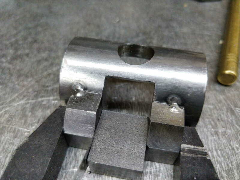
vicemechanism_tube_tack_welds_1_800.jpg


... and welded - note that I didn't weld on the inside of the hinge blocks to be sure that the weld beads wouldn't get in the way of the hinge operation. Spot the mistake...

vicemechanism_tube_welded_800.jpg
 
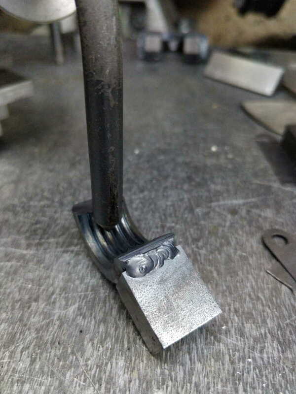
Next up was the hinge block on the nut. I wanted this to sit in the right place, so I used a few bits of metal I had lying around to help clamp everything up. I started by sandwiching the hinge block between two longer blocks, with a small piece of 3 mm aluminium to make sure the face of the hinge block is 3 mm back from the front of the clamping blocks:

vicemechanism_nut_hinge_bar_spacers_800.jpg


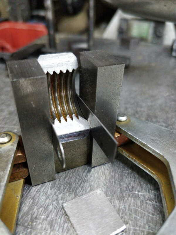
I then added the nut, flush with the front of the clamping blocks (and hence 3 mm from the face of the hinge block). The nut is slightly narrower than the hinge block, so I used a couple of feeler gauge bits to make sure it was centralised and held in place.

vicemechanism_nut_hinge_bar_ready_to_weld_800.jpg


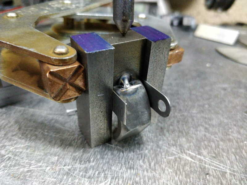
Then I could tack weld the first side:

vicemechanism_nut_hinge_bar_tacked_800.jpg


and the second:

vicemechanism_nut_hinge_bar_tacked_2_800.jpg


I then removed it from the jig and welded two sides (again leaving the sides that could interfere with the hinge motion):

vicemechanism_nut_hinge_bar_welded_800.jpg
 

Latest posts

Back
Top