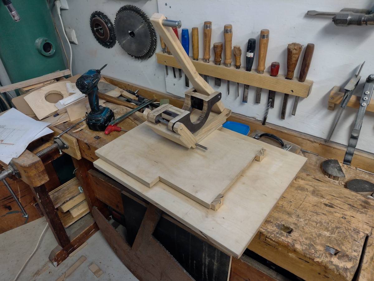
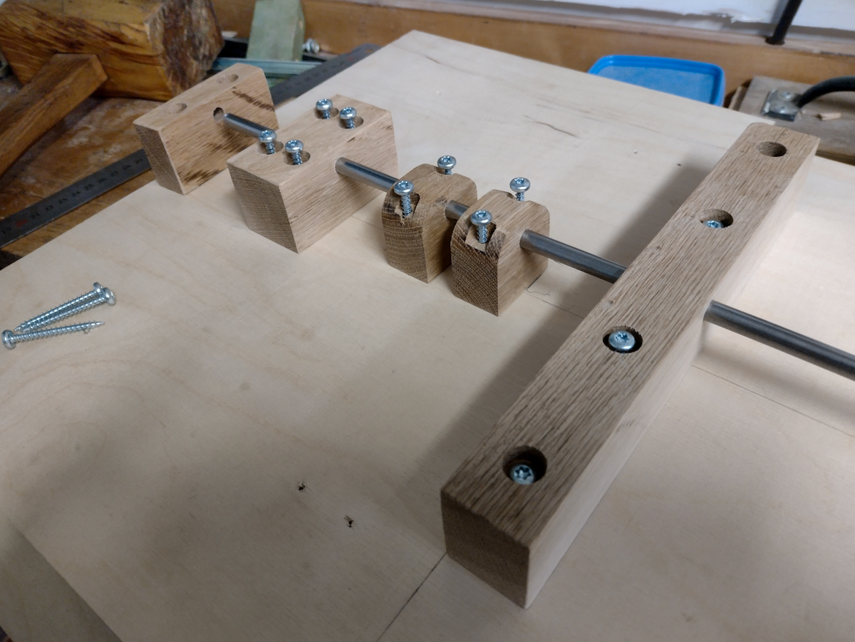
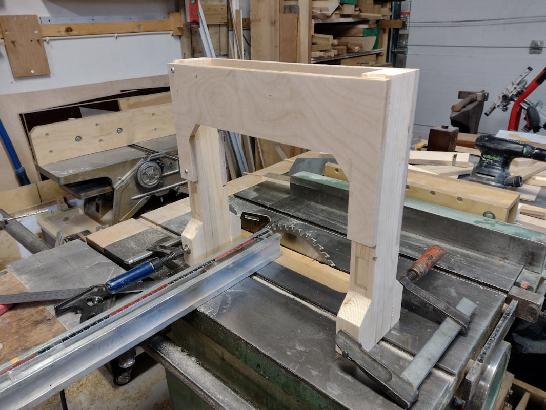
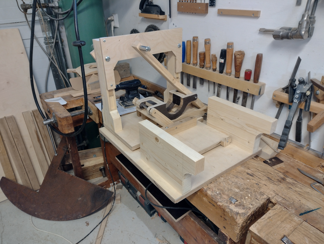
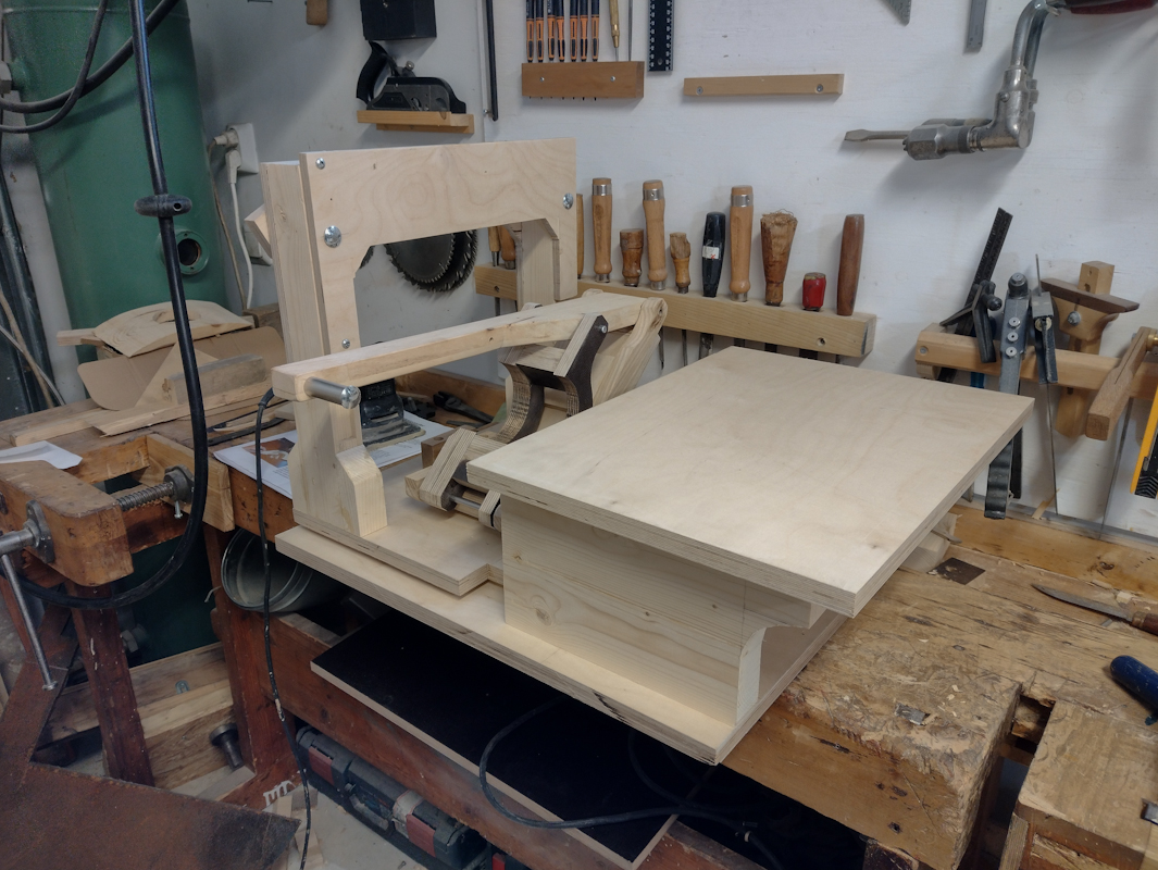
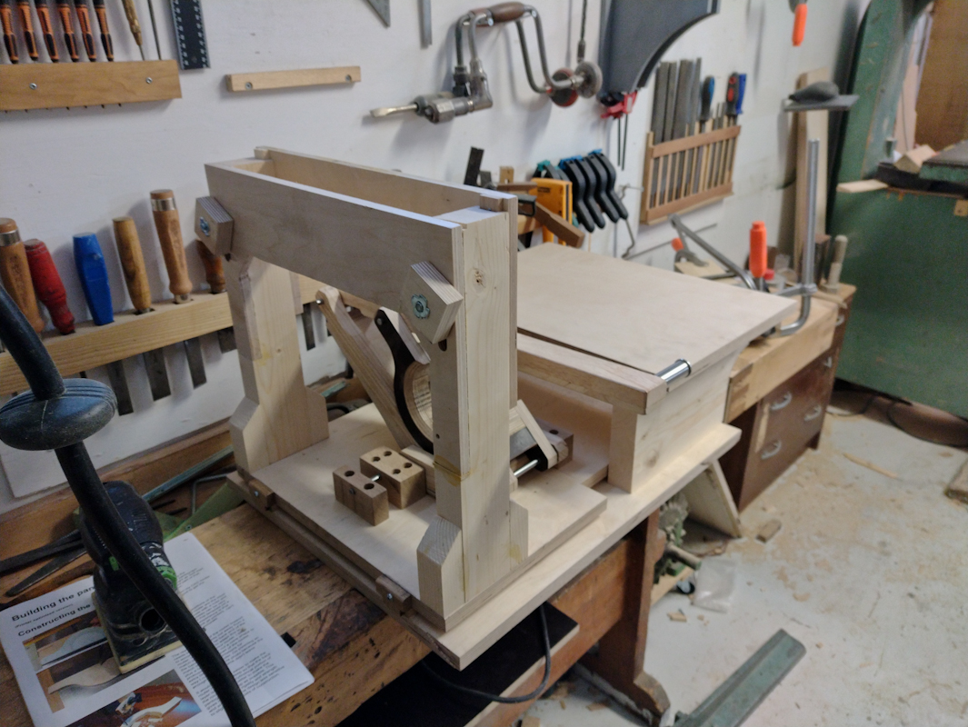
I bought these plans in 2017, I printed a lot of it out in color in folded and stapled book form because I have access to a very good printer at work. I started on it in 2018 and I got the linear glides mostly done as well as the holders for the router body. Around that time I took on a project that wasn't completed until 2020, the renovation of my milling machine so it got put on hold.
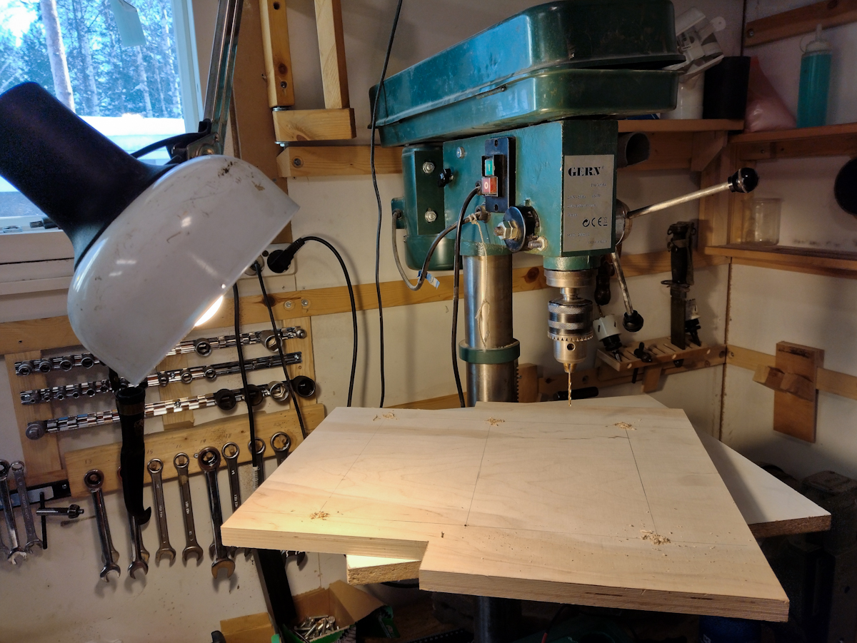
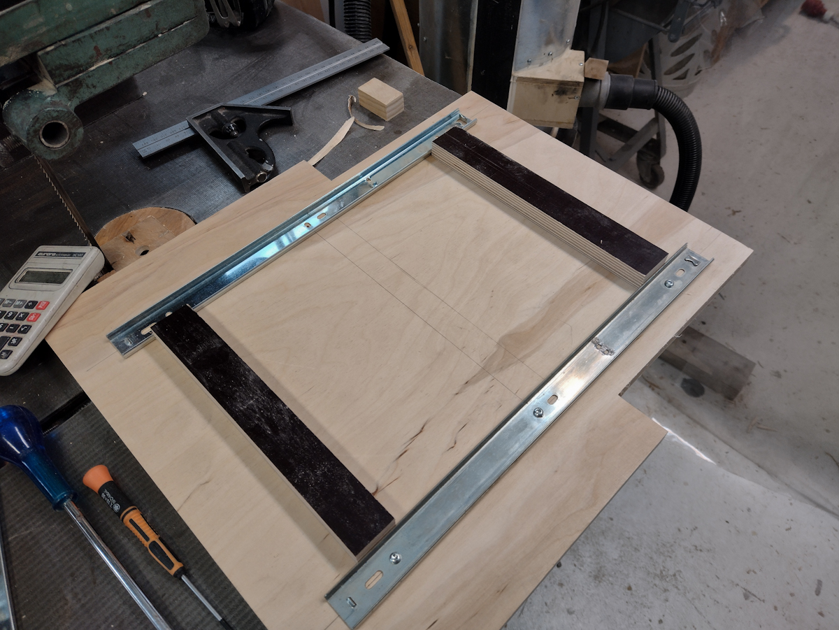
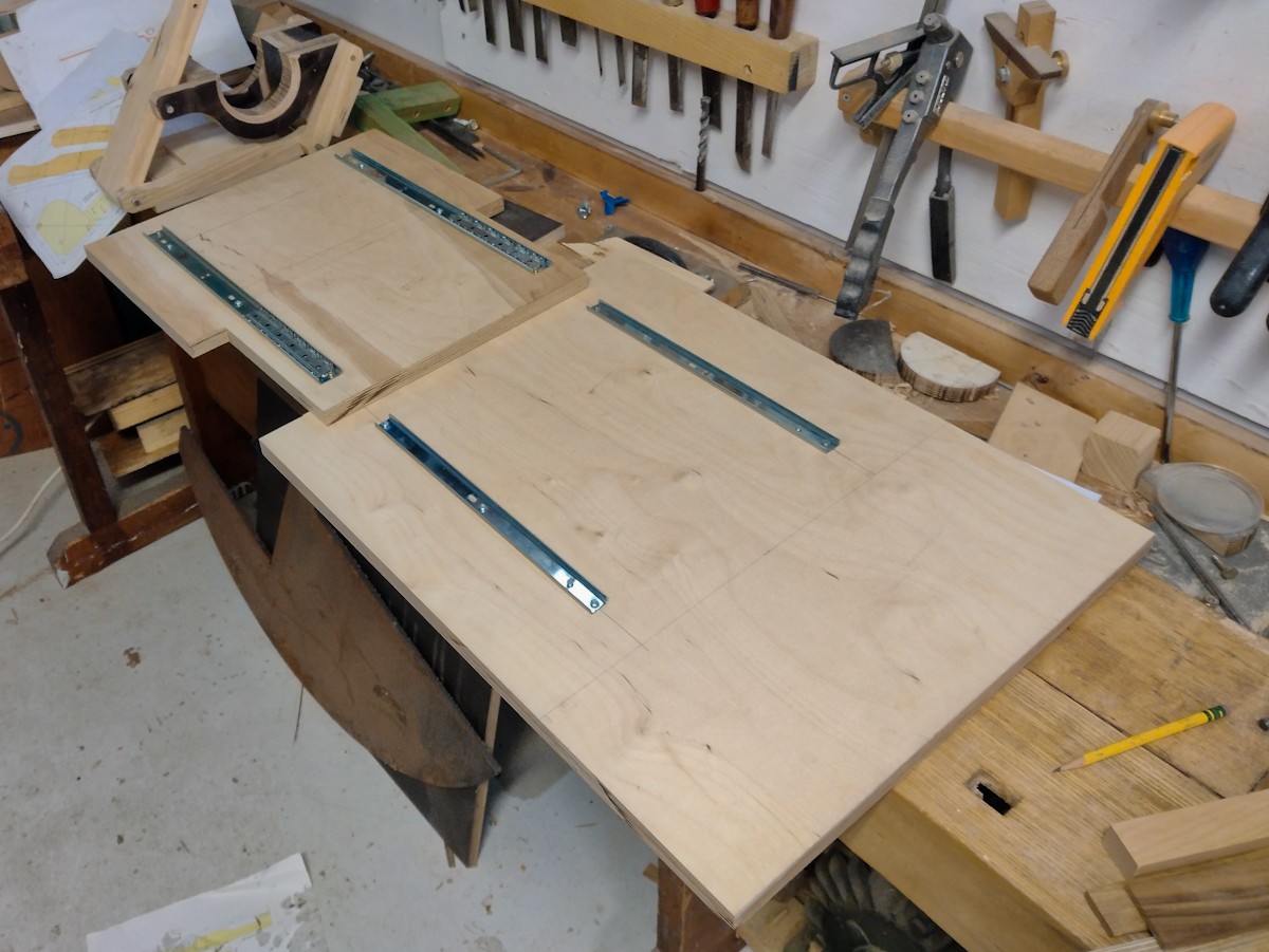
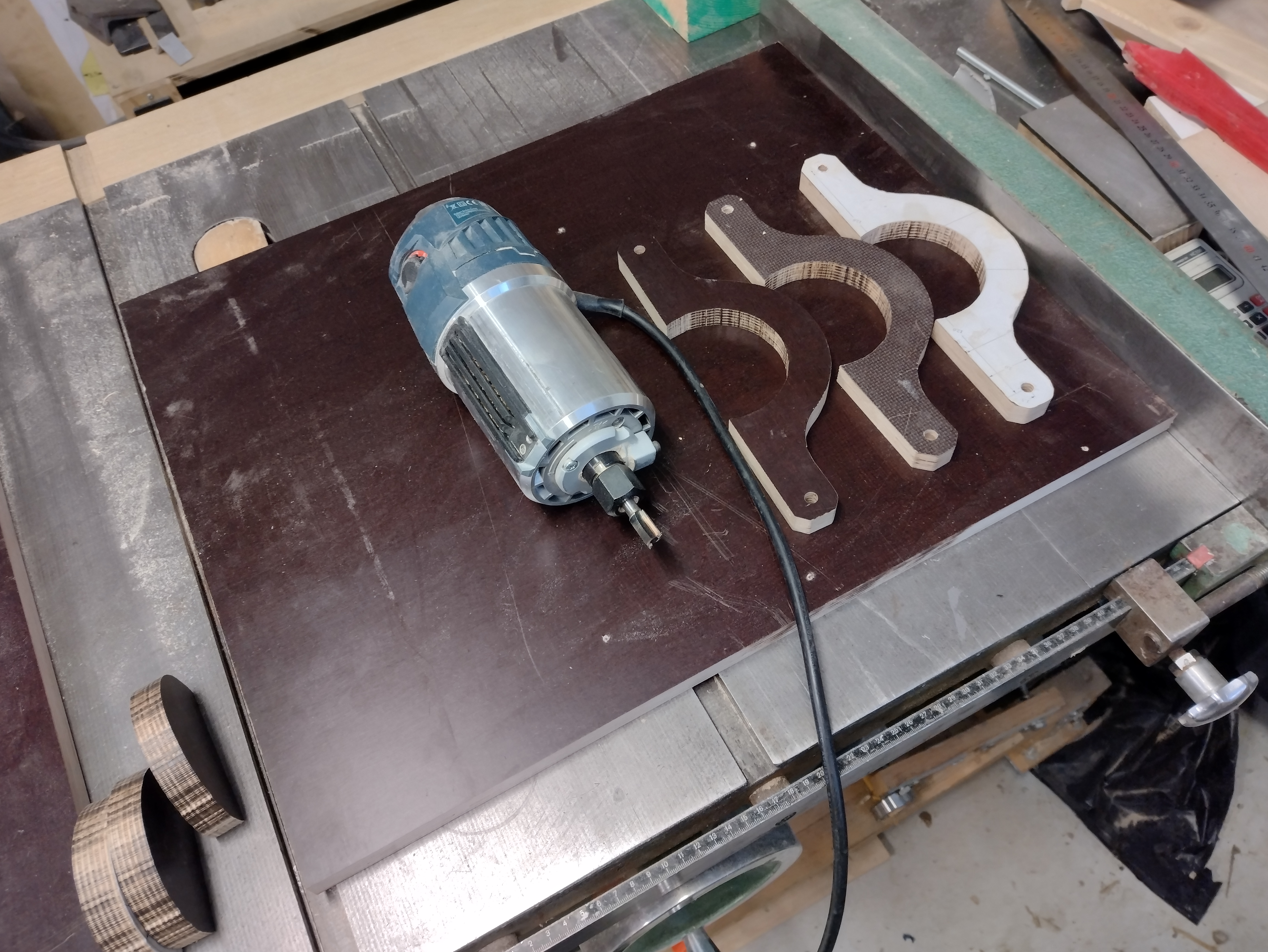
Well I'm starting it back up now. Last time I cut the outside of the three templates and drilled the holes. I used double sided tape to tape them all together so I could drill and cut them all as one part, in order to make it easier to keep the parts accurate.
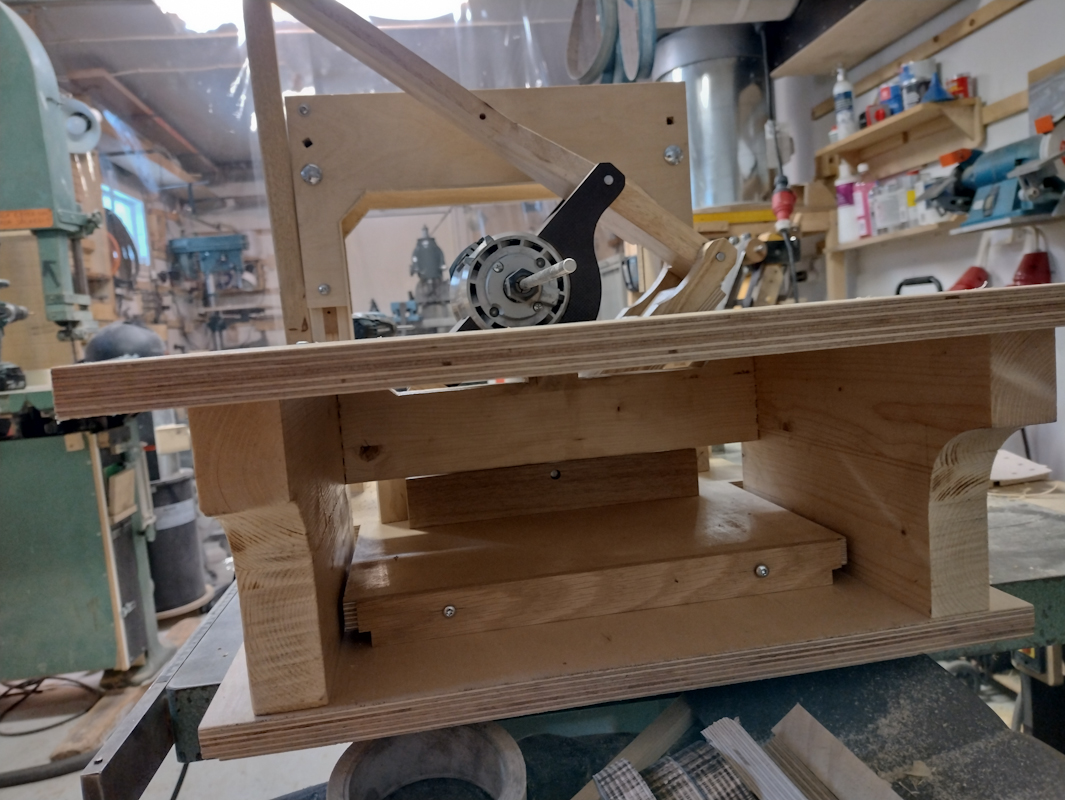
The big piece of plywood is the base. Not sure about using this film plywood but it's all I got. Still gonna have to buy more.
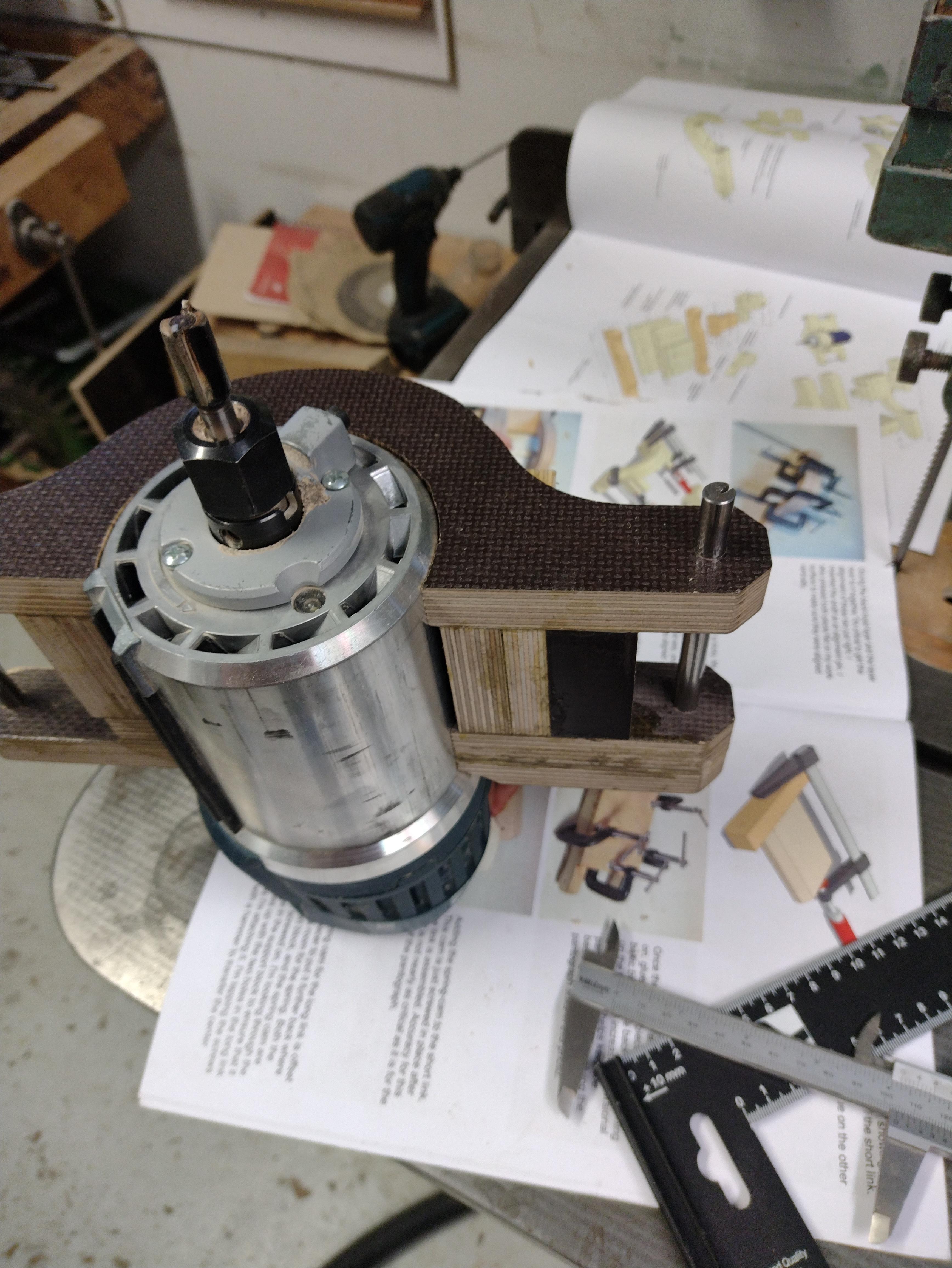
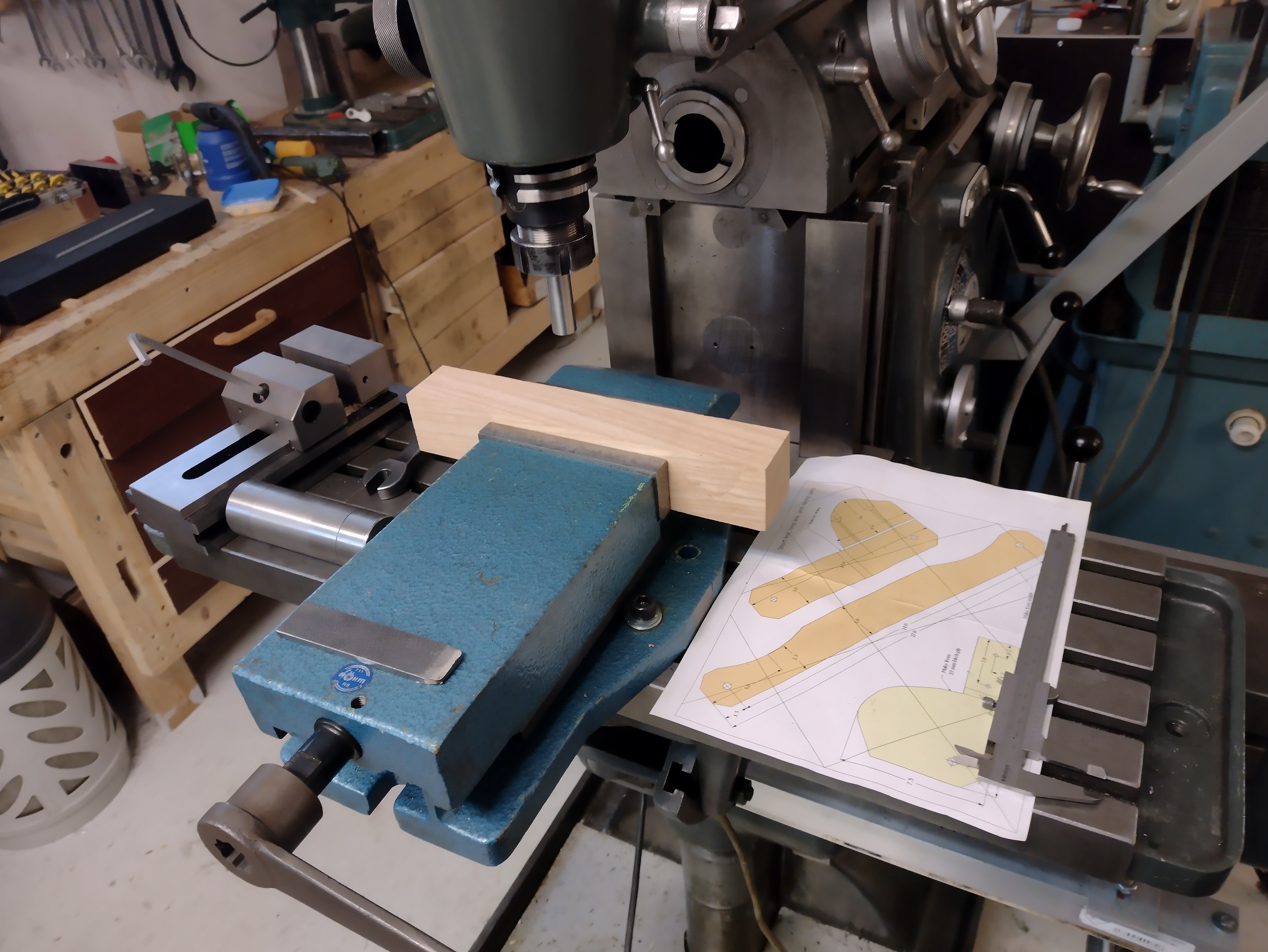
Moving on the long links, I am going to use my most accurate tool to lay out and dril the holes. My milling machine and DRO. I am going to make two links but I will do all the work on a single overly thick piece, then I'll rip the part on the table saw into two thinner pieces. That way I should get two identical parts. The accuracy of the links in the pantograph is the most critical part. I have an endmill that makes a little too tight of a fit for the 8mm shafting I am using, but this is good, that means I can ream to size using a reamer made from the shafting I will be using.
Long link assembled without glue:
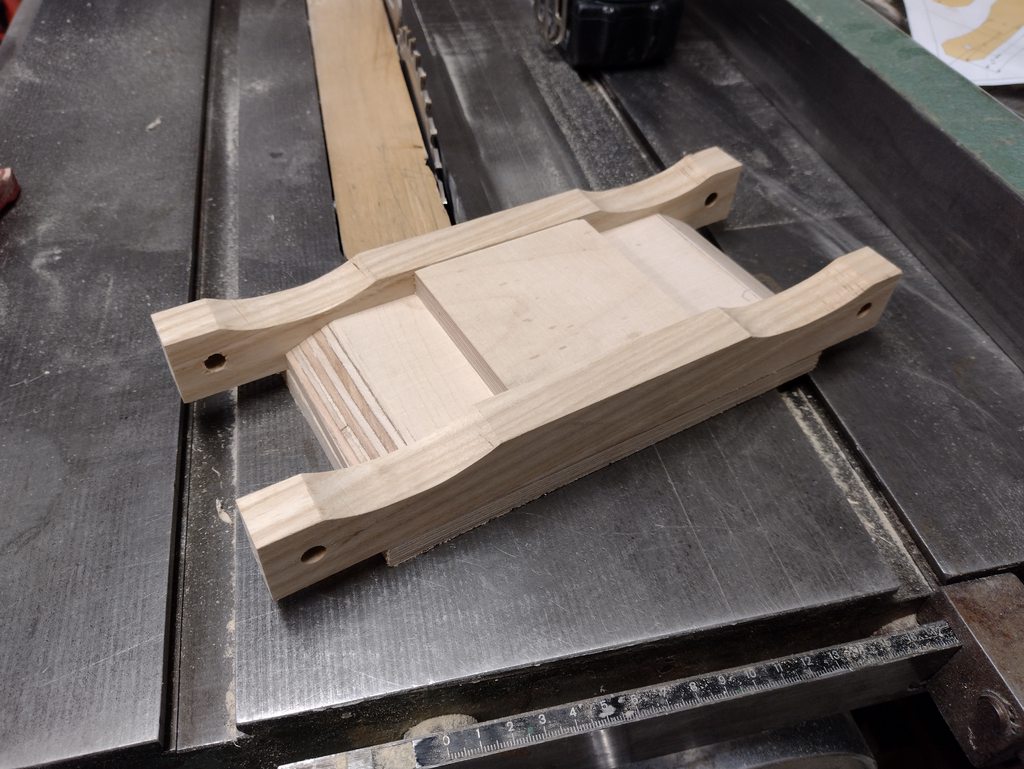
Matthias updated his plans in 2018 and made refinements to the machine. I am working from the original plans, but I will include the updates he made since they are gneuine improvements, I also have ideas of my own modifications. This part above has been simplied in design in the newer machine but functionally it's the same, I made it according to the old design.
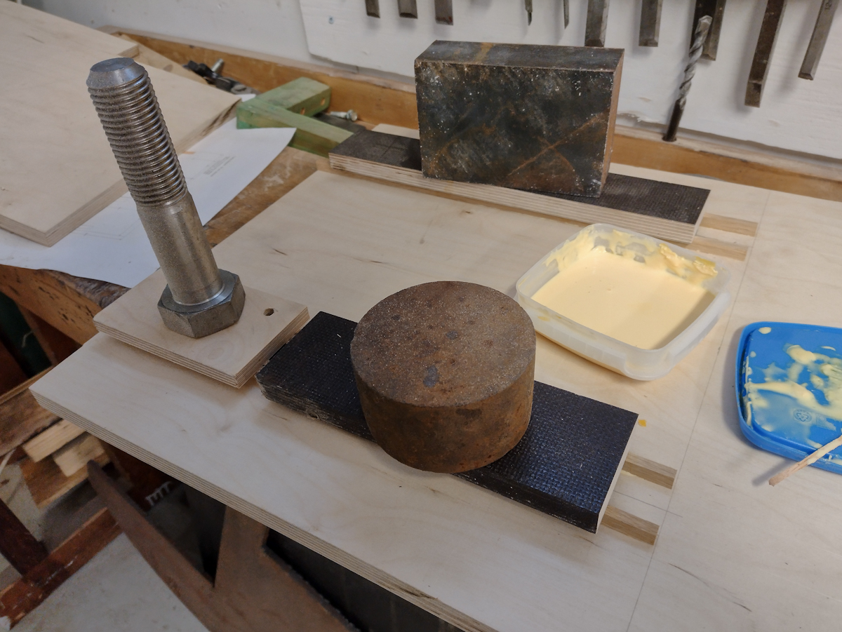
Gluing up parts, doing it in stages or the parts will move and it will be impossible to get straight.
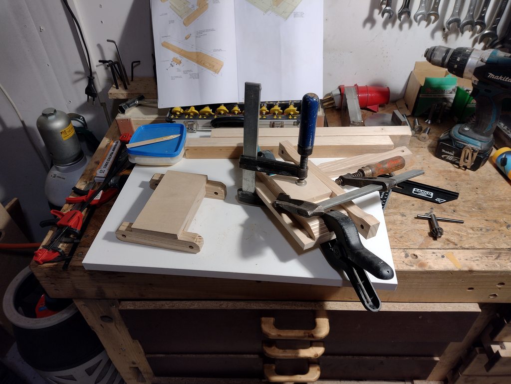
When I glue up the last component of the links and router holder I put the shafting in to properly orient everything. I then rested the links on two pieces of wood that is the same height before clamping up. That way all the links would be planar to each other and I avoid twist. Unfortunately this part must have moved anyway and it had a lot of twist (0.2mm). I mounted it in the mill and corrected the hole, but now it is oval:
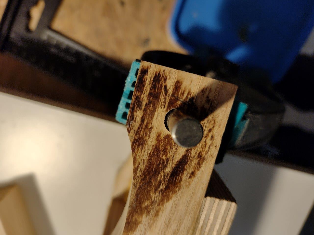
After that the twist was only a few hundreths which is good enough
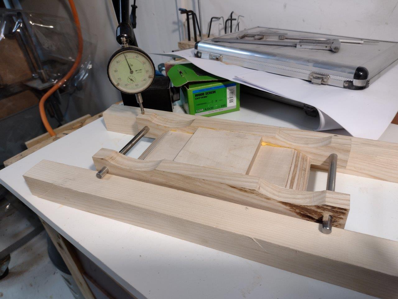
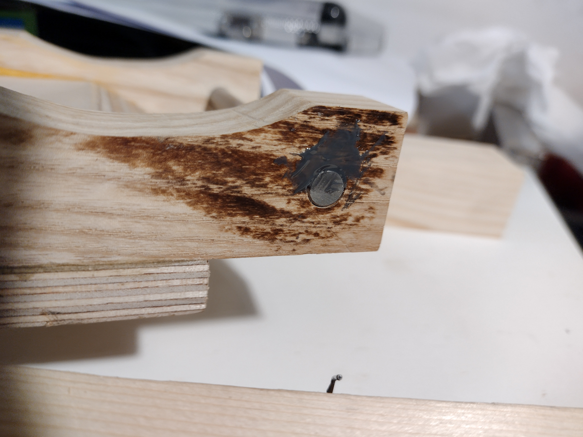
But the hole cannot be left oval so I fill the gap with epoxy and let it dry in place. I waxed the shafts so the epoxy doesn't stick to them.
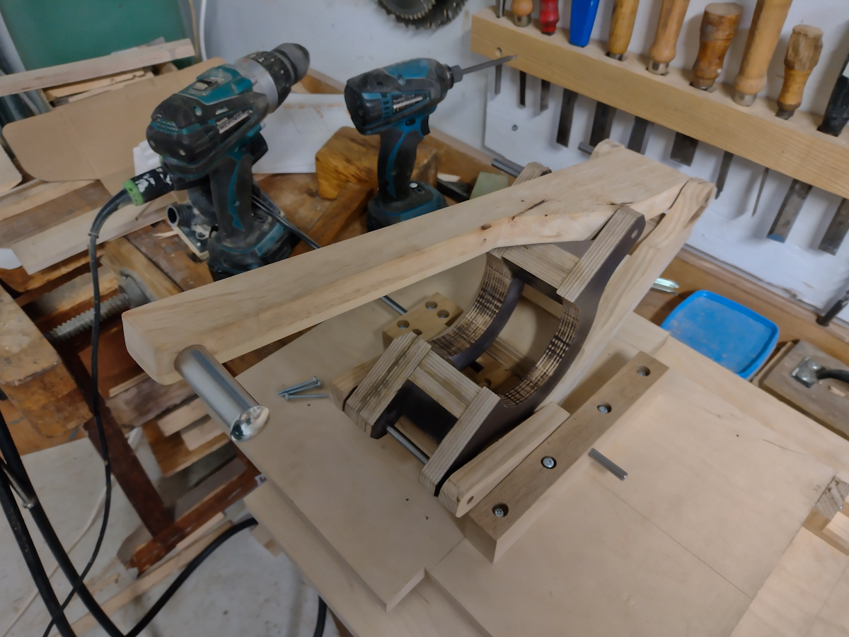
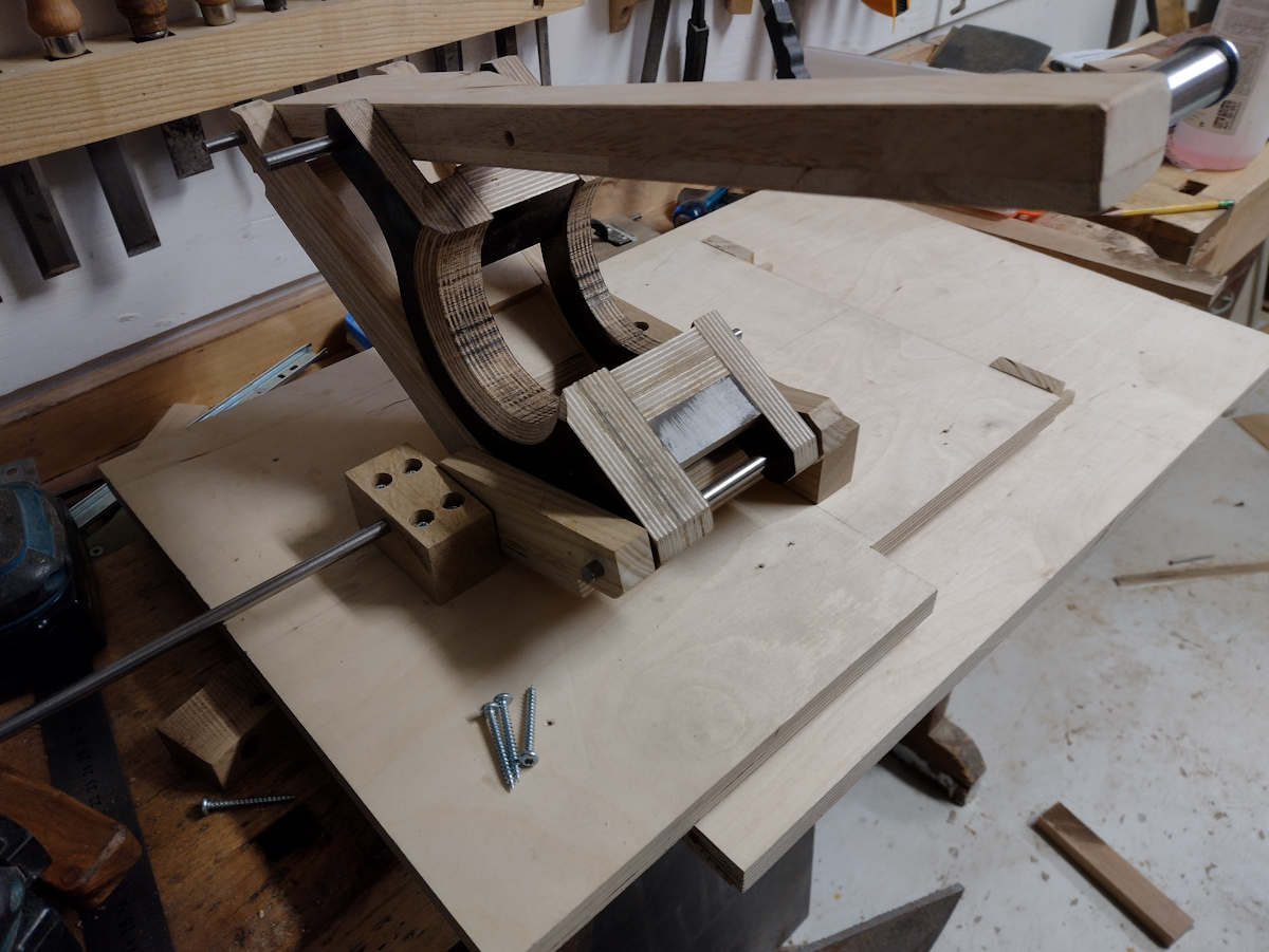
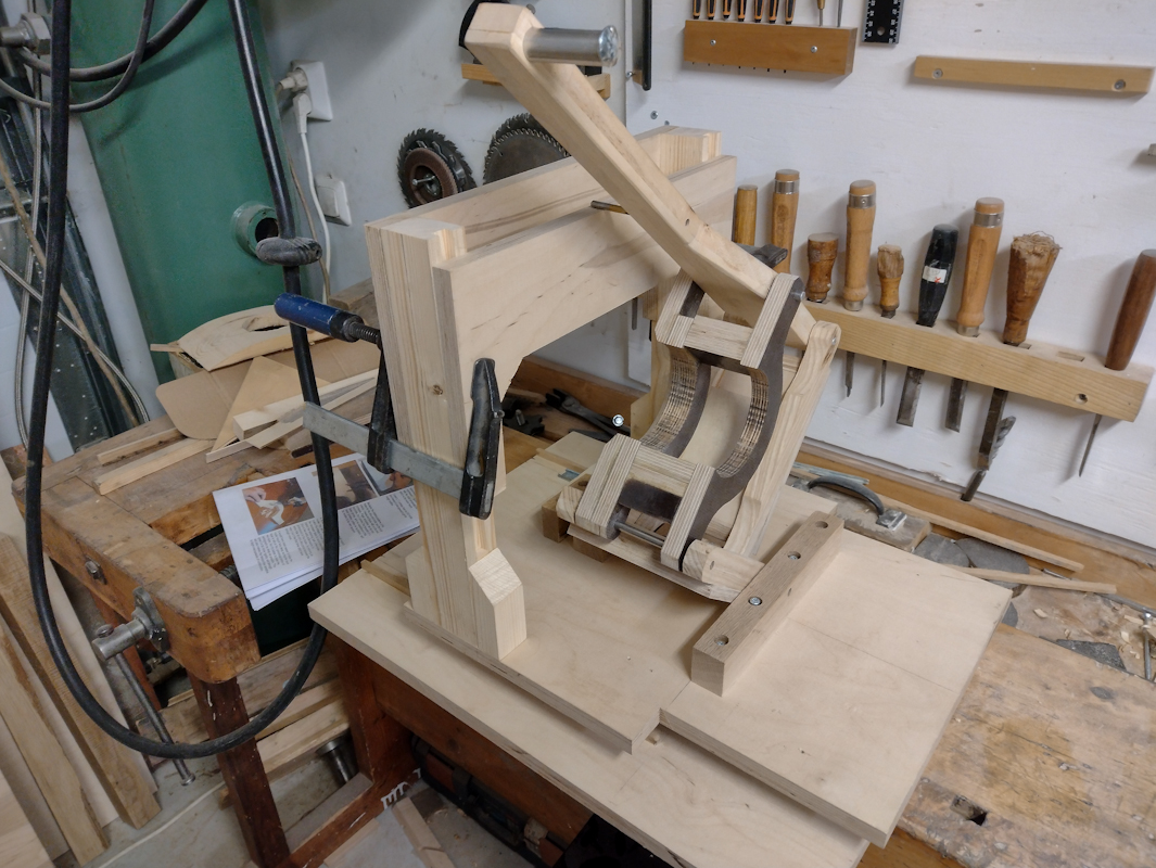
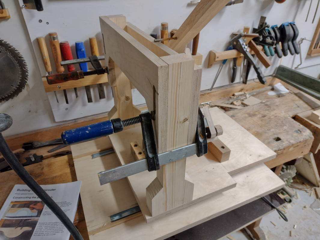
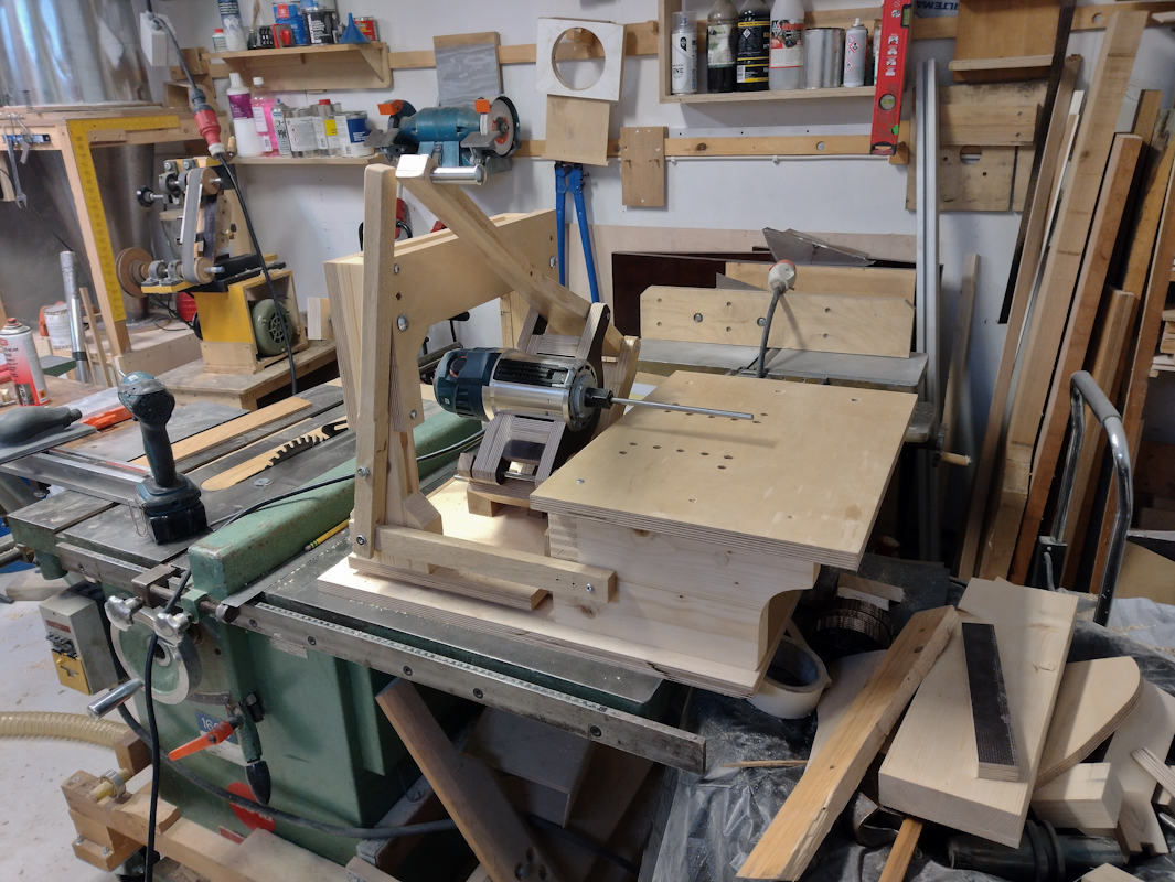
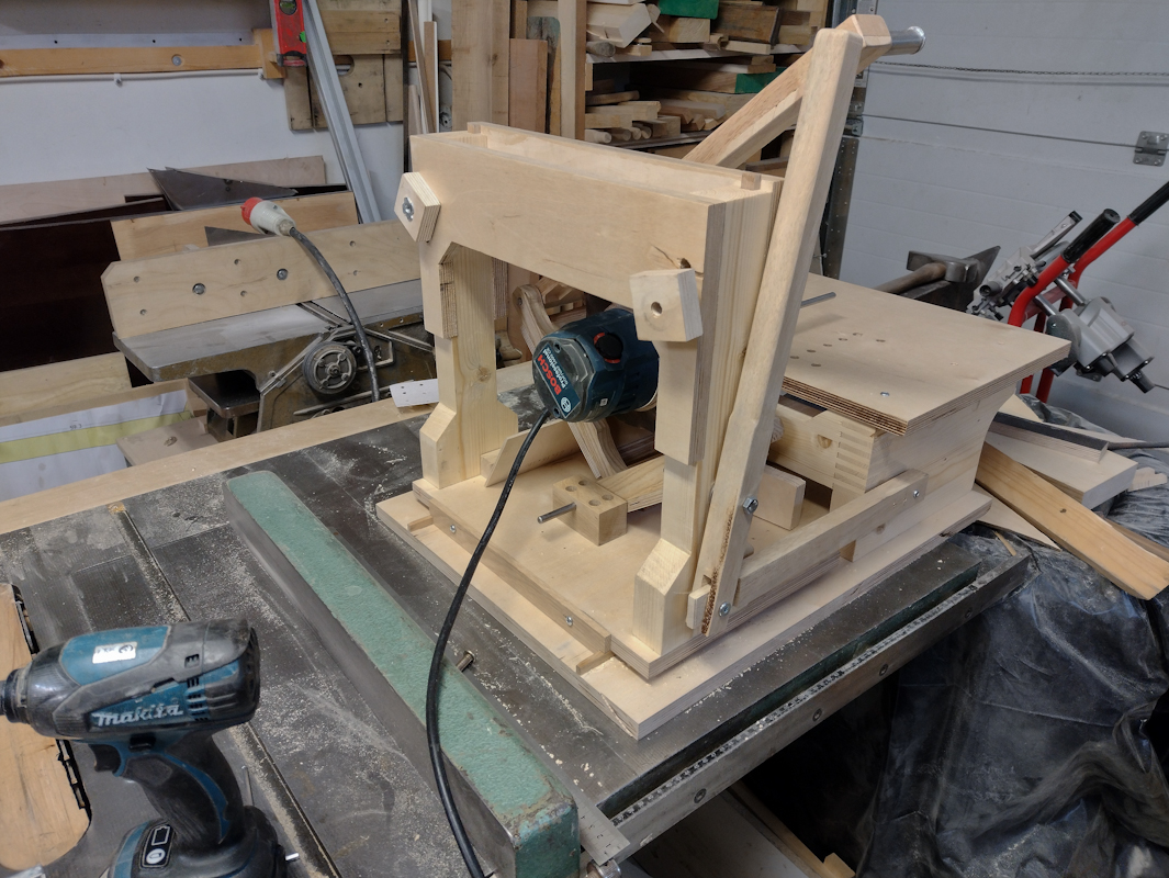
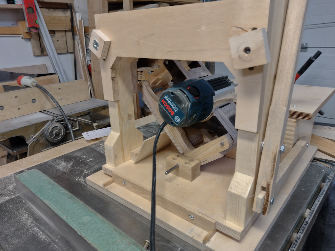
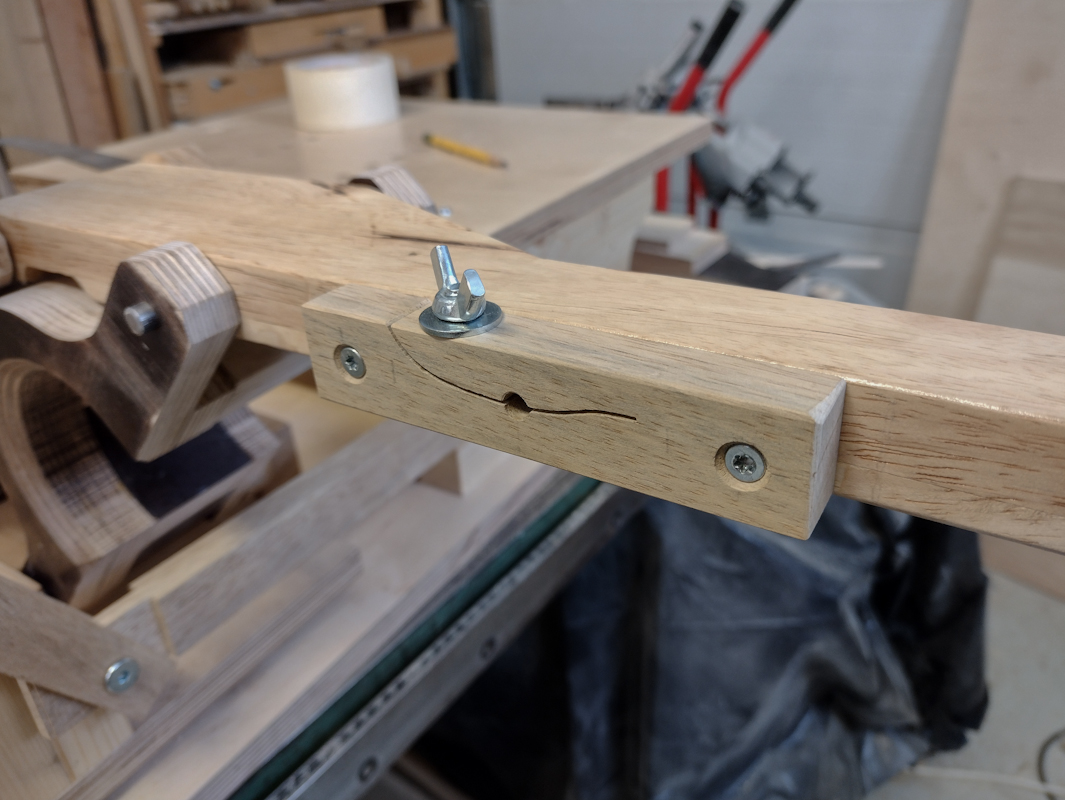
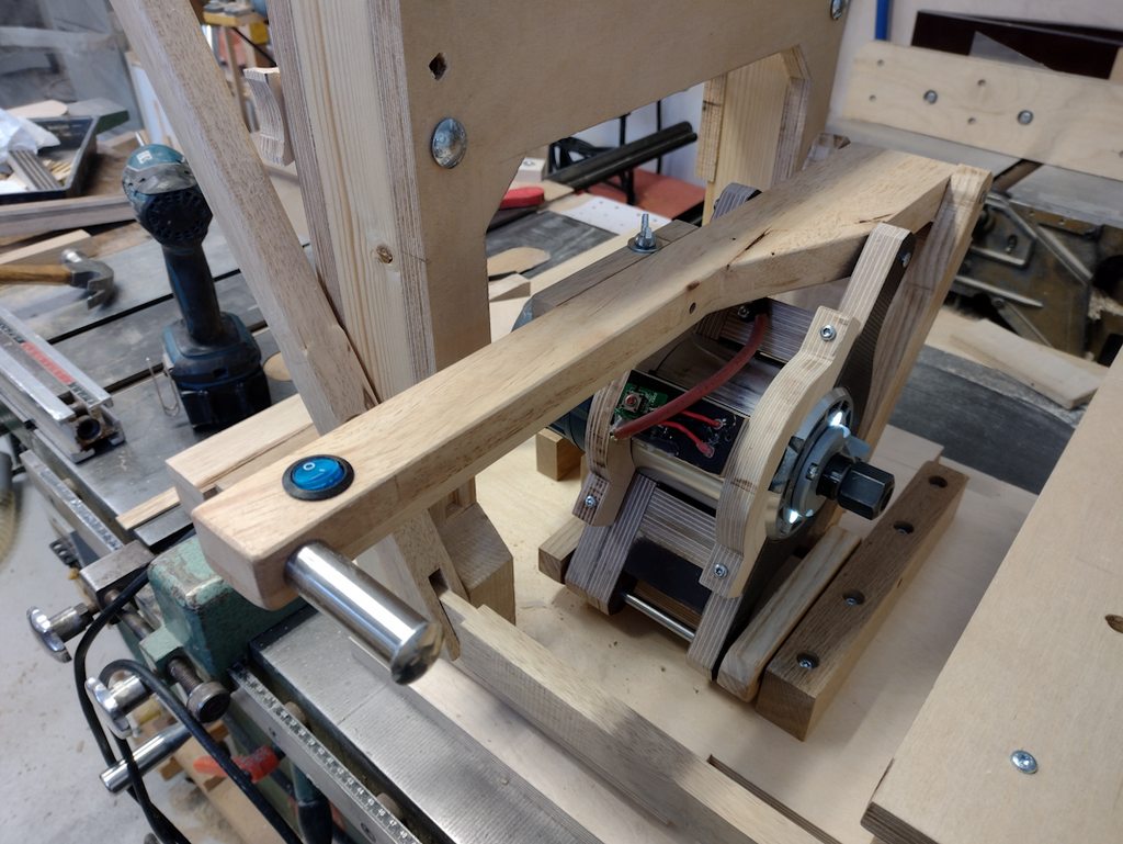
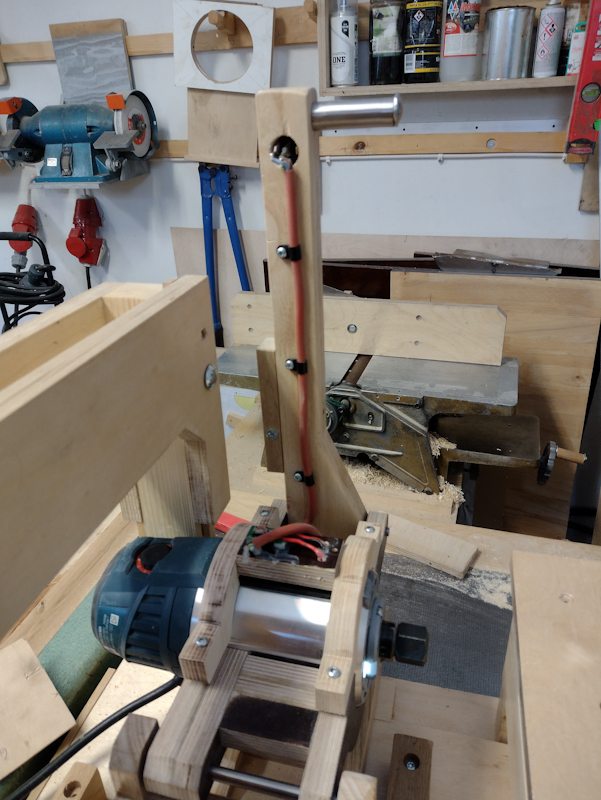
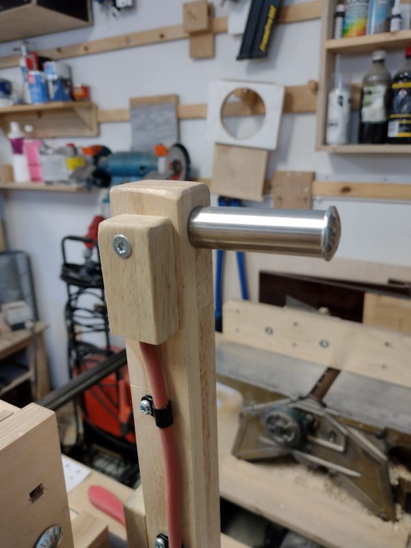
After that I made the handle and test fitted the pantograph mechanism
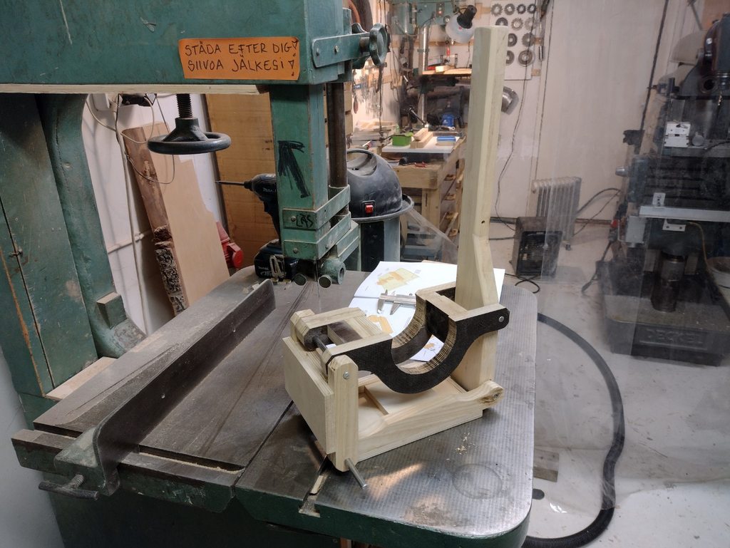
And that is how far I've gotten.
Well I'm starting it back up now. Last time I cut the outside of the three templates and drilled the holes. I used double sided tape to tape them all together so I could drill and cut them all as one part, in order to make it easier to keep the parts accurate.
The big piece of plywood is the base. Not sure about using this film plywood but it's all I got. Still gonna have to buy more.


Moving on the long links, I am going to use my most accurate tool to lay out and dril the holes. My milling machine and DRO. I am going to make two links but I will do all the work on a single overly thick piece, then I'll rip the part on the table saw into two thinner pieces. That way I should get two identical parts. The accuracy of the links in the pantograph is the most critical part. I have an endmill that makes a little too tight of a fit for the 8mm shafting I am using, but this is good, that means I can ream to size using a reamer made from the shafting I will be using.

Long link assembled without glue:

Matthias updated his plans in 2018 and made refinements to the machine. I am working from the original plans, but I will include the updates he made since they are gneuine improvements, I also have ideas of my own modifications. This part above has been simplied in design in the newer machine but functionally it's the same, I made it according to the old design.
Gluing up parts, doing it in stages or the parts will move and it will be impossible to get straight.

When I glue up the last component of the links and router holder I put the shafting in to properly orient everything. I then rested the links on two pieces of wood that is the same height before clamping up. That way all the links would be planar to each other and I avoid twist. Unfortunately this part must have moved anyway and it had a lot of twist (0.2mm). I mounted it in the mill and corrected the hole, but now it is oval:

After that the twist was only a few hundreths which is good enough

But the hole cannot be left oval so I fill the gap with epoxy and let it dry in place. I waxed the shafts so the epoxy doesn't stick to them.

After that I made the handle and test fitted the pantograph mechanism

And that is how far I've gotten.


