Newts 'Y' Lever

UKworkshop.co.uk

Help Support UKworkshop.co.uk:

This site may earn a commission from merchant affiliate links, including eBay, Amazon, and others.

woodbloke

Established Member
Joined
13 Apr 2006
Messages
11,770
Reaction score
1
Location
Salisbury, UK
Pete's (Newt) been over this afternoon for a natter and brought his 'Y' lever over for me to have a look at. It's been machined from a block of solid brass similar to the one in the pic and it took him about a day to do it. In our natterings we both agreed that there is far more thinking than doing time when you make something really complicated, as this is:
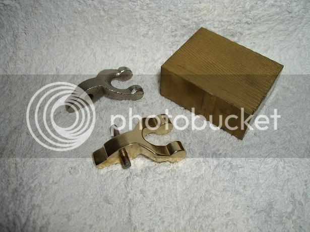
33s22c2dc2.jpg


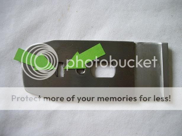
Pete also found that by relieving the back of the slot in the chipbreaker just a fraction by rounding over slightly with a needle file makes a very big difference in the ease wih which the blade can be retracted and moved forward....I found that a spot of grease on the bearing surfaces also helped a bit more:
mlammmdm.jpg


The green arrows show the corner I'm on about, the pic shows the reverse side of a Clifton cap iron with the slight relieving having been done. We also had a natter about the merits of BU planes and I realized (and Pete was in firm agreement) the reason that they are so good is that the blade can be supported almost the the cutting edge by the bed, something that is impossible on a normal BD design.
Paul - your Record No4 already has this little cap iron mod done -Rob
 
Great pictures, Rob. And Pete, that's an incredibly good-looking Y-lever. Your metalworking skills are gobsmacking :D Thanks for doing the mod on the cap iron Rob :wink:

Cheers :wink:

Paul
 
woodbloke":1e979i0a said:
Pete's (Newt) been over this afternoon for a natter and brought his 'Y' lever over for me to have a look at. It's been machined from a block of solid brass

Yikes! and ... wow! That's crazy, and yet strangely impressive...

Pete also found that by relieving the back of the slot in the chipbreaker just a fraction by rounding over slightly with a needle file makes a very big difference in the ease wih which the blade can be retracted and moved forward....I found that a spot of grease on the bearing surfaces also helped a bit more:

Abso-smegging-lutely. The depth adjustment on a Bailey plane involves quite a lot of bearings and contact points that all need to slide. A small amount of attention to each surface (essentially make sure they're smooth/flat/lubricated as appropriate) can help a great deal.

One of my favourite little tricks is to smooth the surface of the cam of the lever cap (where it rubs on the spring). This can make the action of the lever cap dramatically nicer.

BugBear
 
Making 51 I will try. It may be a good idea to identify the parts: the part that engages with the iron lets call the engagement peg (EP), the shaft that connects to the Peg, peg Shaft (PS), the outer shoulders (OS)of the Y that join into the PS, the 2 circular parts that engage with the adjustment knob (CP) and finally the horse shoe shaped opening (SO).

All the work is done with 2 sized end mills 15mm and 10mm. The sequence of milling is important as the shape could make work holding in the vice difficult.
Mill the block to the overall dimensions leaving a bit extra at the EP end, mark out on the block the overall shape both in plan and side elevation, scribe the CP. First mill the 2 OS's and the PS, hold in the vice by PS and mill the the top and bottom of basic shape looking from the side (as if you were looking at the side of the plane with the Y lever installed), mark the position of the pivot hole and drill. Mill the basic shape of the CP's by holding in the vice by the PS and rotating in the vice after each pass to produce a series of facets that are tangental to the CP scribed circles, this is the hard bit. Roughly mill the EP taking care that it has the form of a gear tooth, I leave this longer than the original so I can use a thicker blade. Finally holding in the vice by PS mill the SO. With a fine file blend all the contours taking great care that the CP, are truly circular and fit he adjustment wheel with a snug fit. Fit the Y lever to the plane and try and engage the blade and iron, mark the EP surface with black marking ink and press on the iron and carefully file the contact points but retaining the shape of a gear tooth, stop when the iron sits flush on the frog and the adjustment knob operates smoothly over its range. Remove Y lever file away all sharp edges, smooth all surfaces with fine wet and dry, be careful with EP and CP. Apply some dry lube to contact parts and your done. Not a very quick description, hope you did not fall asleep to quick. I have about one third of a turn of free play in the adjusment knob, the original had two and a half turns.
 
Back
Top