1. Introduction
One of the items missing from my workshop is a large flat work surface that can be used for assembly and fabrication. I have a wooden Sjöbergs workbench, but want to reserve it for hand tool use. It's location makes it of limited use since it is against the wall and I can't access it from the far side. My wife saw me struggling with one project and asked how I planned on building her bookshelves in such a small shop.
After a bit of discussion and brainstorming, we agreed that I could rearrange the basement and have the second 5x5 meter part that is adjacent to my shop. This would become my office, assembly area, hobby corner...man shed. While this will create maneuvering space, I still needed and assembly table. All of the powered equipment that produces lots of dust and connects to the large dust collection system will remain in the original shop, but the Sjöbergs bench, hand tools, drill press and smaller equipment that connects to the CT-36 vacuum will move to the other side.
I saw a thread on the Festool Owners Group (FOG) by AtomicRyan, where he documented his construction of a mobile workbench that uses a full sheet of 3/4-inch MDF for the top and aluminum extrusion for the frame. [Note: I will use the American English spelling of the 13th element in the Periodic Table of the Elements throughout this thread, as well as other words, so no corrections please. ]
]
Ryan called his project the BF/MFT Build. In addition to the thread on FOG, Ryan uploaded four construction videos to his YouTube site, The Garage Journal.
Here is the first of the four videos describing his construction, as well as the problems he had with the CNC shops making the 20mm dog holes in the MDF sheet.
Figure 1.1: YouTube video Part 1 of 4 from The Garage Journal
After watching these videos, I knew I wanted to build a smaller version of the BF/MFT. My MFT-style workbench would be 1x2 meters and would have some storage for my commonly used Festool equipment and layout tools. I watched Ryan's videos several times and made notes of his mistakes and lessons learned so I could avoid them, or at least try.
Ryan used the 8020 aluminum extrusion that is available in the U.S., but difficult to find in Germany. However, there is a similar source in Germany called item24 that has a great assortment of material, as well as an online engineering tool to design anything from their inventory of parts. The UK affiliate is Machine Building Systems in Ripley.
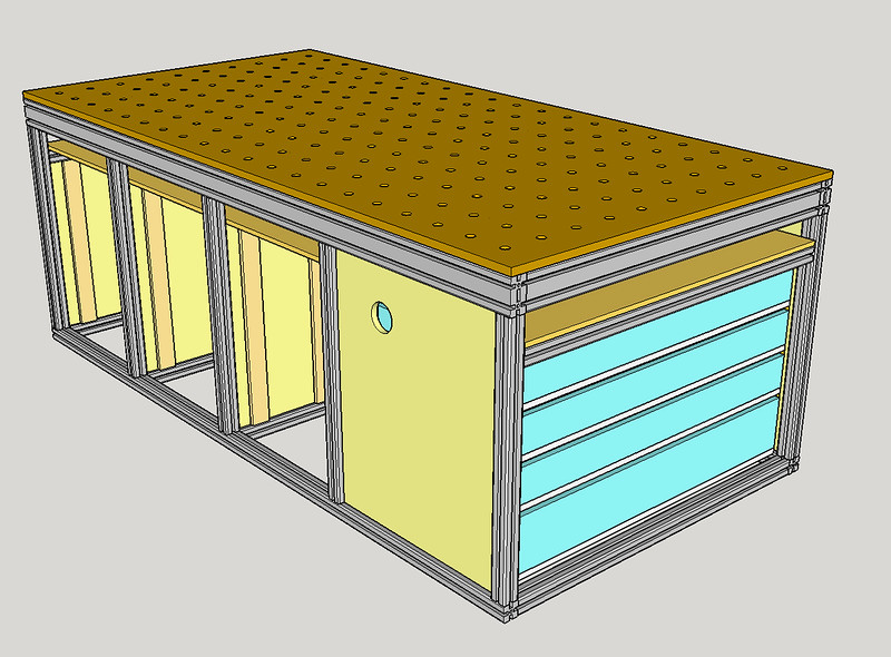
The item24 engineering tool is cumbersome to use at first and lacks the sophistication of AutoCAD, but it works and is part of the item24 enterprise that integrates the sales, machining, packaging, and shipping departments. I was able to design this workbench in about an hour and rotate it around in 3D space before going to the next step and creating detailed engineering drawings.
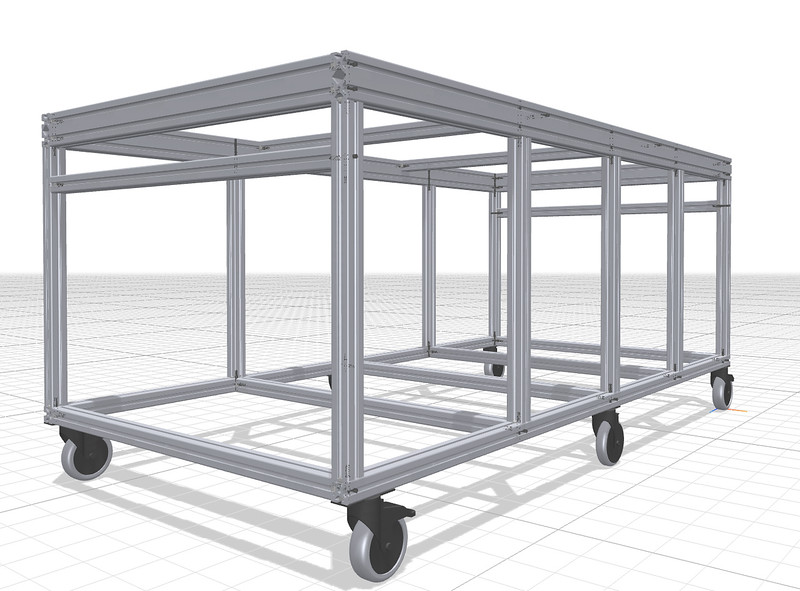
Figure 1.2: Screenshot from item24 engineering application
As each piece of aluminum is added to the drawing, the software automatically identifies the drill points, adds the hardware to join the item, identifies the thread size for tapping, and builds the bill of material (BOM). For example, when I selected the locking castor and attached it to the bottom of the frame, the software automatically added the two M8 screws and T-nuts to the BOM. When one of the 920mm sections of extrusion was attached, the software added the standard clip and M8 screw, M8 threads for the screw, and 7mm through hole for the hex key access in the adjoining part. If I moved this part along the other piece, the holes moved with it. The parts count was updating as I added new material, and I was able to make quick QC checks during the design. In a couple of places, the vertical sections didn’t register with the horizontal section, and I could verify this because the mounting hardware count didn’t increment as it should. A quick digital jiggle of the part, and it joined correctly and the parts count incremented.
When I was satisfied with the design, I went to the next step to create the build package that would be used by item24 to develop the cost. The output of this process was a 26-page PDF created by the engineering software. I downloaded the file to perform a thorough QC of the workbench and found two more areas that had not correctly joined each other. It was easy to go back, make the correction, and continue. The PDF included the manufacturing sheets for each piece of 40x40mm and 80x40mm extrusion, dimensions for the CNC cutting and drilling, an exploded view of the workbench, and step by step assembly instructions unique to my design.
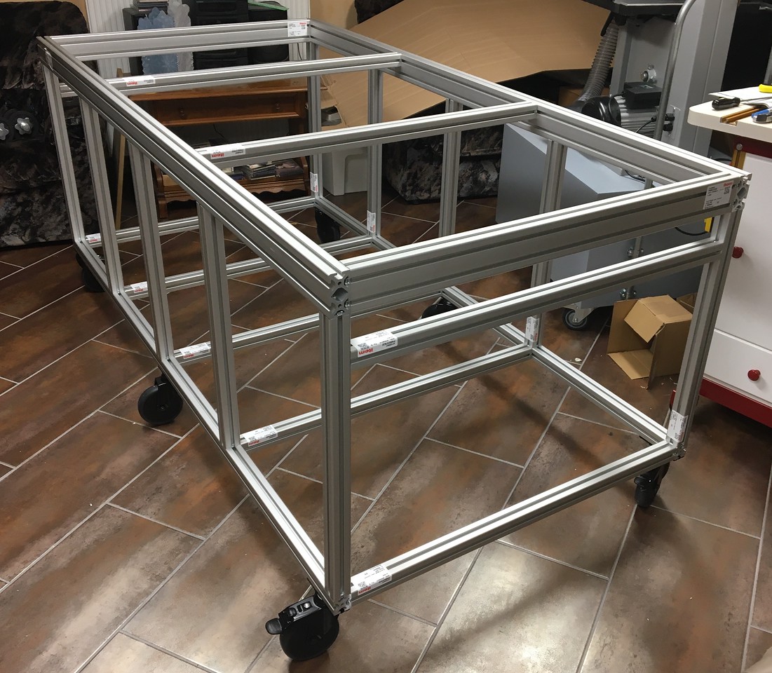
Here is one of the pages from the 26-page PDF that shows the exploded view of the workbench frame as designed and ordered. I later added two more horizontal pieces (part number 3v) to support the top.
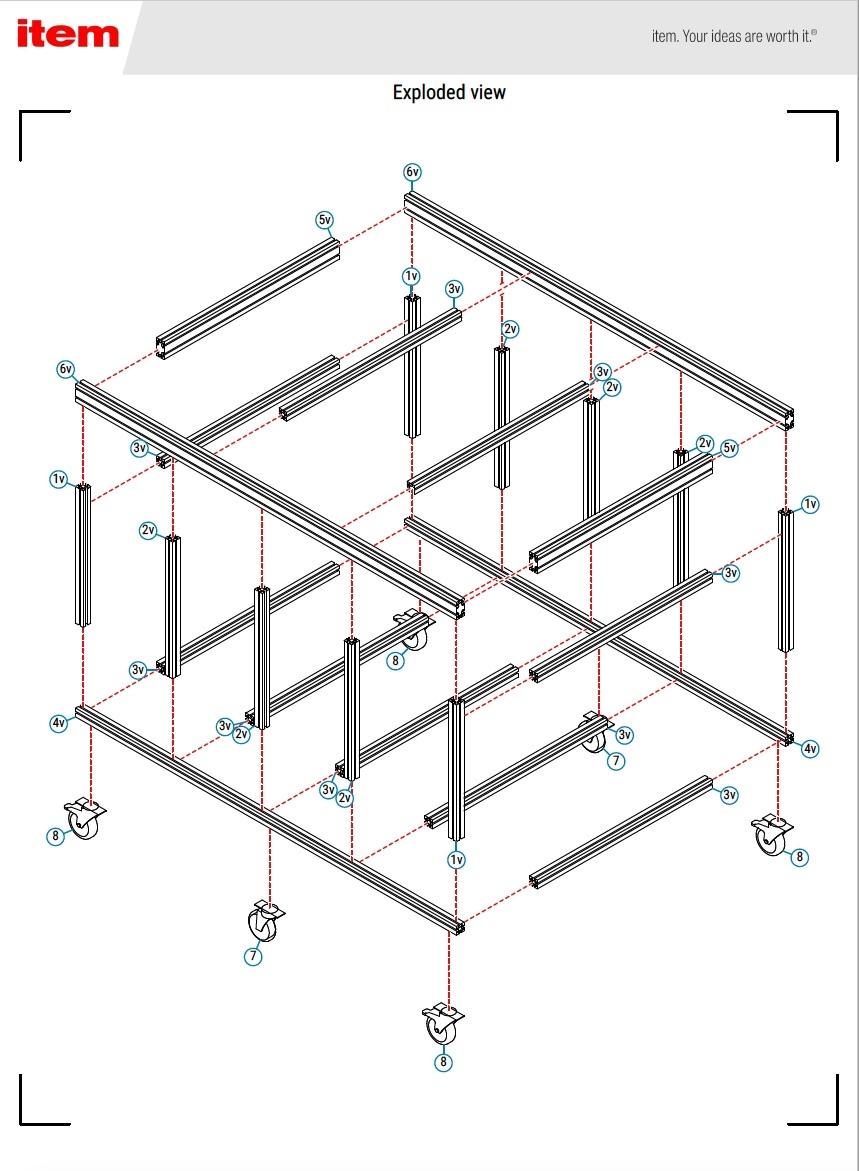
Figure 1.3: Sample page from item24 engineering PDF
My cost for the complete kit as shown, plus some extra T-nuts and screws, was €1,460 (about £1,307 today), which included VAT and shipping. This does not include the cost for the 19mm Valchromat top, 10mm plywood shelf, 12 and 15mm plywood for drawers, shelves, and partitions, the drawer slides and other assorted hardware. I could have bought the extrusion in 3-meter sections and done all of the cutting, drilling, and tapping myself, but this is something I am quite comfortable paying for and letting someone else deal with the cleanup.
To give an idea of the flash to bang on this part of the project, here is the timeline for the first order from item24:
6 October 2020: Submitted online design
7 October 2020: Received confirmation from item24 with the formal offer
7 October 2020: I confirmed the offer and submitted a second request for additional hardware (screws and T-nuts)
8 October 2020: Received confirmation from item24 with the formal offer on the additional hardware
8 October 2020: I confirmed the offer and requested the extra hardware be included with the first order
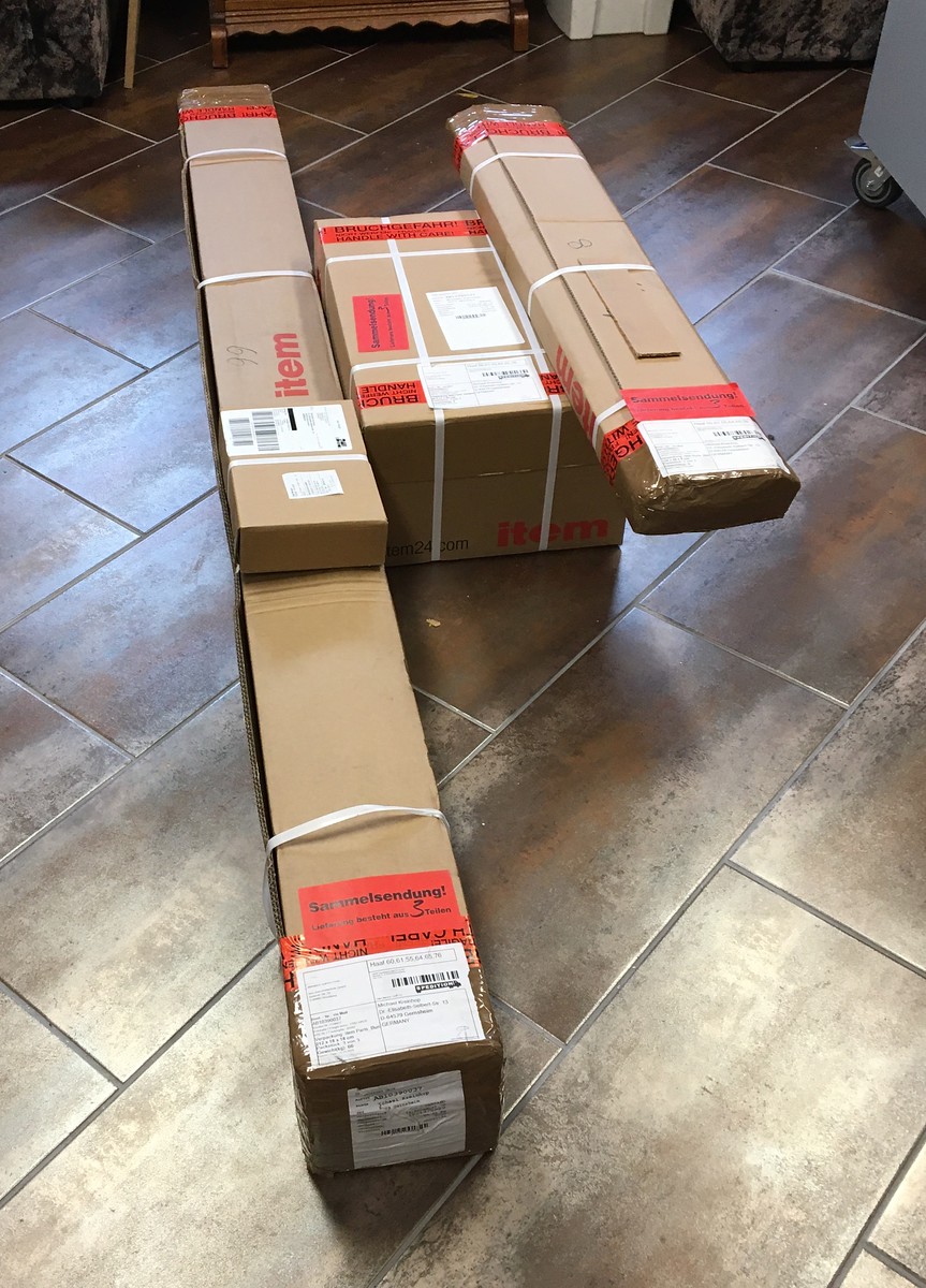
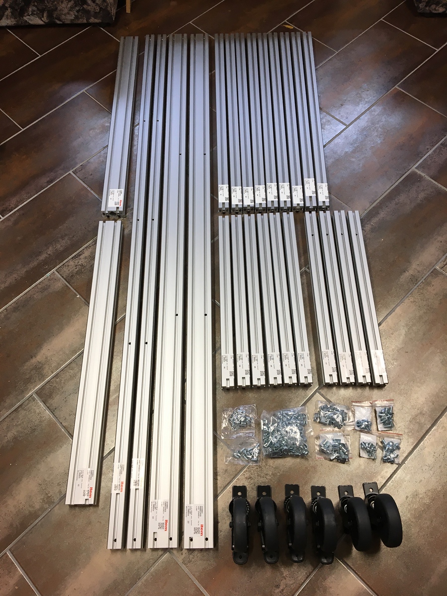
14 October 2020: Shipment of four packages from item24 received!
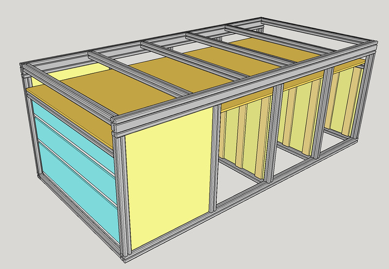
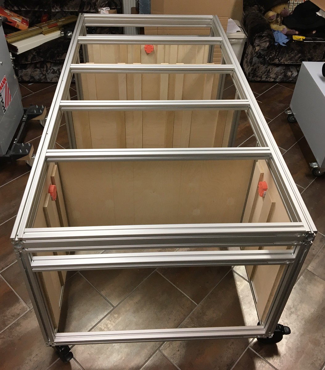
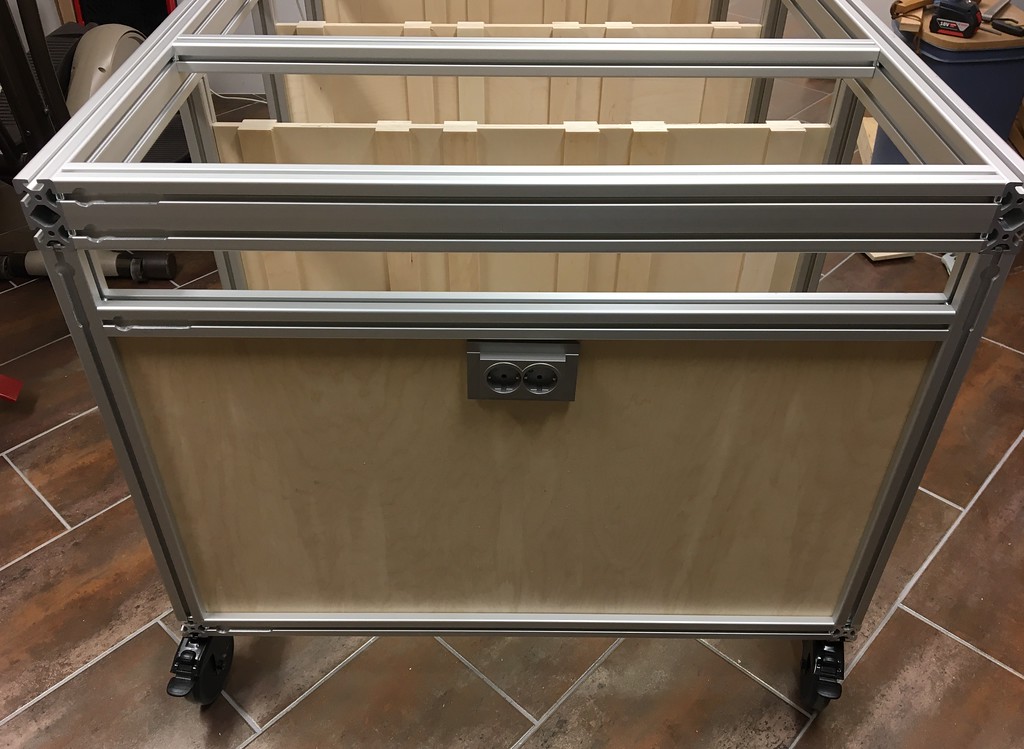
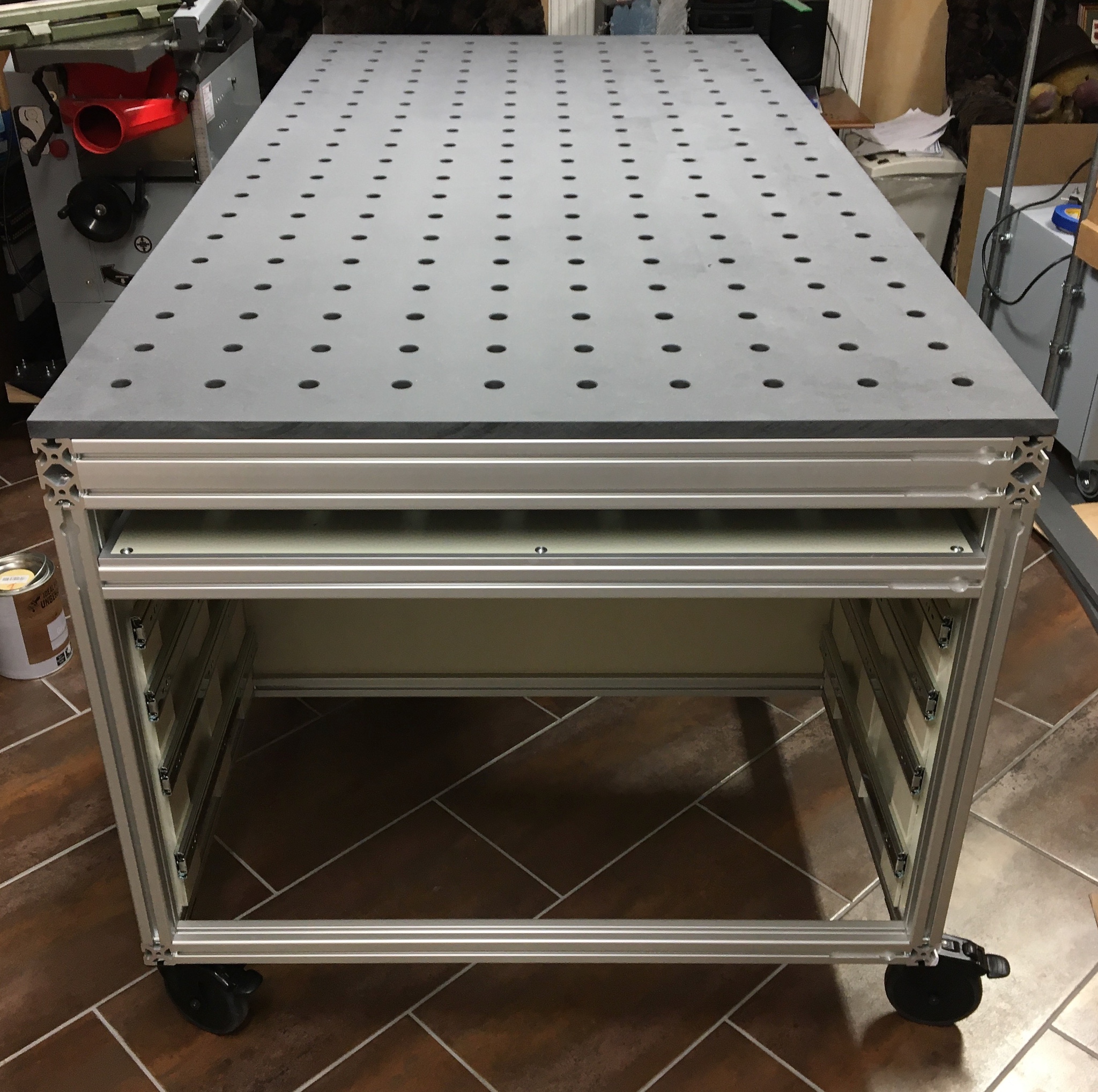
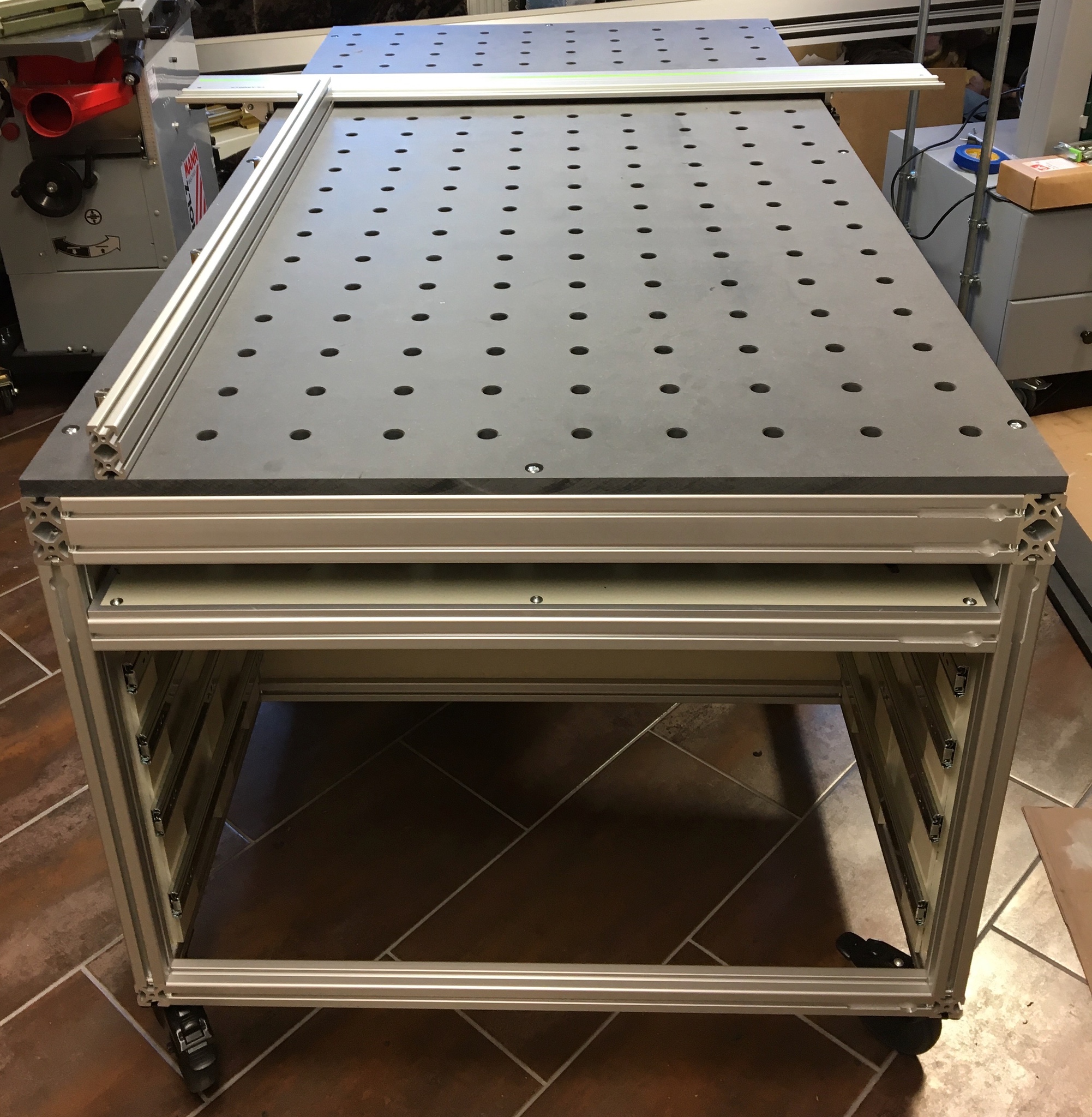
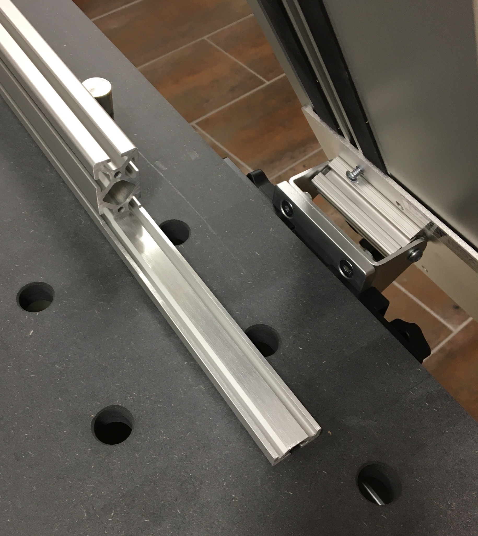
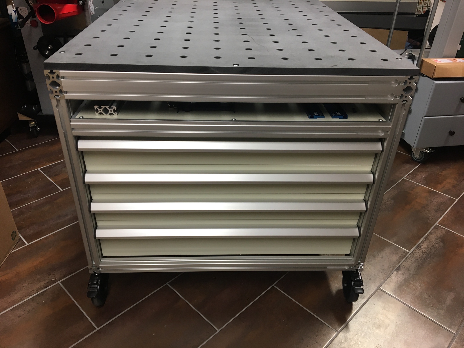
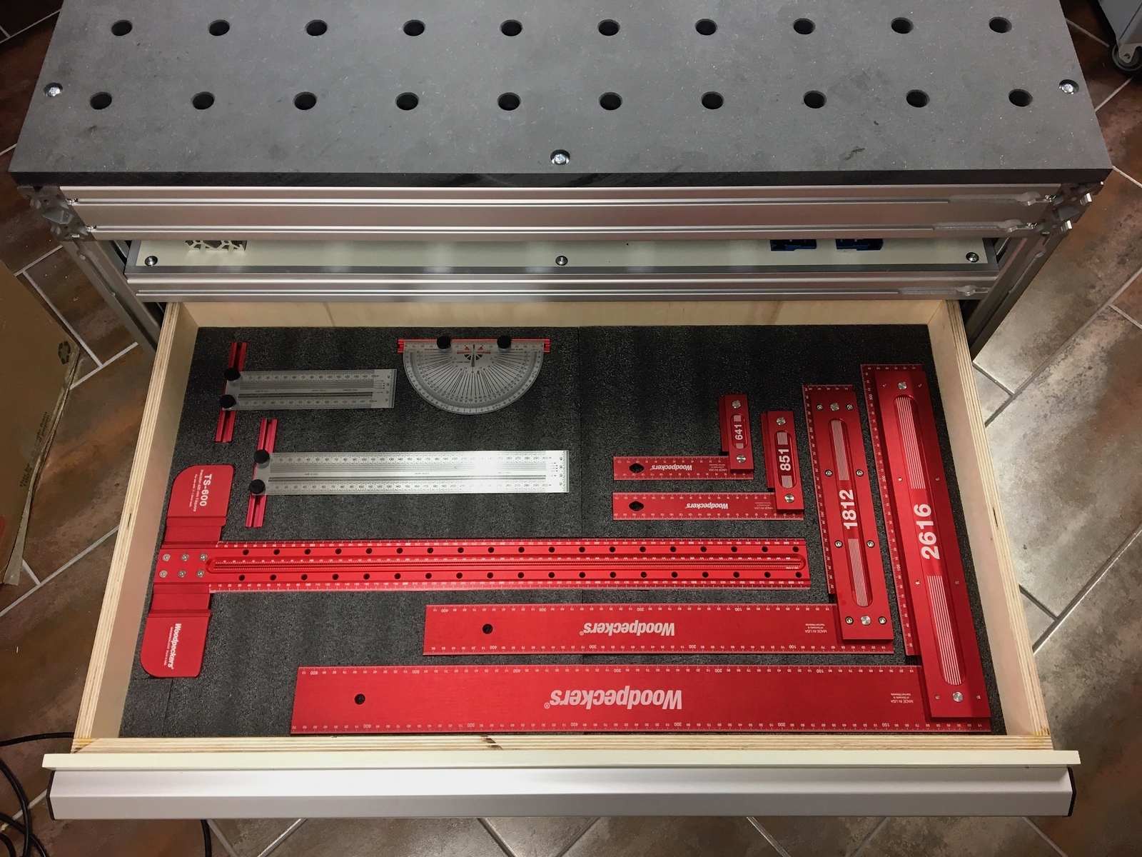
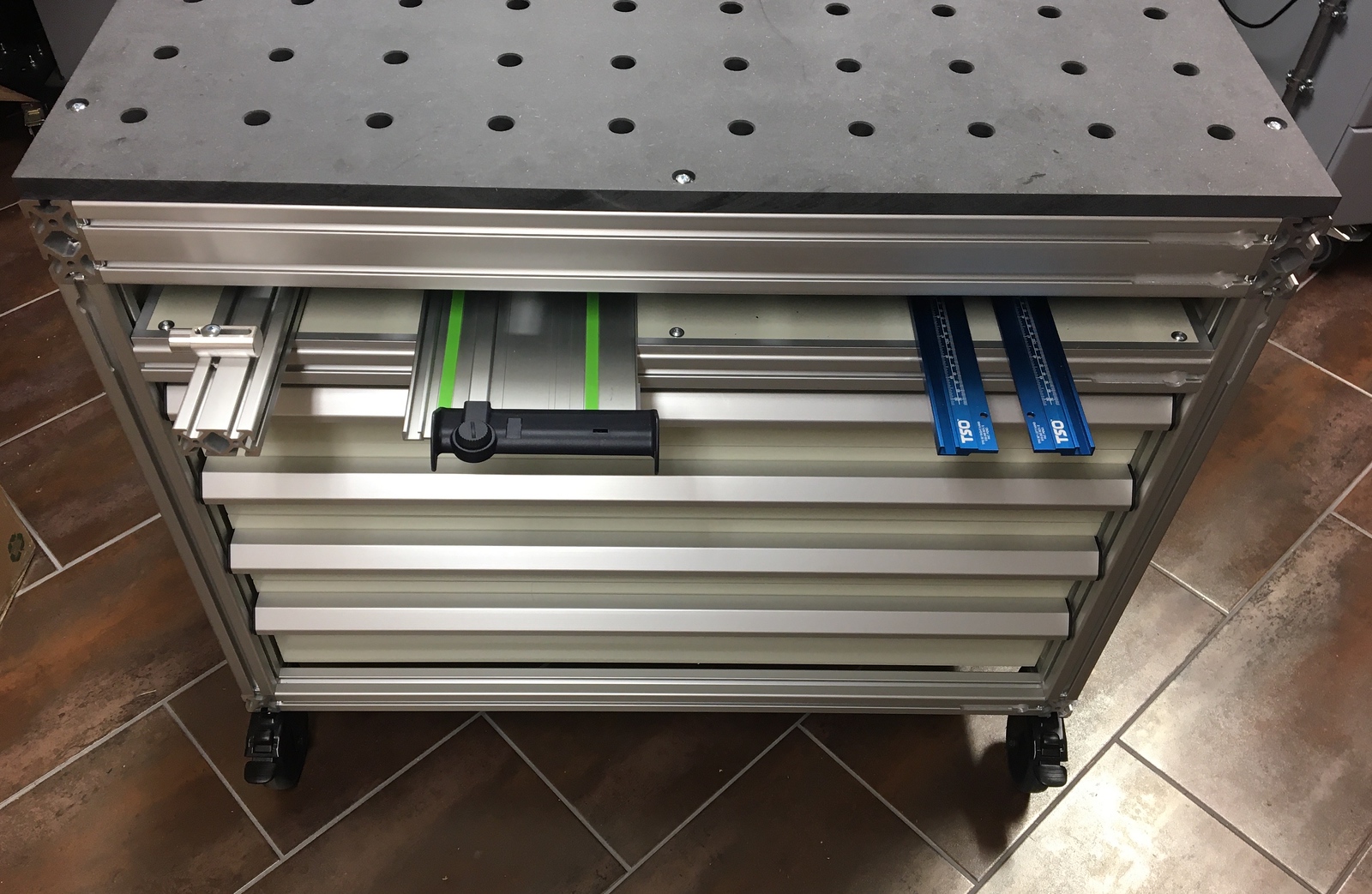
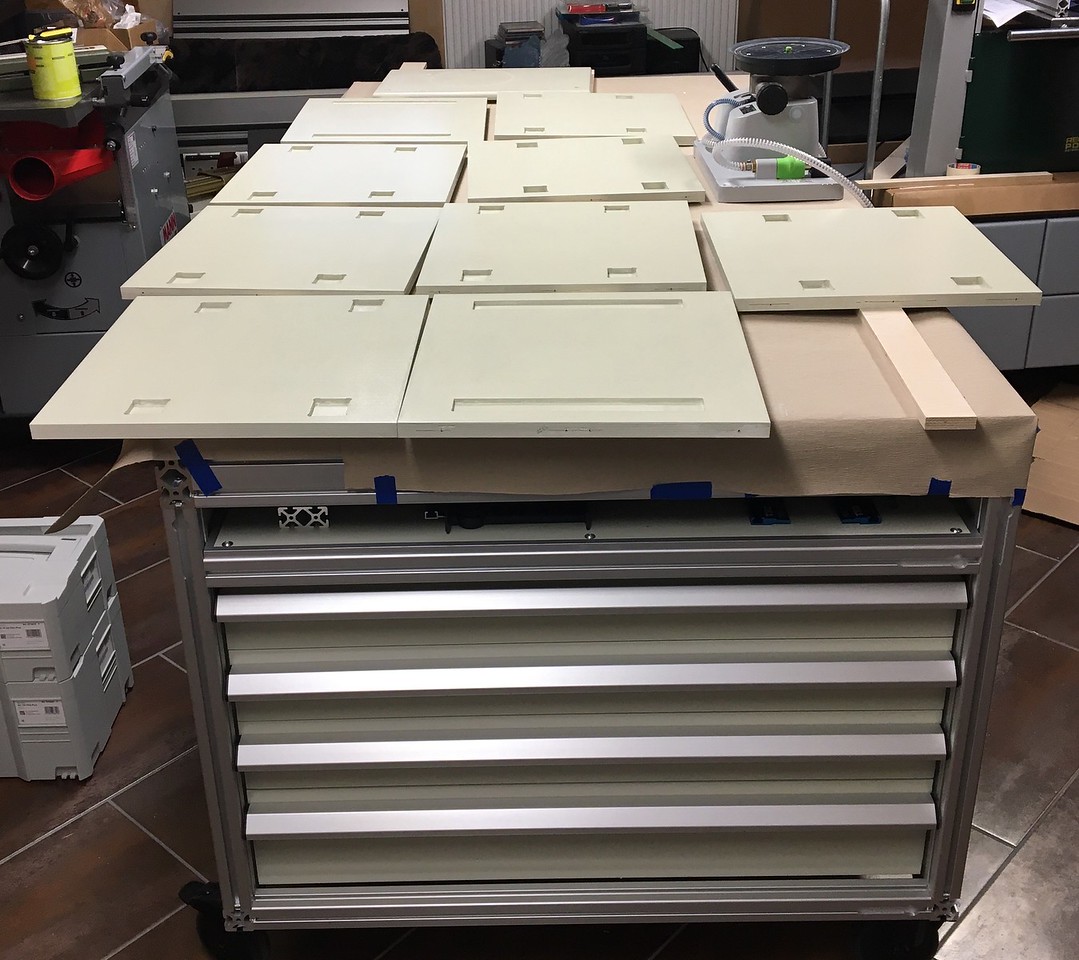
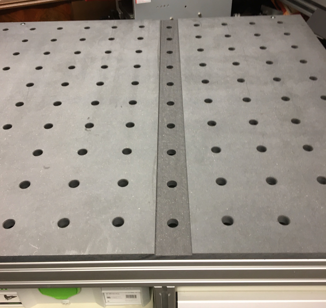
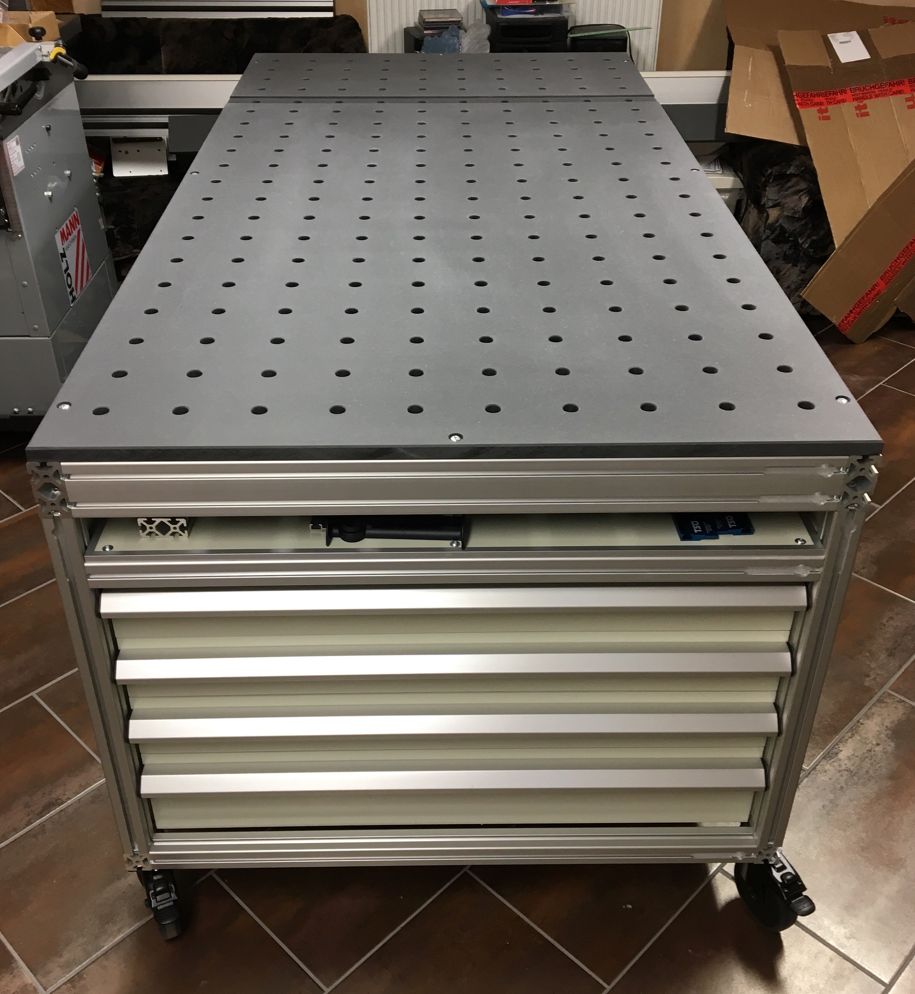
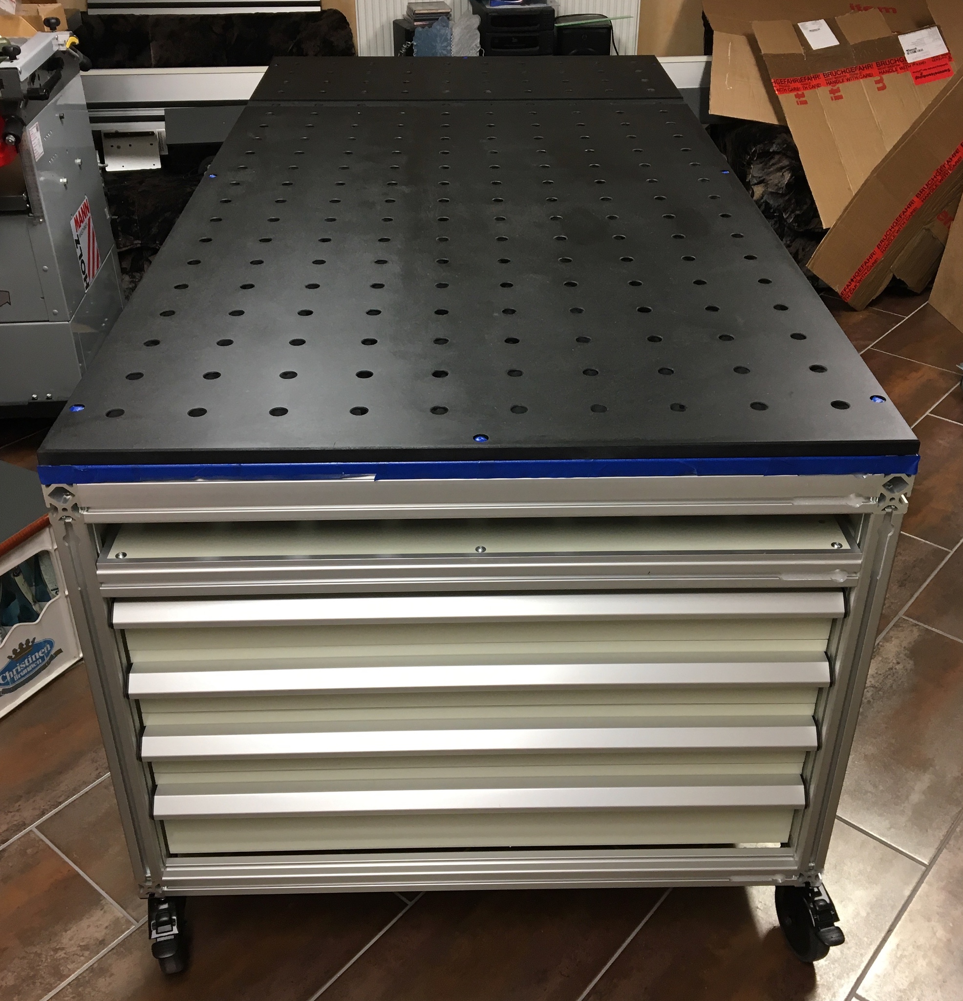
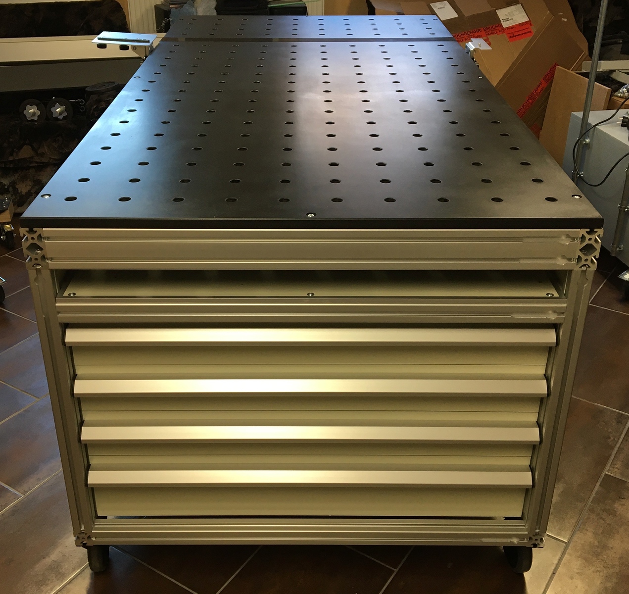
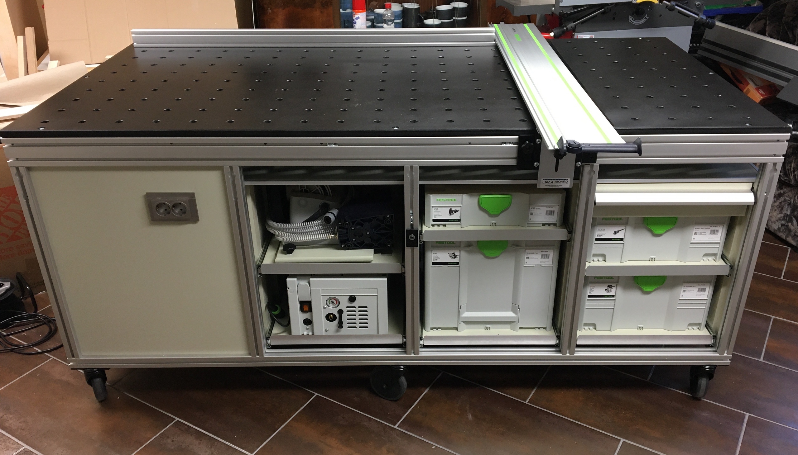
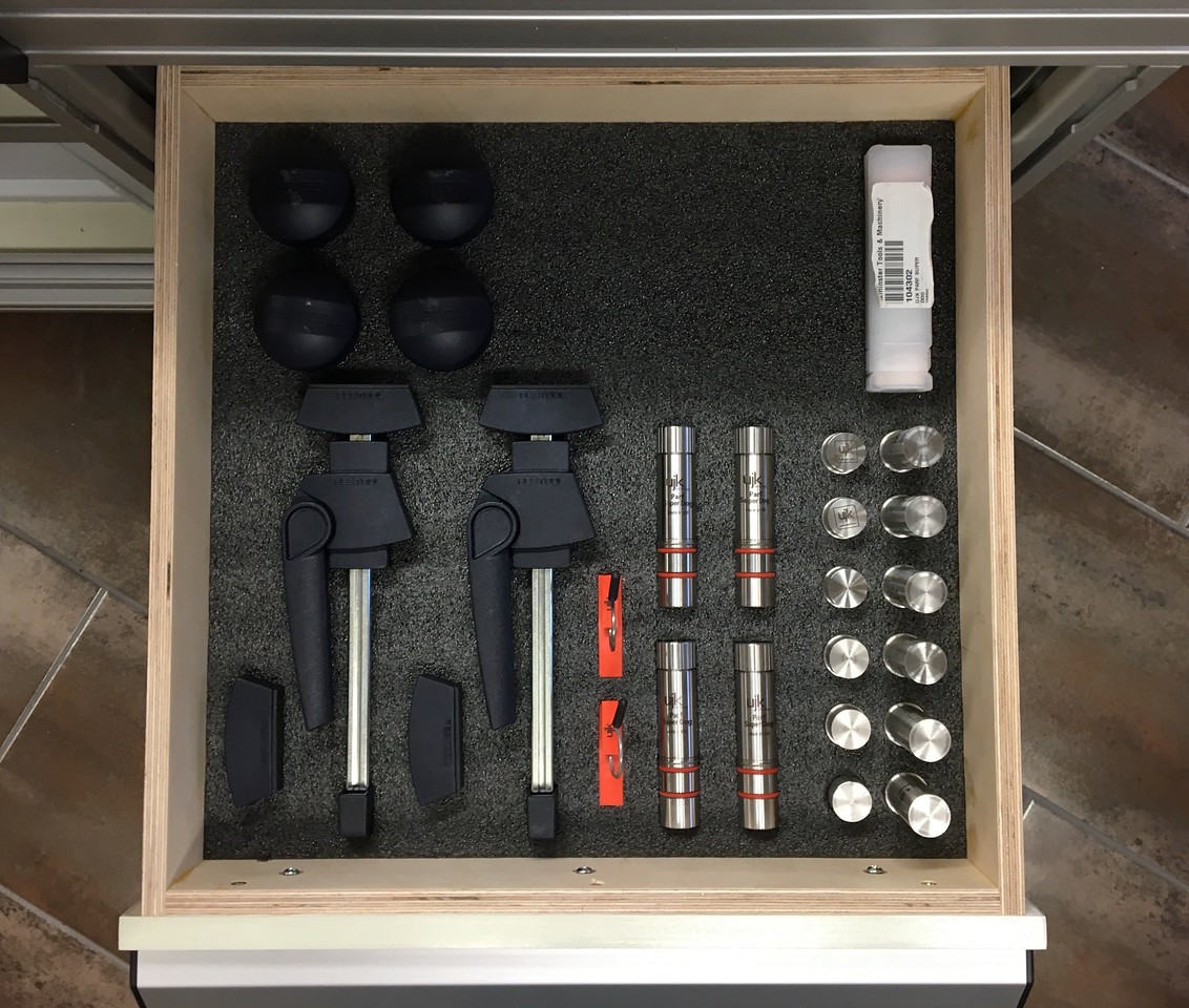
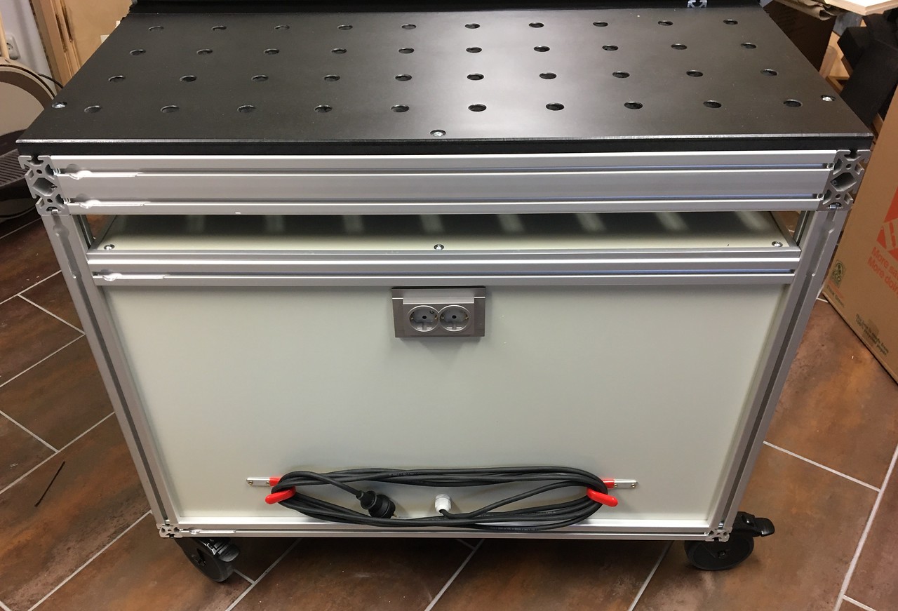
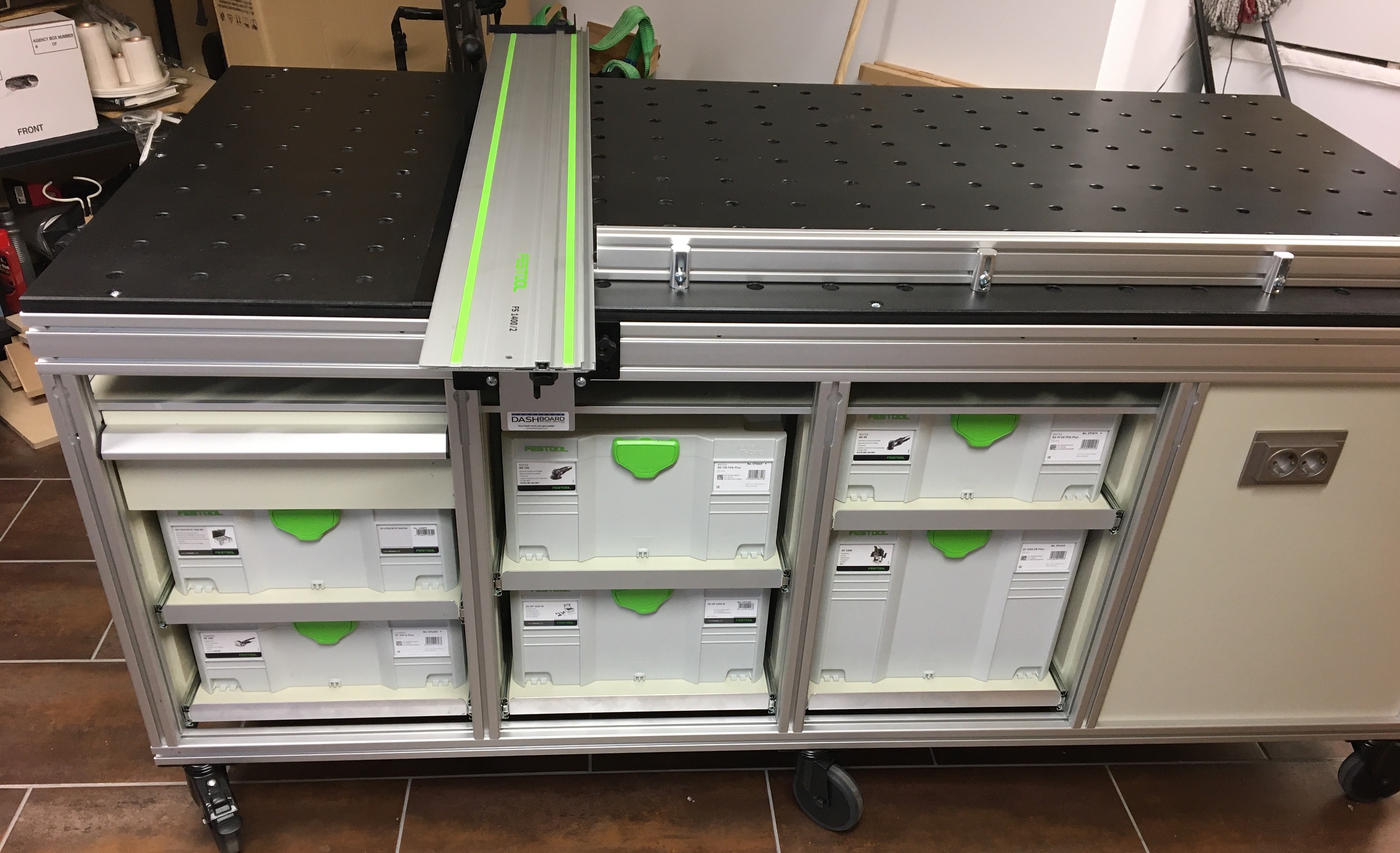
Now the fun begins...but first, here is the final product.

Figure 1.4: Photo of completed workbench
One of the items missing from my workshop is a large flat work surface that can be used for assembly and fabrication. I have a wooden Sjöbergs workbench, but want to reserve it for hand tool use. It's location makes it of limited use since it is against the wall and I can't access it from the far side. My wife saw me struggling with one project and asked how I planned on building her bookshelves in such a small shop.
After a bit of discussion and brainstorming, we agreed that I could rearrange the basement and have the second 5x5 meter part that is adjacent to my shop. This would become my office, assembly area, hobby corner...man shed. While this will create maneuvering space, I still needed and assembly table. All of the powered equipment that produces lots of dust and connects to the large dust collection system will remain in the original shop, but the Sjöbergs bench, hand tools, drill press and smaller equipment that connects to the CT-36 vacuum will move to the other side.
I saw a thread on the Festool Owners Group (FOG) by AtomicRyan, where he documented his construction of a mobile workbench that uses a full sheet of 3/4-inch MDF for the top and aluminum extrusion for the frame. [Note: I will use the American English spelling of the 13th element in the Periodic Table of the Elements throughout this thread, as well as other words, so no corrections please.
Ryan called his project the BF/MFT Build. In addition to the thread on FOG, Ryan uploaded four construction videos to his YouTube site, The Garage Journal.
Here is the first of the four videos describing his construction, as well as the problems he had with the CNC shops making the 20mm dog holes in the MDF sheet.
Figure 1.1: YouTube video Part 1 of 4 from The Garage Journal
After watching these videos, I knew I wanted to build a smaller version of the BF/MFT. My MFT-style workbench would be 1x2 meters and would have some storage for my commonly used Festool equipment and layout tools. I watched Ryan's videos several times and made notes of his mistakes and lessons learned so I could avoid them, or at least try.
Ryan used the 8020 aluminum extrusion that is available in the U.S., but difficult to find in Germany. However, there is a similar source in Germany called item24 that has a great assortment of material, as well as an online engineering tool to design anything from their inventory of parts. The UK affiliate is Machine Building Systems in Ripley.
The item24 engineering tool is cumbersome to use at first and lacks the sophistication of AutoCAD, but it works and is part of the item24 enterprise that integrates the sales, machining, packaging, and shipping departments. I was able to design this workbench in about an hour and rotate it around in 3D space before going to the next step and creating detailed engineering drawings.

Figure 1.2: Screenshot from item24 engineering application
As each piece of aluminum is added to the drawing, the software automatically identifies the drill points, adds the hardware to join the item, identifies the thread size for tapping, and builds the bill of material (BOM). For example, when I selected the locking castor and attached it to the bottom of the frame, the software automatically added the two M8 screws and T-nuts to the BOM. When one of the 920mm sections of extrusion was attached, the software added the standard clip and M8 screw, M8 threads for the screw, and 7mm through hole for the hex key access in the adjoining part. If I moved this part along the other piece, the holes moved with it. The parts count was updating as I added new material, and I was able to make quick QC checks during the design. In a couple of places, the vertical sections didn’t register with the horizontal section, and I could verify this because the mounting hardware count didn’t increment as it should. A quick digital jiggle of the part, and it joined correctly and the parts count incremented.
When I was satisfied with the design, I went to the next step to create the build package that would be used by item24 to develop the cost. The output of this process was a 26-page PDF created by the engineering software. I downloaded the file to perform a thorough QC of the workbench and found two more areas that had not correctly joined each other. It was easy to go back, make the correction, and continue. The PDF included the manufacturing sheets for each piece of 40x40mm and 80x40mm extrusion, dimensions for the CNC cutting and drilling, an exploded view of the workbench, and step by step assembly instructions unique to my design.
Here is one of the pages from the 26-page PDF that shows the exploded view of the workbench frame as designed and ordered. I later added two more horizontal pieces (part number 3v) to support the top.

Figure 1.3: Sample page from item24 engineering PDF
My cost for the complete kit as shown, plus some extra T-nuts and screws, was €1,460 (about £1,307 today), which included VAT and shipping. This does not include the cost for the 19mm Valchromat top, 10mm plywood shelf, 12 and 15mm plywood for drawers, shelves, and partitions, the drawer slides and other assorted hardware. I could have bought the extrusion in 3-meter sections and done all of the cutting, drilling, and tapping myself, but this is something I am quite comfortable paying for and letting someone else deal with the cleanup.
To give an idea of the flash to bang on this part of the project, here is the timeline for the first order from item24:
6 October 2020: Submitted online design
7 October 2020: Received confirmation from item24 with the formal offer
7 October 2020: I confirmed the offer and submitted a second request for additional hardware (screws and T-nuts)
8 October 2020: Received confirmation from item24 with the formal offer on the additional hardware
8 October 2020: I confirmed the offer and requested the extra hardware be included with the first order
14 October 2020: Shipment of four packages from item24 received!
Now the fun begins...but first, here is the final product.

Figure 1.4: Photo of completed workbench
Attachments
Last edited:


