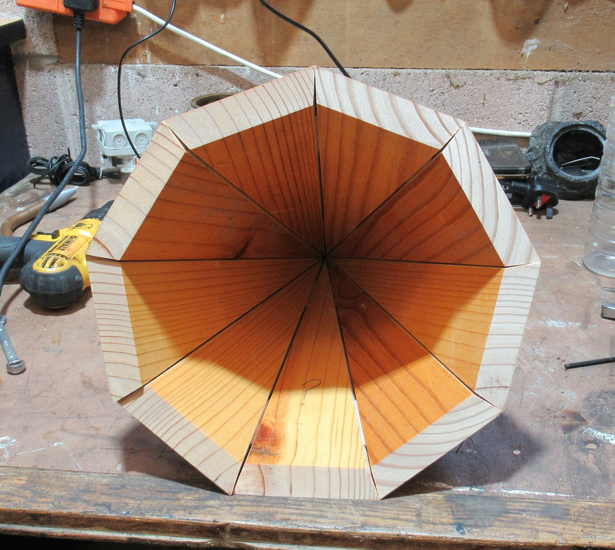
How do I calculate these angles?

UKworkshop.co.uk

Help Support UKworkshop.co.uk:

This site may earn a commission from merchant affiliate links, including eBay, Amazon, and others.
My 'mathemaical' solution - from first principles - took me less than 30 minutes. It'll probably take you longer than that to set your drawing board up !!
I just did a rough sketch just to remind myself. I reckon 5 to 10 minutes.
I'll do a nice clear version tomorrow.
The principle of graphic projections is to see each of the components as a hollow box. From the basic plan and elevation drawing you then project on to paper the various dimensions as though unfolding the boxes and laying them flat in the same plane. Been used for millennia.
 
Last edited:
Wrong.
This happens to be a very simple roof structure and graphic projections are the ancient, classical well established non mathematical way of working out roof structures particularly, and other things too. And it can be a lot faster.
I'll do a demo tomorrow, can't be bothered to get the drawing board out now.
It used to feature in all the old books and was taught until relatively recently. Not entirely forgotten - it's too useful, but dropped right off the radar of the new boys! A bit like sharpening really. :ROFLMAO:

I recently got a new 12" adjustable roofing square ( by tracer ) as my 2nd stanley got pinched ( same as the first ) years ago and they were no longer available. As an interesting side story, i looked at producing them myself a few years ago as the patent was about to expire. A customer with a cnc company said he would make them, but it never happened and eventually others appeared 🤨

Anyway, the tracer links to the app in my pictures, and you can type in the variables and the app gives you your length from plumb cut to birdsmouth.
Very quick and easy 😉
 

Attachments

  • Screenshot_20230201-213206_Roof App.jpg
    Screenshot_20230201-213206_Roof App.jpg
    355.1 KB
  • Screenshot_20230201-213223_Roof App.jpg
    Screenshot_20230201-213223_Roof App.jpg
    267.1 KB
  • Screenshot_20230201-213530_Roof App.jpg
    Screenshot_20230201-213530_Roof App.jpg
    755.7 KB
I recently got a new 12" adjustable roofing square ( by tracer ) as my 2nd stanley got pinched ( same as the first ) years ago and they were no longer available. As an interesting side story, i looked at producing them myself a few years ago as the patent was about to expire. A customer with a cnc company said he would make them, but it never happened and eventually others appeared 🤨

Anyway, the tracer links to the app in my pictures, and you can type in the variables and the app gives you your length from plumb cut to birdsmouth.
Very quick and easy 😉
Another bit of a lost art. I've got a square but hardly used it - no complicated roof jobs have come my way. We were taught how to use it on my course and we all made a small but perfect hipped roof! Groups of two - demolishing the previous team effort and re-using the timbers to make another with a shallower pitch. Can't remember how many times the timbers got re-used but it'd start out very high and slender and end up impossibly flat.
 
Last edited:
Another bit of a lost art. I've got a square but hardly used it - no complicated roof jobs have come my way. We were taught how to use it and to make a small but perfect hipped roof!
I did c and g day release in the 90's and to tick the roofing box, we just had to cut about 6 standard rafters in a small mockup of a building. I didnt actually learn much about roofing until much later 🤷‍♂️
 
There have been some useful 'pointers' to the correct solution but none that take account of all the details. The calculations are a little more than trivial but dertainly not 'very very complex'; As usual Jacob will suggest that no calculations are necessary but if you want to get the job done, Mathematics is the only solution:eek:

I've done the calculations and then checked them against a 3D drawing (SketchUp).

Adams figures are correct but don't go quite far enough - only because he doesn't take account of the 5mm thickness.
View attachment 152509
The Green Triangle shows the figures from a simple front elevation. The Blue triangle shows the elevation looking square on at the corner.

Both of these confirm Adam's figures,

To determine the real angle for the edge which will produce a totally mating fit to the second and subsequent faces you need to determine the angle when viewed - not square on - but looking along the 'ridge' - this is shown in the Red Triangle.

The black triangle confirms the angles looking perpendicular to the face of each pyramid side.

View attachment 152510

I've shown the results to 3dp but achieving that is a mere pipe dream :D
would be very interested to see your calculations for the bevel angle the one you have at 12.921° I found that very difficult to achieve

also, on you red triangle, where did you get the 29.2 from ?
 
Last edited:
a little off topic, but when I was making one of these pointy cone things I got into a right mess. I done all my calculations for an 8 sided cone, double checked and treble checked all my measurements, took great care to cut as accurately as I could.

But the dam thing didn't fit, I checked every angle time and time again, I could not find the mistake in what I had cut or any of my calculations, I left it sat on the bench for a week or two utterly despondent in my failure.

but the problem was a simple one, can you spot it ?

xwh-2733.jpg


v
v
v
v
v
v
v
v
v
v
i had cut a spare piece out just in case there was a faulty one,
I then tried to join all nine pieces together - no wonder it didn't
fit, it was calculated for eight sides and was using nine bits! I
had even put a question mark on the bit I wasn't sure of
 
Last edited:
would be very interested to see your calculations for the bevel angle the one you have at 12.921° I found that very difficult to achieve
Ah! - that part took me a while to fathom. I'd discovered that it ought to be about 12.9° from my Sketchup drawing and it was something of an inspired guess that the 30mm dimension would be smaller if it was tilted at the 13.263° - the angle that the 'ridge' must be viewed from to determine the true angle.

A right triangle with a hypotenuse of 30, and an small angle of 13.263° has a base of 29.199817 (say 29.2). Using that base as the perpendicular in a second right triangle with a base of 127.279 gives the 12.921°

It's not that 'intuitive', but mathematics doesn't 'lie' - knowing what the solution should be from empirical testing (SketchUp drawing) and getting confirmation from calculation is proof enough.
 
Since posting the Blocklayer calculator in post 2 only resulted in it being reposted in post 15 and then acknowledged in post 20 it is obvious to me that what I post is just background clutter. I'll skip trying to be helpful in the future.

Pete
 
Since posting the Blocklayer calculator in post 2 only resulted in it being reposted in post 15 and then acknowledged in post 20 it is obvious to me that what I post is just background clutter. I'll skip trying to be helpful in the future.

Pete
Since there were already 13 posts before I read the thread - and I didn't even view @Yojevol 's link until after I'd done the drawings & calculations, your links were already historic :rolleyes:
 
Since posting the Blocklayer calculator in post 2 only resulted in it being reposted in post 15 and then acknowledged in post 20 it is obvious to me that what I post is just background clutter. I'll skip trying to be helpful in the future.

Pete
aye - but it is a diy type of site, and that should include doing and understanding the maths, preferably with home made pen and paper. Whatever next, buying modern state of the art power tools made from high-speeds-steel or the like, and then saying 'look what I made'

rewound, sitting here in my cave accessing the internet with smoke signals.
 
Since posting the Blocklayer calculator in post 2 only resulted in it being reposted in post 15 and then acknowledged in post 20 it is obvious to me that what I post is just background clutter. I'll skip trying to be helpful in the future.

Pete
Hey Pete, you forgot my post in 12. I was going to post earlier, honest, but I used it only because I was pyramid curious.

Anyway it took seconds and was really quite dull as experiences go and after completing the task, I thought what use do I have with all those little bits of numbers, so I went back to watching my film.

I'll leave you all to argue amongst yourselves.
 
Since posting the Blocklayer calculator in post 2 only resulted in it being reposted in post 15 and then acknowledged in post 20 it is obvious to me that what I post is just background clutter. I'll skip trying to be helpful in the future.

Pete
Please don't skip trying to be helpful. I think we all miss things that have already been said at times, especially when they're links, and I sincerely doubt that yojevol would do such a thing on purpose.
 
Since posting the Blocklayer calculator in post 2 only resulted in it being reposted in post 15 and then acknowledged in post 20 it is obvious to me that what I post is just background clutter. I'll skip trying to be helpful in the future.

Pete
Don't skip adding your helpful posts Pete (@Inspector ). I've found your past posts helpful... could be because I read the OP text - then go through any/all replies posted *before* adding anything if anything needs adding OR I have a question.
I get the impression that this forum is no different to any other "social media" source... many just read anOP text then dive in with "their" answer before (maybe) reading any previous responses.
"Keep calm and carry on" posting helpful tips etc 👍
 
And then you get a notification of a new post and it says exactly what you posted previously, does anyone bother to read prior posts? 🥴 If interested in a thread I find it imperative to read all the prior posts, to save making a fool of your self and regurgitating information.
 
aye - but it is a diy type of site, and that should include doing and understanding the maths, preferably with home made pen and paper. Whatever next, buying modern state of the art power tools made from high-speeds-steel or the like, and then saying 'look what I made'

rewound, sitting here in my cave accessing the internet with smoke signals.
😂
 
...it is obvious to me that what I post is just background clutter. ...
Whilst I can understand your ire at apparently being ignored (which I think is incorrect) - my beef would be with the OP who seems to have ignored everyone's comments, so we have no idea whether any suggestion/explanation has been useful in his quest for an answer.
 
Here's my drawing of the graphic setting out method, made it to fit my A4 scanner so smaller than our OP's design.
120mm square base, 100mm high, 20 mm thick timber, to make it easier to read and possibly to understand!
Would work similarly with different dimensions.
My drawing shows the square plan in pink and the plan of one of the triangular sides in pink, as though folded out flat.
In fact "folding out flat" is the key to the whole process in general
The green lines are the inner face and hence are the gauge lines for the bevels.
Transfer the lines to the workpiece and the pink and green triangles are all you need to make the thing; by hand working to the lines or by machine setting to cut bevels to meet the lines.
The only measurements put in are the base and height, all else is worked up on the drawing.
No need to measure any angles or even to know what they are as the workpieces are marked up with lines taken from the drawing, with dividers etc. and marking gauges. Two needed as there are two marking gauge settings
Quite easy to do but will confess it took a bit of revision - I thought there’d be an example in one of the books but they are all much more complicated!
I could attempt to explain how it’s done but I think this would be really difficult unless doing it live, so I’m not going to bother!

roof setting out.jpg


I've used the method several times as written up on my website Making perfect trestles
I’ve made a few of these over the years, with variations, including a big brother of the lathe stand shown.
The setting out in the book (Joinery and Carpentry Vol 4 Greenhalgh, Richard (ed)) looks harder than it is, because it’s annotated all over, with construction lines and detailed explanations.
Once you’ve got the idea it goes quite easily with much less fuss.
What makes it hard to understand at first is that it would be easier to grasp as a set of 3 or 4 separate drawings, but in order to cross reference and avoid mistakes these are done over each other; developing the details from the plan and elevation put in first.
Hope that helps! :ROFLMAO:
 
Last edited:
Here's my drawing of the graphic setting out method, made it to fit my A4 scanner so smaller than our OP's design.

Hope that helps! :ROFLMAO:
Not at all !

Whether or not it is possible to 'draw' the Pyramid - in plan and whichever elevation one may choose was never in doubt. The OP needs to know the angle at which he needs to set his saw to actually make the Pyramid. A drawing does not give him that information - and even if it were possible to measure the angle to a suficient degree of accuracy ( all the engineering drawings I've created (or seen) over the past 70 years have stated [DO NOT SCALE] ) it would still take longer to 'Set it out' than to do the correct process which is to solve the few triangles mathematically.
 
Not at all !

Whether or not it is possible to 'draw' the Pyramid - in plan and whichever elevation one may choose was never in doubt. The OP needs to know the angle at which he needs to set his saw to actually make the Pyramid.
By the usual process of trial and error, if necessary on a sacrificial marked up sample
A drawing does not give him that information
The marked up workpiece does. Not sure of the compound angle prob with a mitre saw but it would be possible to work out the angles from a drawing too, if preferred.
- and even if it were possible to measure the angle to a suficient degree of accuracy ( all the engineering drawings I've created (or seen) over the past 70 years have stated [DO NOT SCALE] ) it would still take longer to 'Set it out' than to do the correct process which is to solve the few triangles mathematically.
No angle measurement necessary, nor mathematical solutions. The "correct" procedure being to measure off from the full sized drawing, where possible by laying the workpiece on and taking marks off directly.
This has been well established procedure for millennia, in a huge range of crafts and manufacturing processes. From dress making to major steel fabrication (lofting floors, chalk lines etc) and shipbuilding. And architecture - see Adam W's amazing stuff; Search results
Surprised that as an engineer you didn't know about these things J-G!

PS should add; there are no "correct" procedures but there are procedures which work best in the circumstances and with the facilities available. In fact whenever anybody talks of the "correct method" etc I always assume they are wrong - there will be others, possibly even more "correct" o_O
 
Last edited:
Back
Top