Harlequin side table

UKworkshop.co.uk

Help Support UKworkshop.co.uk:

This site may earn a commission from merchant affiliate links, including eBay, Amazon, and others.

Derek Cohen (Perth Oz)

Established Member
Joined
2 Mar 2005
Messages
3,398
Reaction score
1,912
Location
Perth, Australia
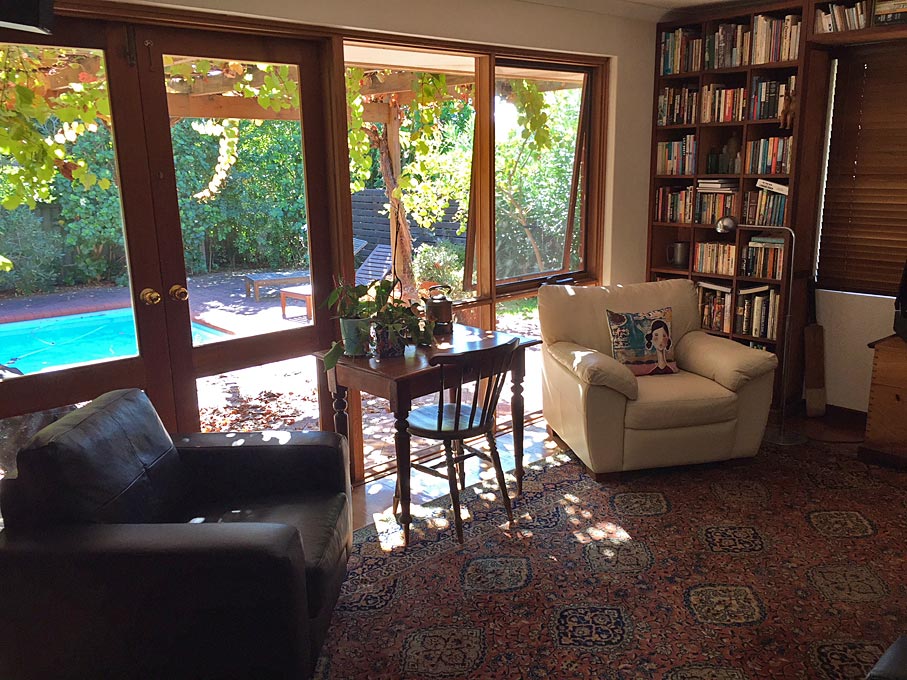
My wife requested a side table for the family room. This will be situated between two arm chairs, and replace the small table (which is too high and dominating) ...
Family-Room1.jpg


Not just a side table, but it also needed to house her needlework thingies. In other words, shallow drawers for cotton reels and sewing kit. I played around with several ideas, and eventually came up with a design that borrows a little from a piece I recently made for a nephew.

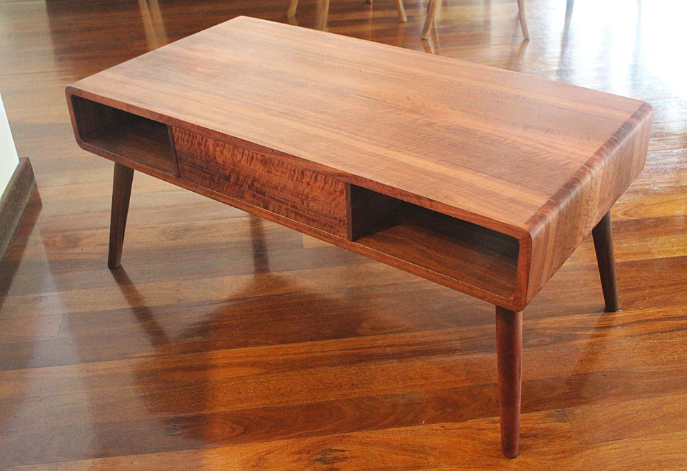
Lynndy liked the softness of the rounded dovetails and overall dimension of this coffee table I built some months back ...
12a.jpg


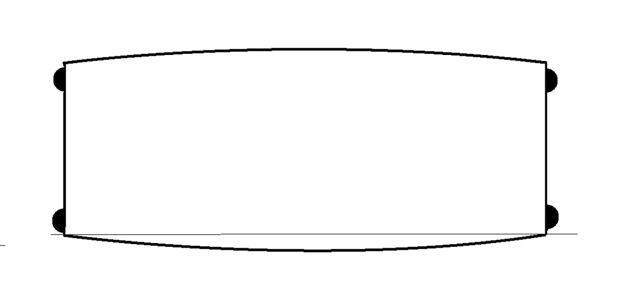
The plan (looking down) would be to create a curved front and back, with round, splayed legs to the outside (an alternative is a straight, tapered round leg) ...
B2.jpg


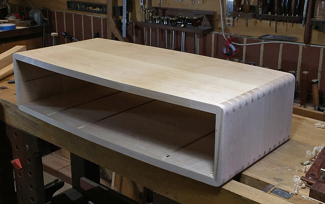
In contrast to the Jarrah in that piece, the carcase will be built in Hard Maple, dovetailed and mitred at each corner. It will feature 8 drawers. All drawer fronts will curve as well. The reason for "Harlequin" in the title is that the drawers will be a mix of woods, as depicted in the elevation of the drawer section ...

A.jpg


A harlequin design is often thought of as a diamond pattern, but does also include a rectangular checkerboard. Anyway, it's just a name, and I like giving my pieces a name :)

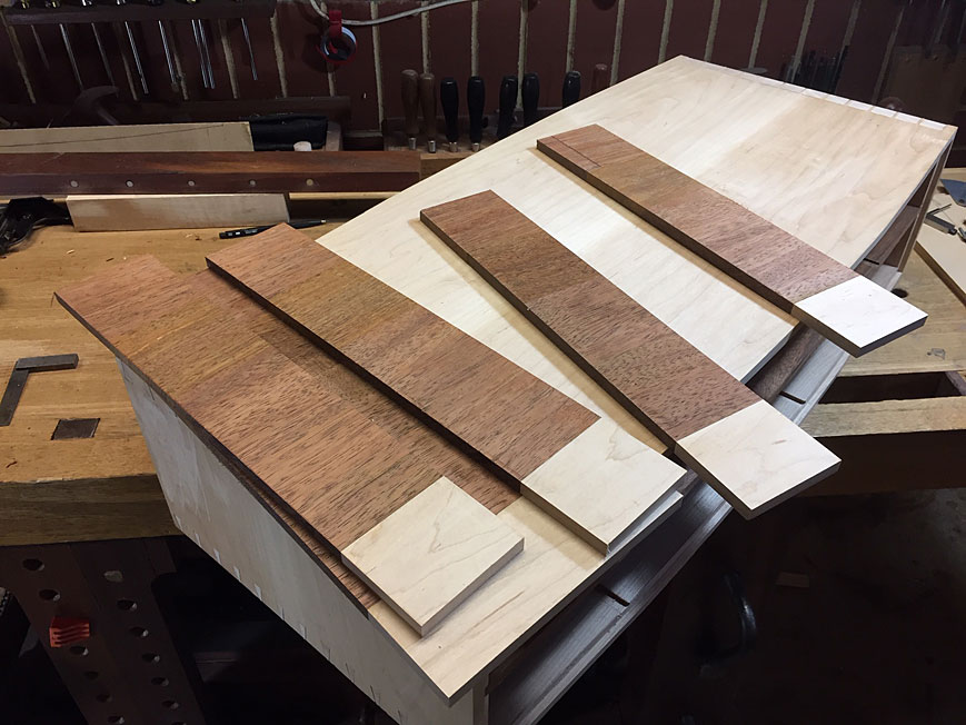
At this stage I have chosen for the drawer fronts Black Walnut and Blue Gum. I may also add in Hard Maple. Always interested in your thoughts here. The Blue Gum is lighter than the Black Walnut and is a good foil against the Hard Maple …
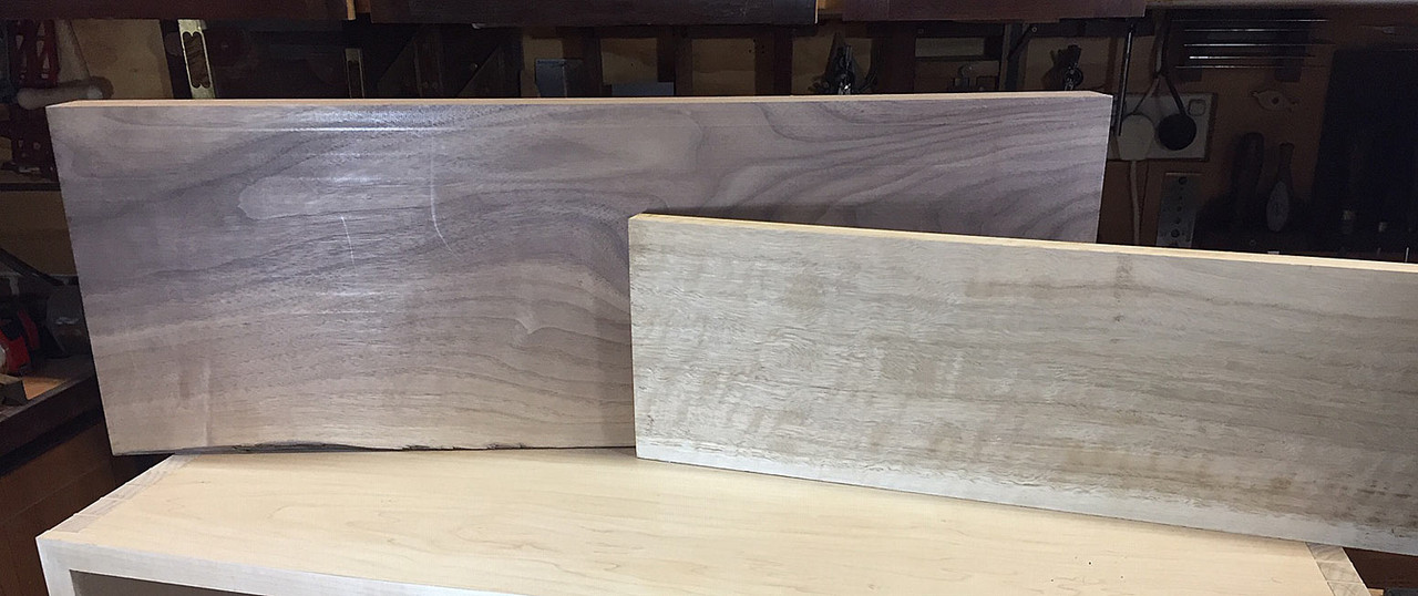
20.jpg


The legs will taper and curve from the carcase, attached with a loose mortice and tenon ...
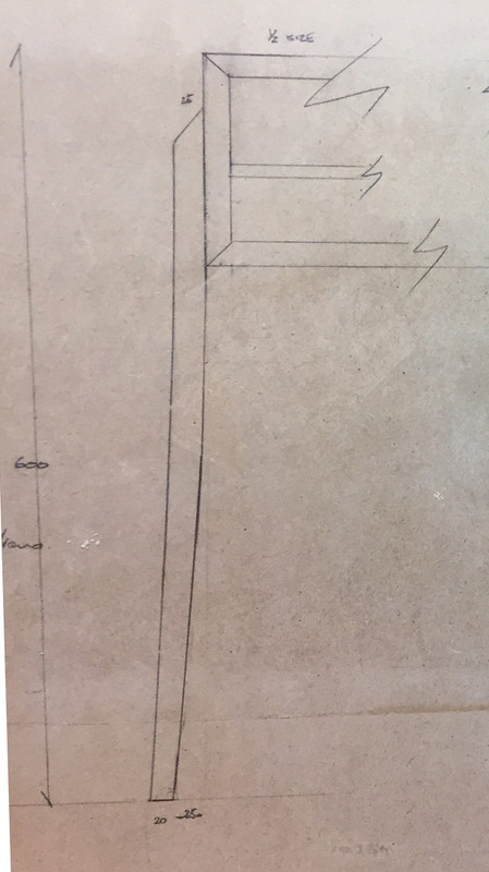
B.jpg


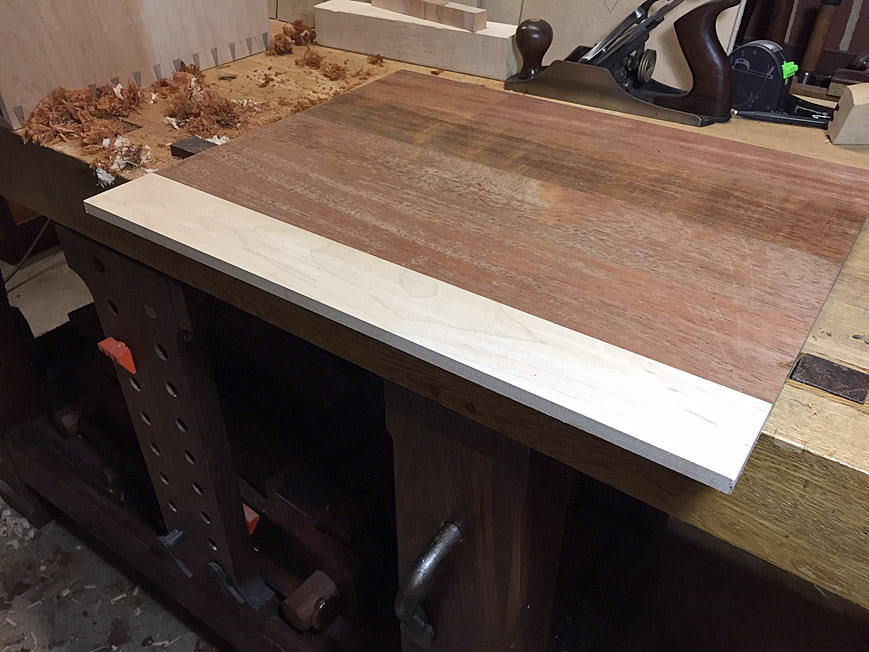
The sides and top were arranged so that the grain flowed continuously. The carcase is 20mm thick, 800mm long and 350 at the wide, centre point ..
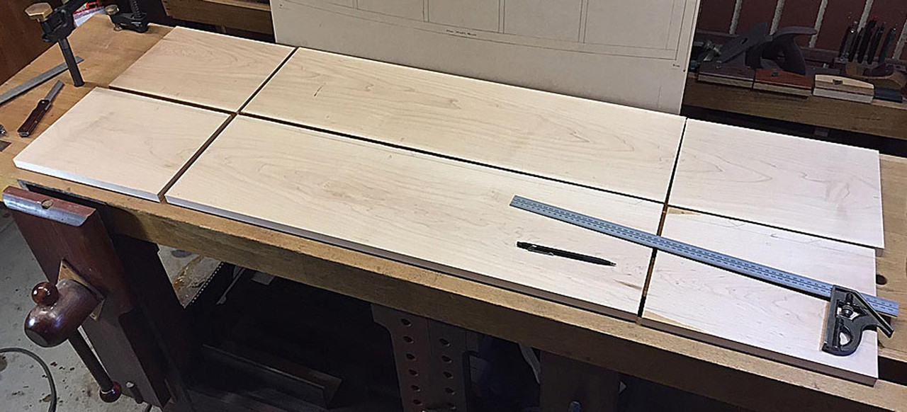
Arranging-boards3.jpg


The initial dovetail plan was to keep the boards parallel and saw the curves later. It became apparent when joining the first set that this would not work ...
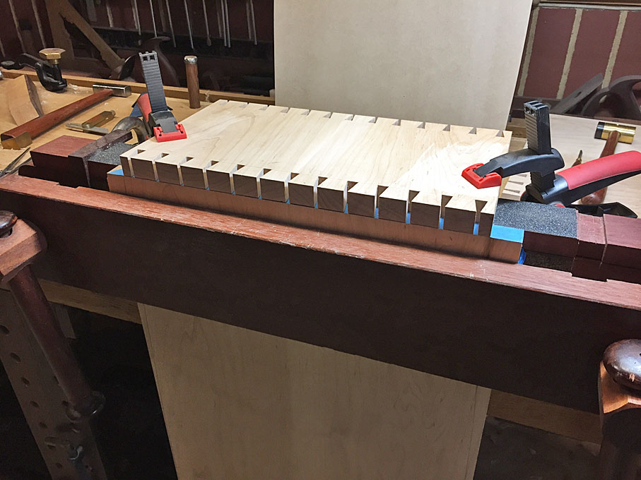
C.jpg


.. there would be too much at the sides to mitre, and so I decided to shape the top and bottom panels at this stage rather than later.
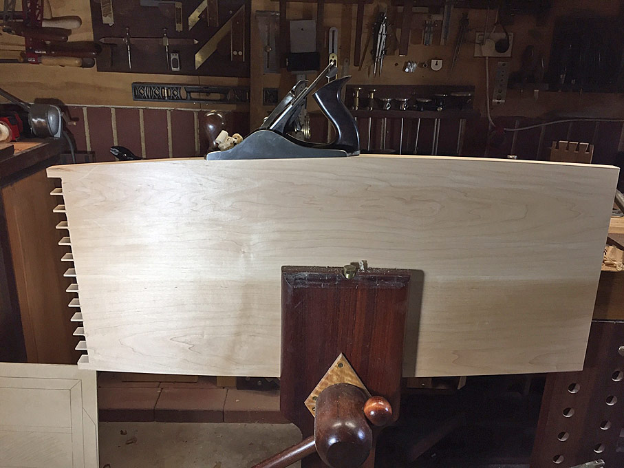
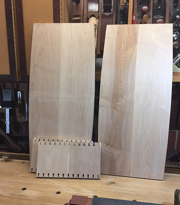
D.jpg


E.jpg


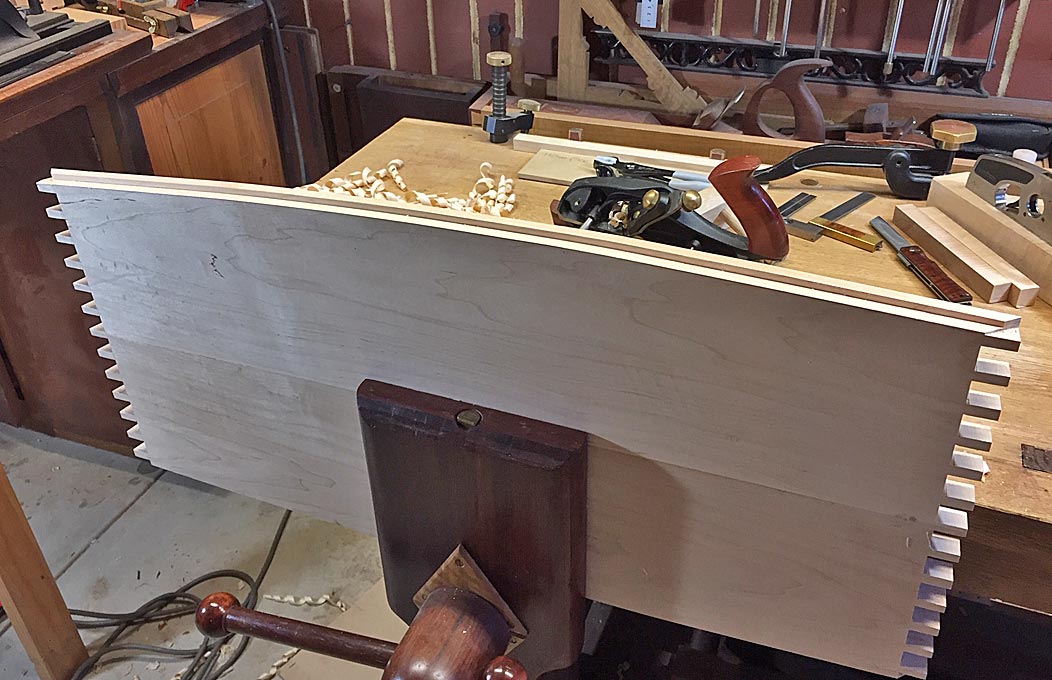
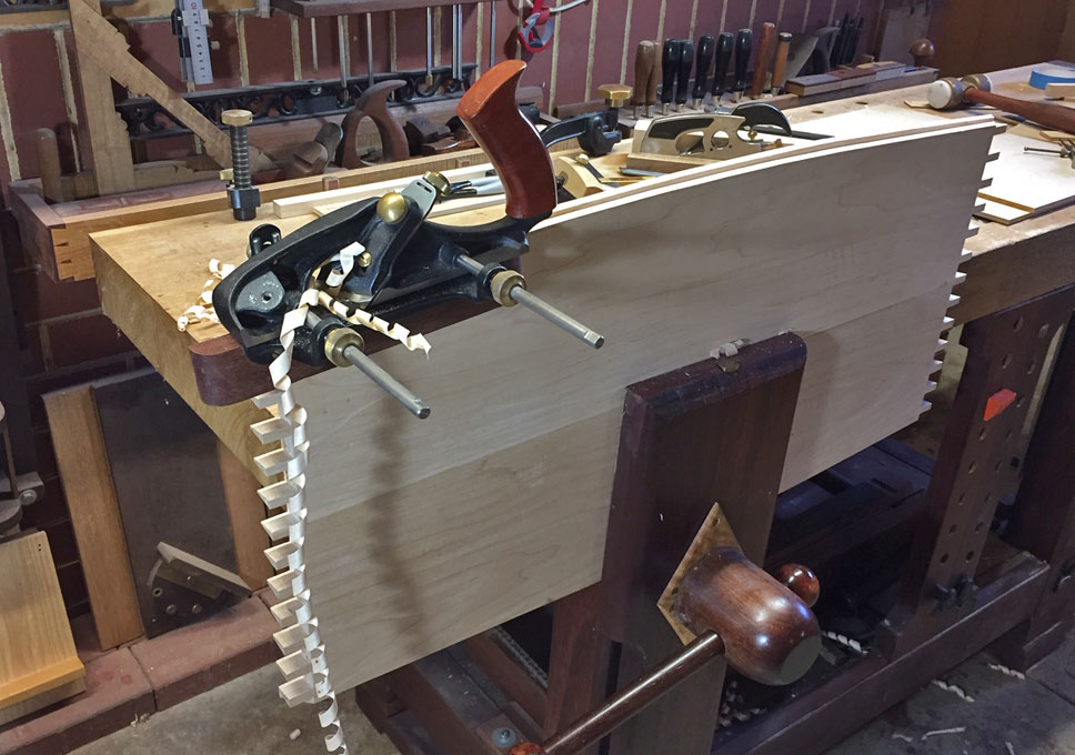
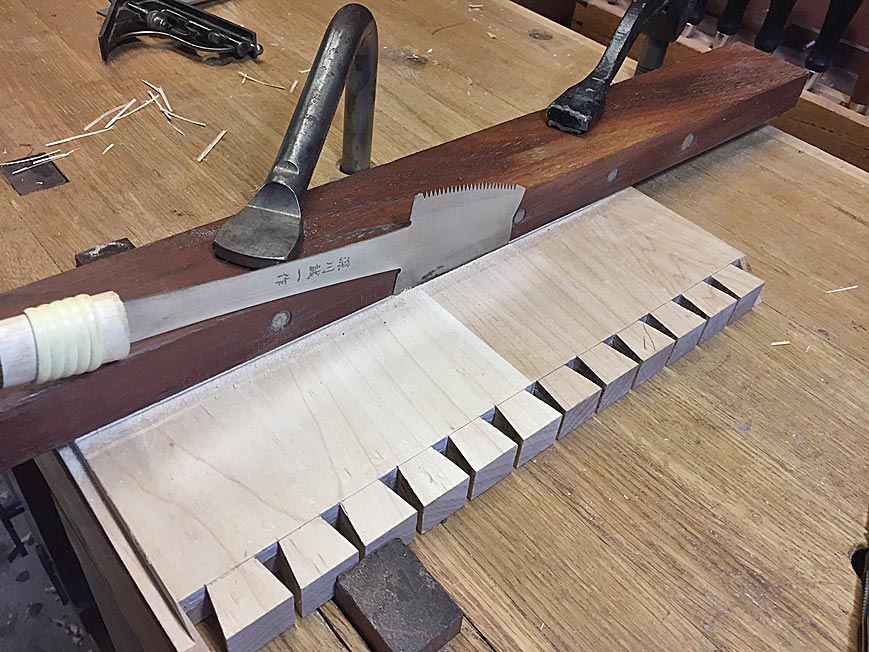
This was the first opportunity to use the modification I made to my Moxon vise (see article: http://www.inthewoodshop.com/ShopMadeTo ... nMods.html). It now enables the pin- and tail boards to be clamped together to aid in marking out (see earlier photo).

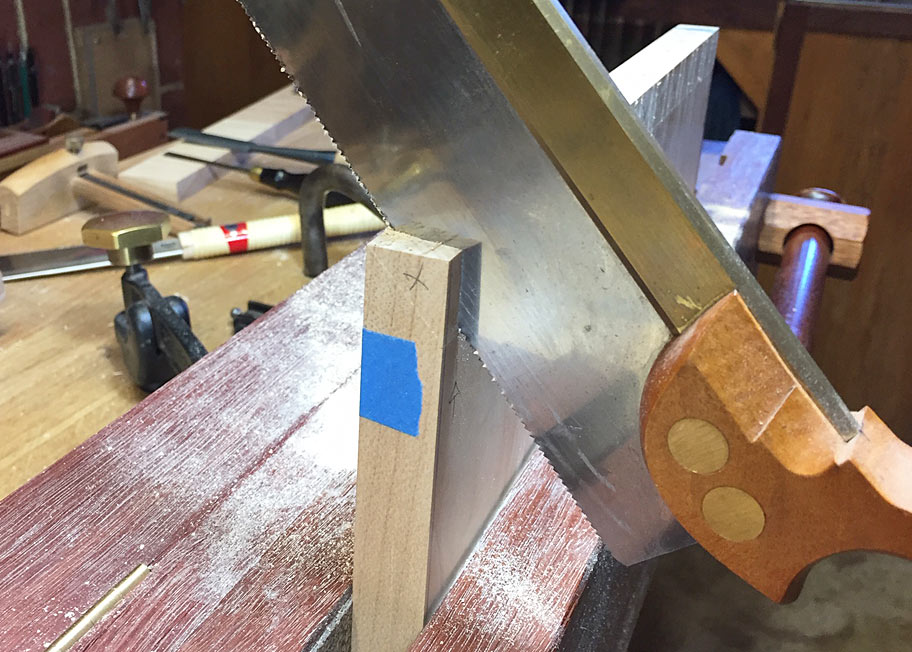
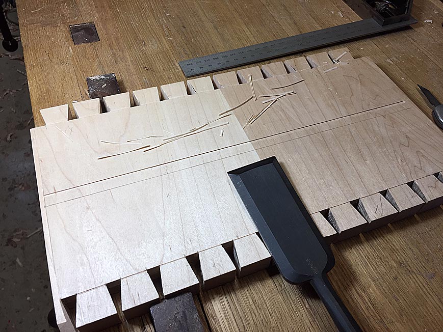
In marking out for mitred corners, the side tails are not sawn out from the front ...
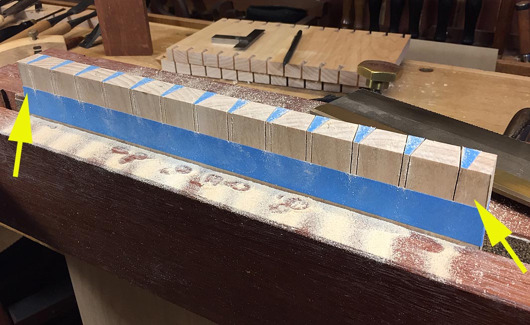
G.jpg


... the board is reversed, and the mitres are marked ...
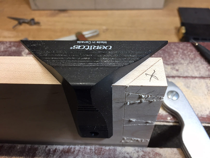
I.jpg


... and sawn ...

H.jpg


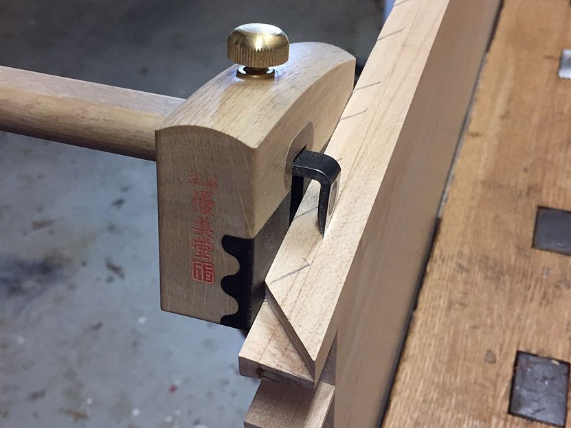
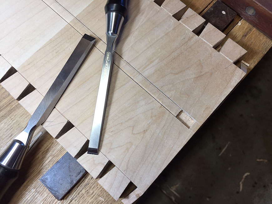
The reason I had wanted to retain square carcase sides was that it would make it easier to square the chisel guide for the mitres. I got around this by squaring them to the front of the carcase ...
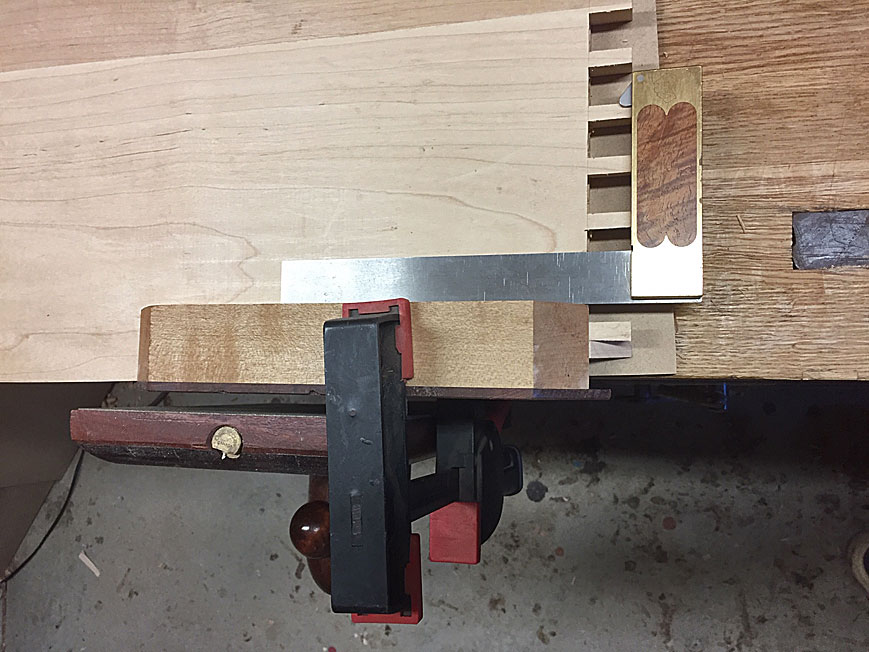
13.jpg


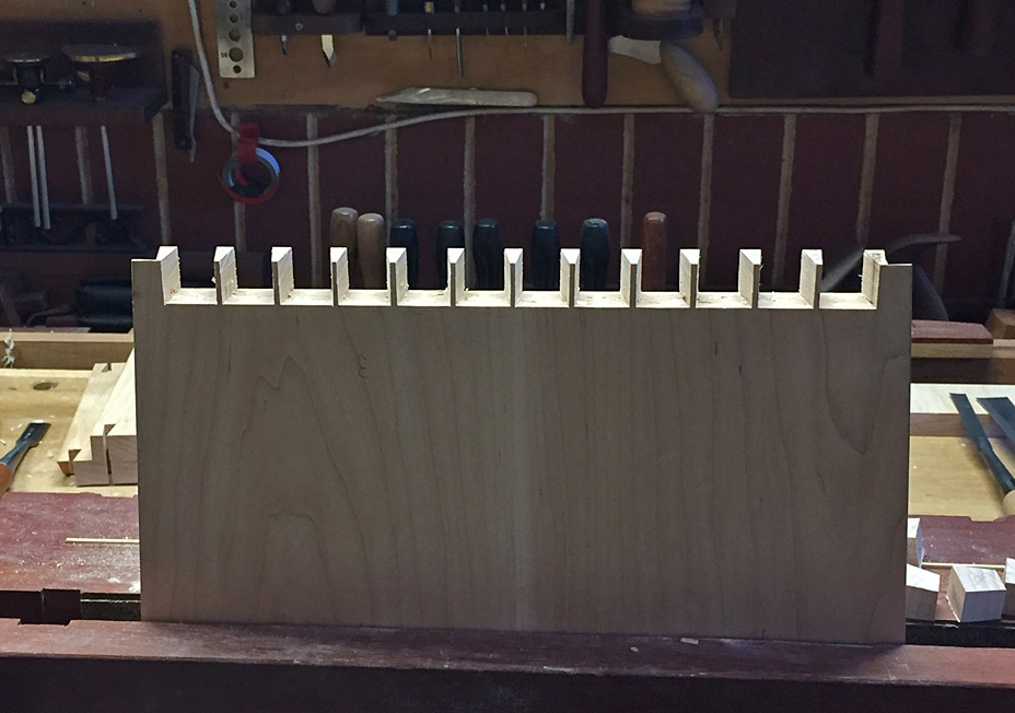
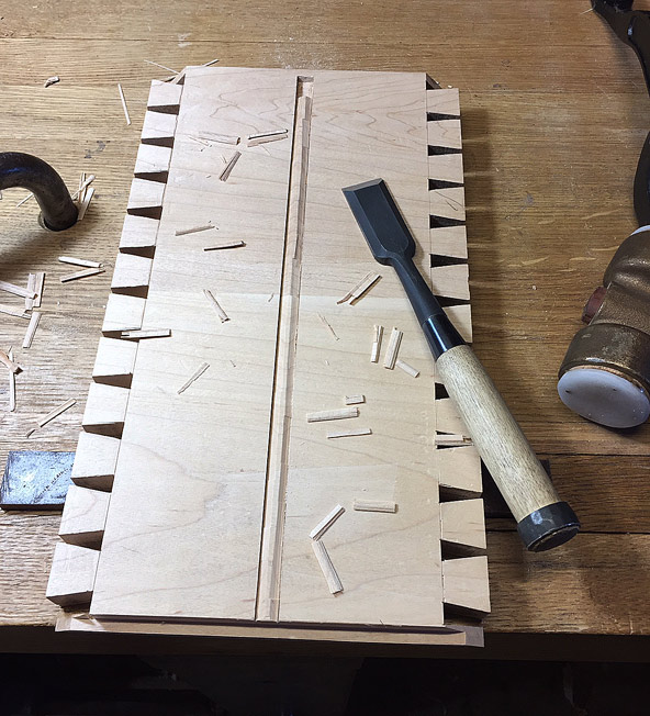
The pin board is seen here ...

J.jpg


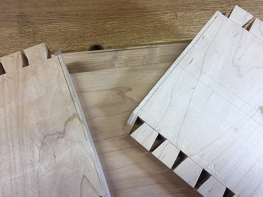
One of the difficulties in fitting this many tails and pins is that any slight errors are magnified. The fit below illustrates that the left side is too tight ...
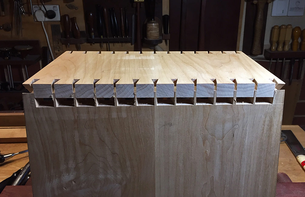
K.jpg


To deal with this, the tails were given a pencil scribbling ...
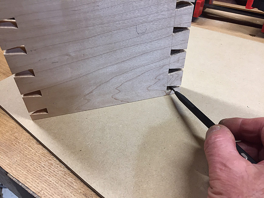
L.jpg


Fitting the board together left this behind ...
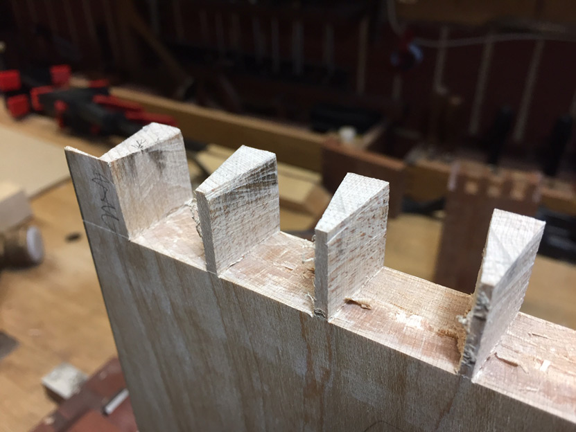
M.jpg


This process needed to be done once more, before the fit was satisfactory ...
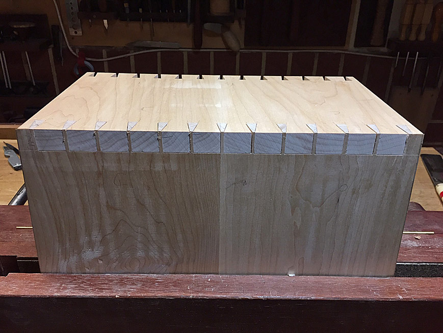
N.jpg


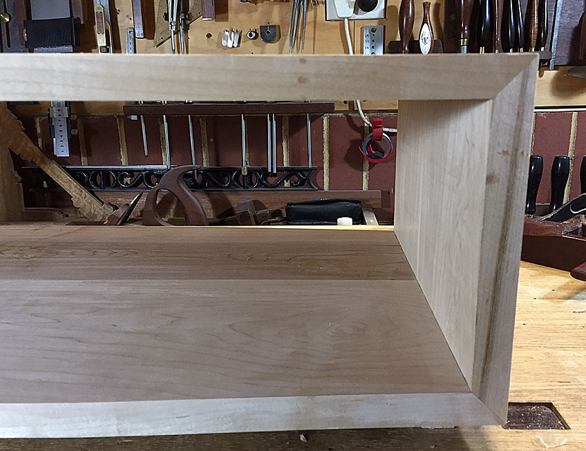
The four sides were dry fitted together, and the front and rear upper and lower panels planed to shape (this was close but not enough) …
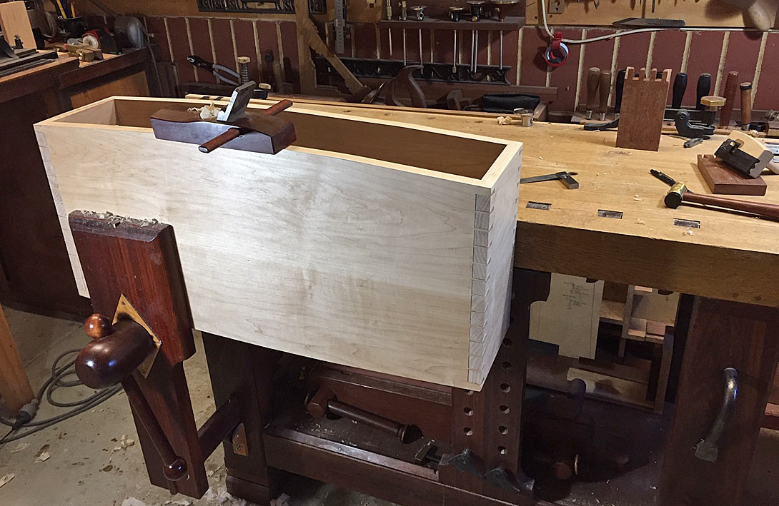
14.jpg


All is coplanar …

15.jpg


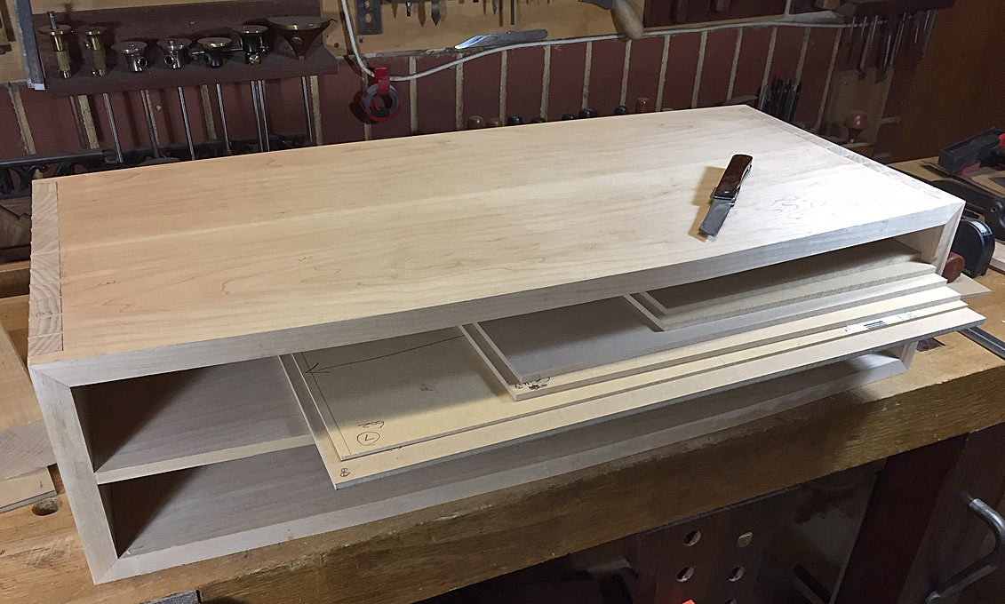
Where we are up to at the end of today …
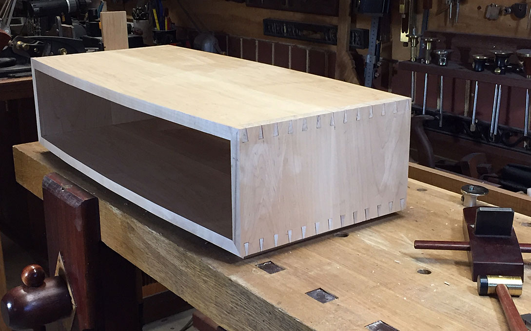
16.jpg


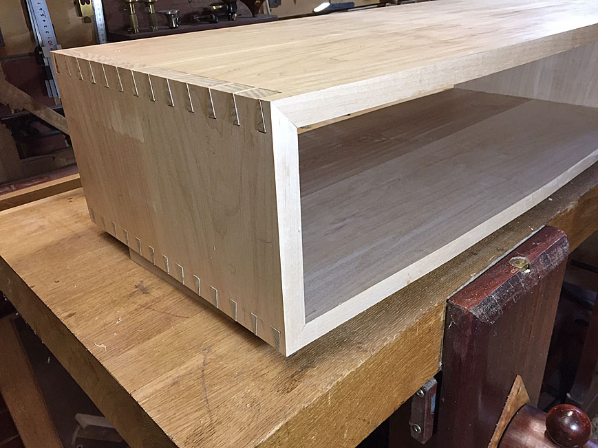
One set of mitred corners …

17.jpg


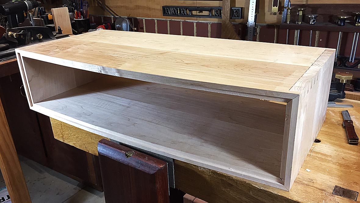
… and the other …

18.jpg


Next up is building the internal dividers for the drawers.

Regards from Perth

Derek
 
Blimey Derek, I've seen your stuff on here before, but your current post just reminds me that I shouldn't post my stuff here too - we're not even on the same planet (never mind continent)!

Lovely stuff - that I don't think I can ever aspire to.
 
Bloody Norah your stuff is an inspiration, to make something of that quality, and progress so far in a day is a far off dream for me! Thanks so much for your build posts they are great!

Fitz.
 
Never in a day!

One weekend was just preparing the boards and templates. Another weekend and a half went in dovetailing the sides. Today I need to prepare the boards for the internal dividers, their templates, and see how far I can get with housing joinery.

Regards from Perth

Derek
 
With the carcase completed, it is time to turn to the internal dividers for the drawers.

I took the time first to plane the rebate for the rear panel. Knowing my spatial weakness of getting parts back-to-front and upside-down, I marked these when the carcase was a dry fit (and later briefly thought I had screwed this up!) ...

Mon1a.jpg


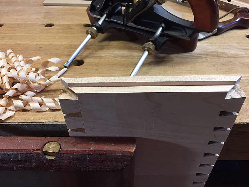
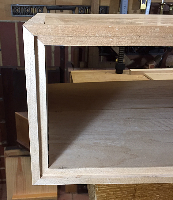
One of the benefits of mitred corners is that the rebate can be planed across without fear of it showing ...

Mon2a.jpg


Mon5a.jpg


The rebate is 6mm deep as the rear panel will be 5mm thick to bend it around the curved rear. The carcase is 20mm thick, and the rebate extends halfway into this.

I was curious to see how rebating on a curve would turn out. No problem ...

Mon6a.jpg


Mon7a.jpg


Here is the rear of the carcase with the rebate ...

Mon8a.jpg


Mon9a.jpg


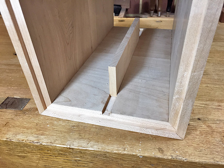
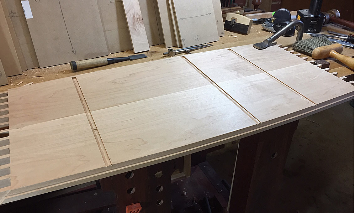
Moving to the stopped dados/housings ... the centre panel is solid rather than a frame. I decided that this would be less work, plus there will be a series of stopped dados to be made. The panel is 10mm thick. This was made first, that is, the dados were sized to fit the panel thickness.

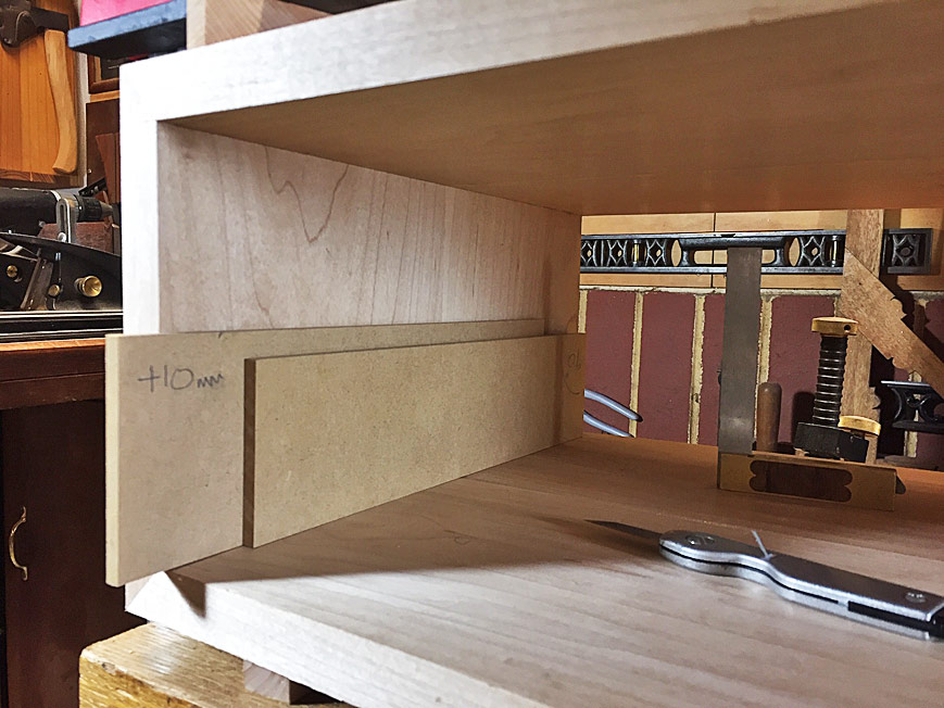
I made up a couple of templates. One was the height of the dado, and the other was the height of the dado plus the width of the dado. The inside of the carcase is marked on both sides using the same templates to ensure that they are exactly the same height from the base.

Mon10a.jpg


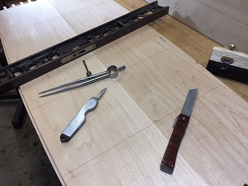
The lines are deepened with a knife, and then a chisel wall is created to register a saw cut ...

Mon11a.jpg


The end of the stopped dado is defined ...

Mon12a.jpg


A Japanese azebiki was used along a guide to ensure it cut on the vertical ...

Mon13a.jpg


Now that the sides are defined by the kerf, this could be deepened with a chisel (this is my favourite chisel - a 1" Kiyohisa. Sublime!) ..

Mon14a.jpg


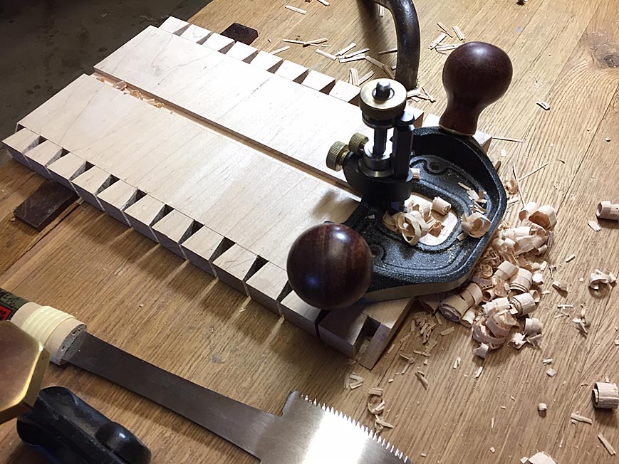
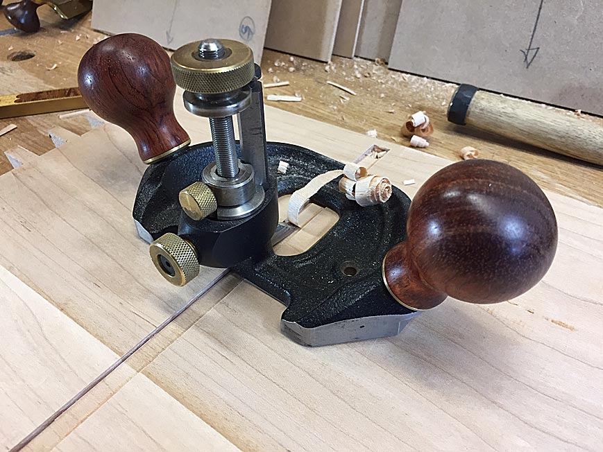
The waste is removed with a router plane ...

Mon15a.jpg


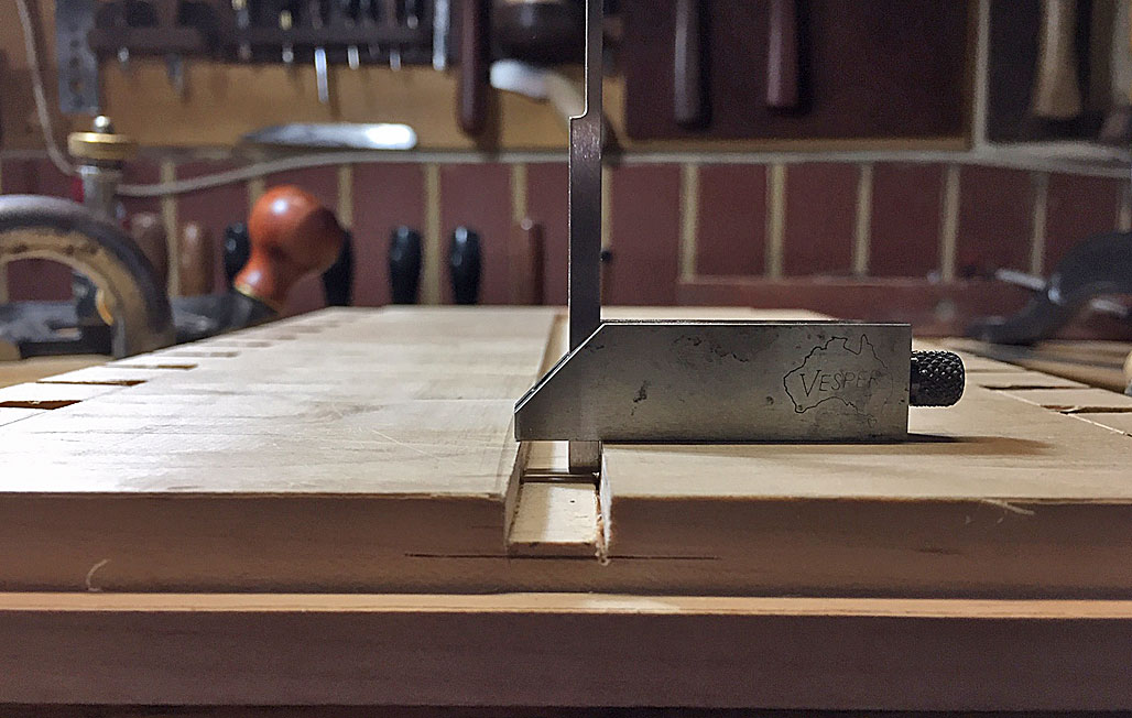
Check that the side walls are square ...

Mon16a.jpg


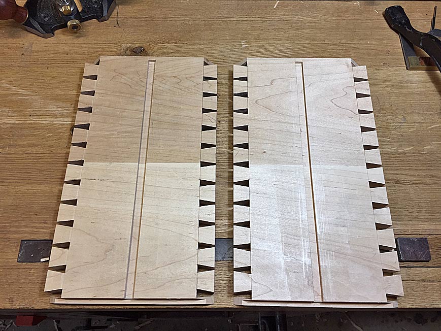
Completed side panels ...

Mon17a.jpg


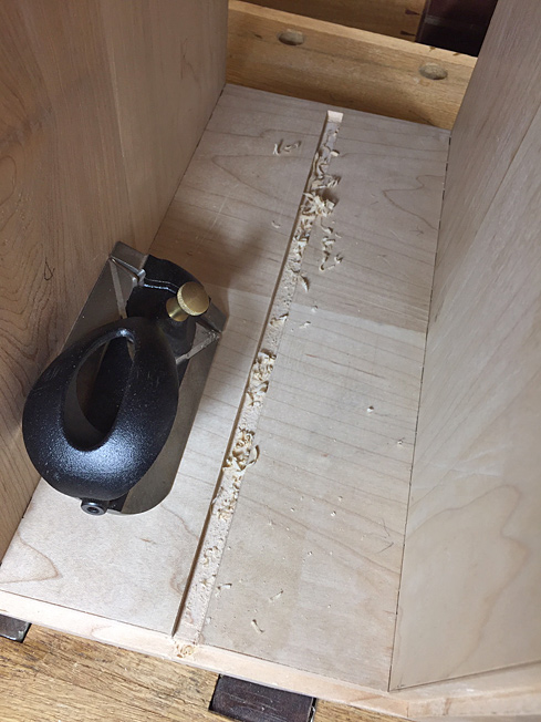
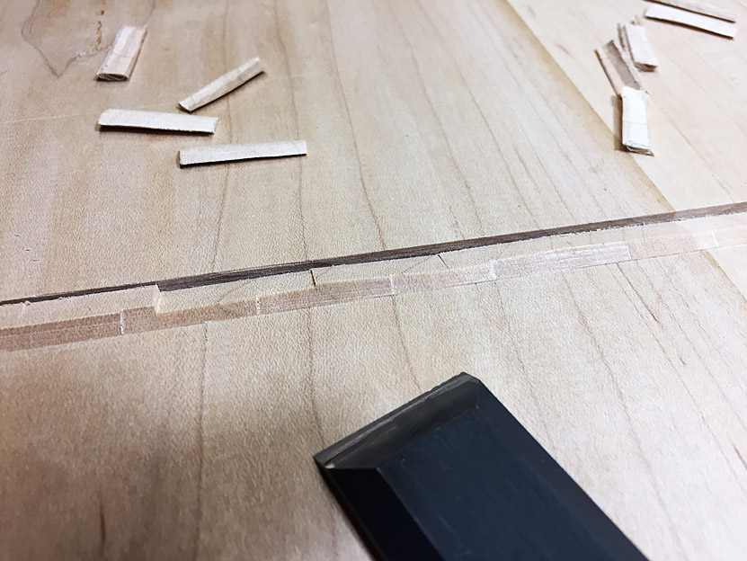
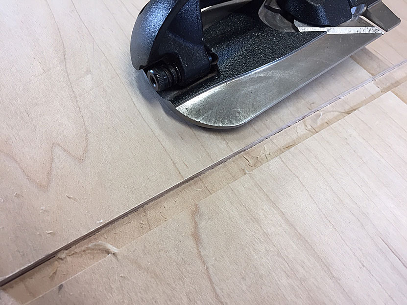
I was so confident that the dados were perfect that I dry fitted the carcase once more ... and then found that one dado was a smidgeon too tight for the test piece. It turned out that a small section of a side wall was not as square as I thought (probably the saw did not cut deeply enough at that spot). The best too to clear this is a side rebate plane. Set for a very light cut to clear the waste, not the dado width ...

Mon18a.jpg


Perfect fit this time ...

Mon19a.jpg


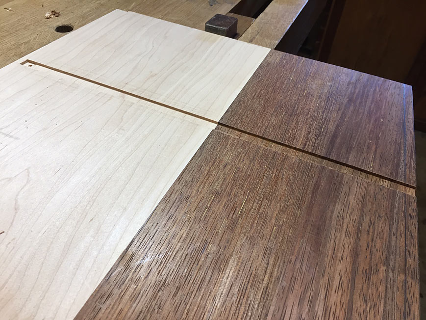
Time to fit the centre panel. This has been shaped to size, but will need a little fine tuning at a later time. Note that the rear section is secondary wood (Merbau) ...

Mon20a.jpg


I had just enough time to slide the panel in. Nice tight fit. Not enough time to saw the rebates for the stopped dados. This will be done next time ...

Mon21a.jpg


Regards from Perth

Derek
 
I really like your quality of work and the write up and photographs.
I must disagree with the comment from AES. I really like seeing all the projects whether on here or the projects section whatever the standard and wish more people would post their work. I have never seen a negative comment and often there are very positive ones and advice for improvements.
Ian
 
Sorry if there was any offence to anyone Hornbeam, definitely NOT intended. But when I compare the sheer quality of the above work to my own attempts at "simply joining bits of wood" (ply in my case!) there is simply no comparison. Literally different (woody) worlds. That's all I meant.

OTOH, there are some quite IMO "clever" little metal bodges & fixes in my MG pedal car (Project Section, Part 4 coming soon). But as I say, proper "cabinet work it ain't!
 
Hi AES. There was no offence. I just wish more people would post images and details of their projects. Always good for ideas and inspiration what ever the level
Ian
 
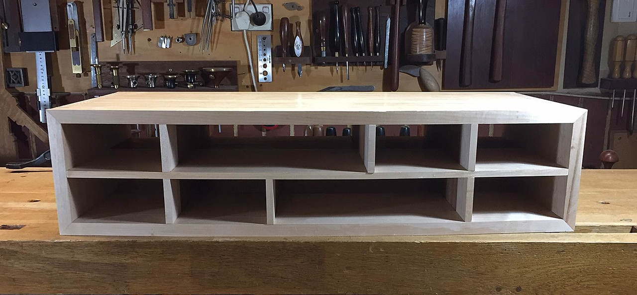
The Harlequin side table will have 8 drawers. The drawer case sides and the central drawer blade are panels and run in dados or housings (depending on which side of the pond you live). Positioning of these dados is critical since any misalignment will affect the aesthetic. It goes without saying (but I shall) that the alignment also determines that the side panels will be square ... and drawers need to run against square sides. All this is done here with hand tools.

Some of the finer points in getting it precise ...

First of all, templates (or story sticks) are created to position the dados. There are two for each side panel: the second is 10mm longer than the first. Scoring each creates an exact 10mm dado. There is a series of templates to position all the dados. This ensures that the upper and the lower dado are position exactly the same distance from the reference wall ...

25-2(3).jpg


25-3(3).jpg


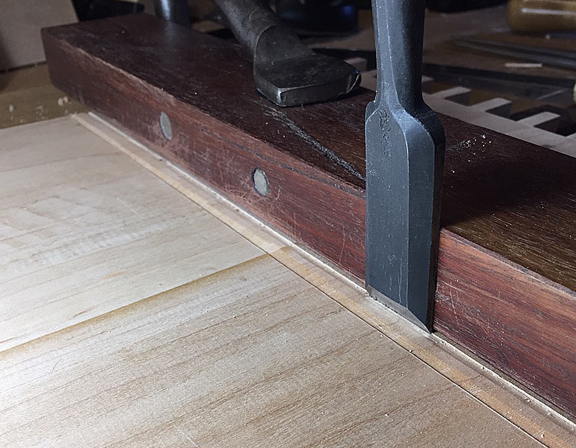
A chisel wall is created for the marked outlines. This wall enables the fence to be lined up using a wide chisel ...

25-1(3).jpg


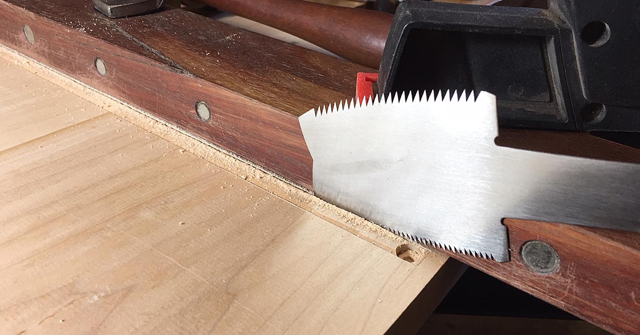
The sidewalls are sawn with a azebiki saw. This have two curved sides, one with coarse rip teeth and the other with fine crosscut teeth. I begin with the fine teeth and use them to establish the kerf, and then switch to to the coarse teeth for speedier sawing.

26.jpg


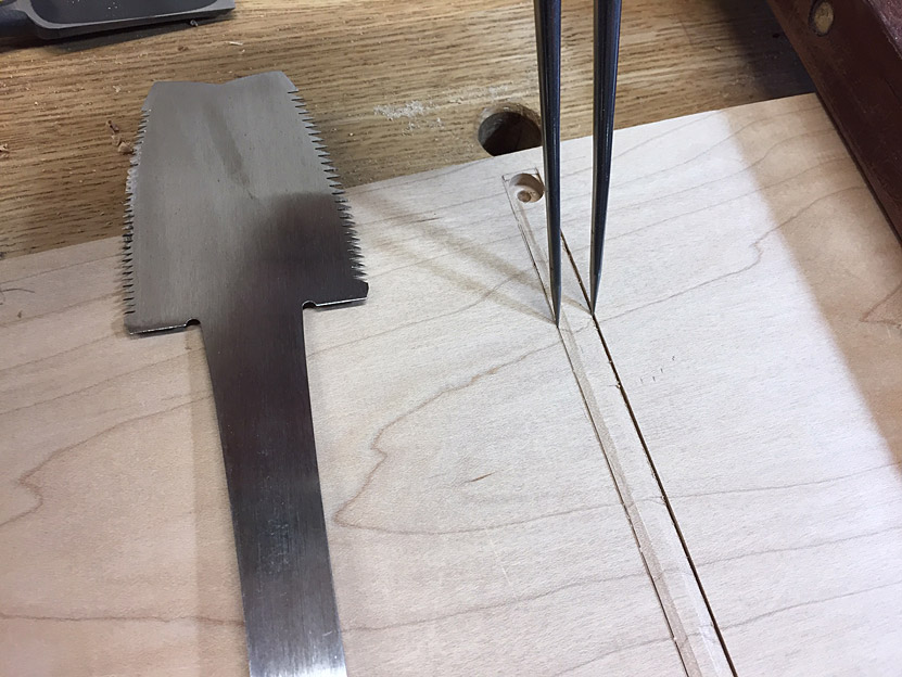
With a compass, I check that the kerf is parallel and to the desired width (10mm) ...

27.jpg


The sawn side wall is now chopped away close to full depth ...

28.jpg


This is done across the dados on one board at a time ...

29.jpg


The waste in the centre of each dado is removed with a router plane. The dados are done at the same time to save have to reset the depth of cut (one stroke on dado #1, one on dado #2, and one on dado #3 ... then back to #1 ...) ...

30.jpg


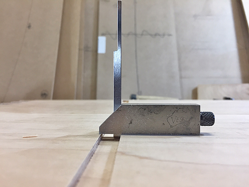
Keep an eye on the depth ...

31.jpg


Fine tune the dado should theoretically be unnecessary if they were marked accurately. In practice, I find that there is usually some waste in the corners, or a slightly sloped wall. For this reason I run a side rebate plane (here a Veritas), the length of each wall. This is not held vertically, since that with remove some of the width. Instead it is run at an angle away from the side wall, as it it was undercutting the side wall ...

32.jpg


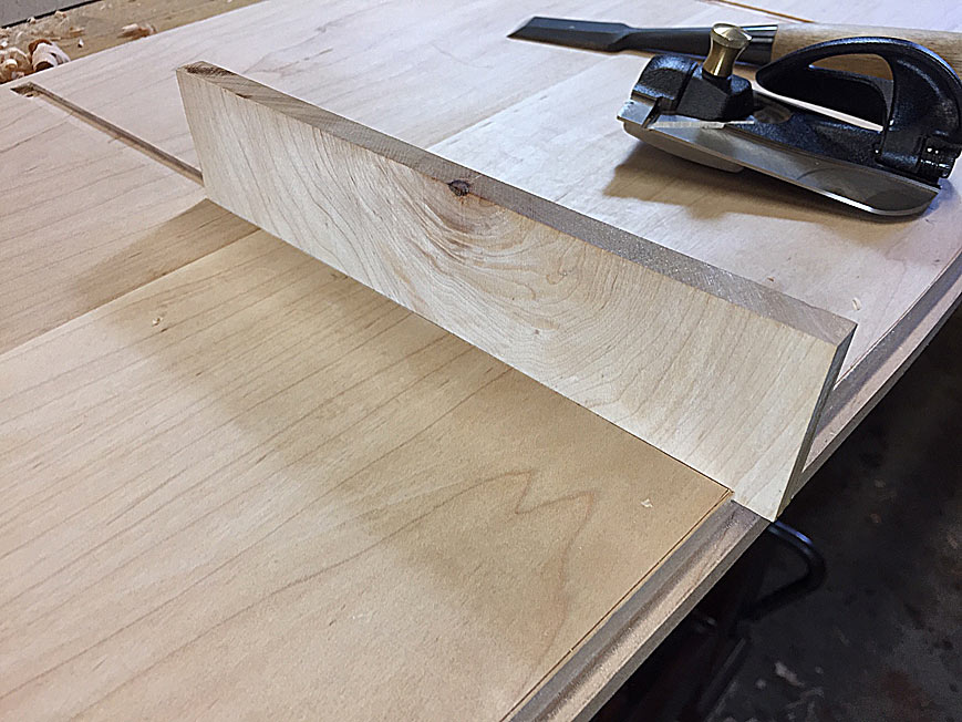
The fit is now checked with an offcut from the side panel ...

33.jpg


The side rebate plane can take a smidgeon off the sidewall if the fit is too tight. Some will argue that it is preferable to plane the panel instead. In this situation that is not advisable since the panel is to slide along the dado, and a tight point will impede all points of the panel.

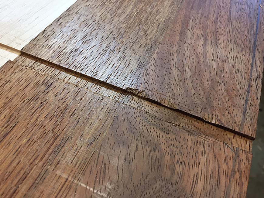
The carcase is Hard Maple, with Merbau as the secondary wood. Locally, Merbau is used for decking. It is cheap and hard, both qualities valued. But is a really brittle wood, and awful to work with. The number of splinters I have had ... and they are sharp and lodge deeply. Ugh!

It can look like this ...

34.jpg


... and then a section breaks away ...

35.jpg


At least it will be far inside the carcase and not be seen.

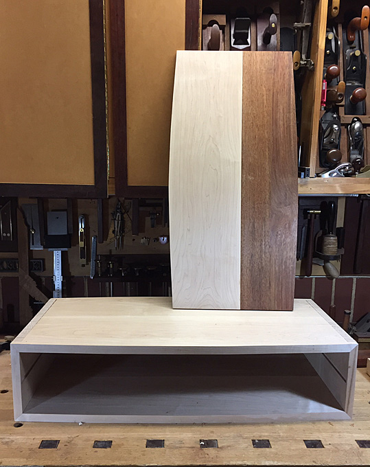
A panel is made up for the interior dividers ...

36.jpg


37.jpg


The pieces are fitted.

Will the careful planning and neurotic execution pay off?

I was holding my breath. This is a dry fit ....

38.jpg


39.jpg


40.jpg


(sound of breathing again)

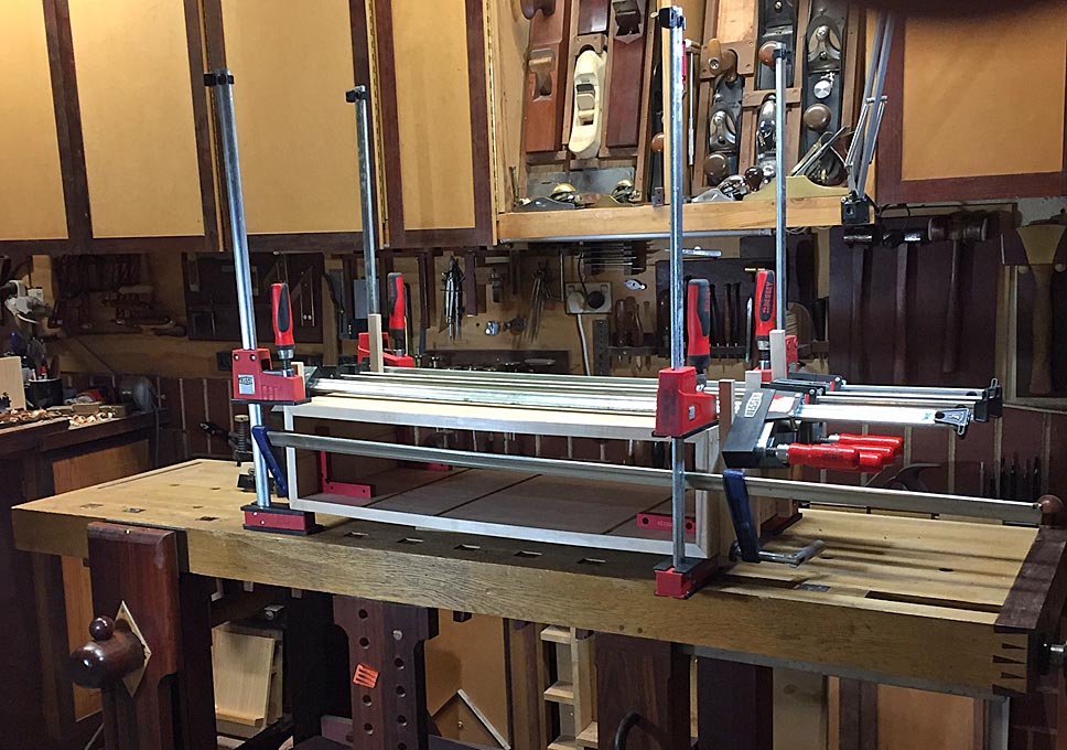
Then I pulled it apart and glued up the carcase ...

41.jpg


More after the coming weekend.

Regards from Perth

Derek
 
YOUR INPUT PLEASE

The Harlequin side table will have round legs at each corner, which will be attached from the outside.

B2.jpg


B.jpg


Ideally, the legs will be attached without any bracing. I would prefer to not even have a stretcher between the legs, however recognise that my intended connection of the legs to the case may not be enough to prevent flex in the legs.

The plan I have is the attach a wedged through loose tenon into the case (which is 20mm thick), and connect the legs to this with a pinned mortice-and-tenon.

This will need to be done before starting on the drawers (for access). The wedging should prevent the tenon from being pulled out, and the pinning with prevent the tenon separating from the legs.

The legs are likely to be 1-3/4” to 2” diameter (not exactly sure yet) at the top, so can be morticed 1-1/4” deep. If the tenon is 75mm long, will this be wide enough to prevent any twisting? Or do I still require a stretcher?

Any other ideas to attach legs? (No, I am not considering a frame below the case).

Regards from Perth

Derek
 
Derek, we all know that you can cut amazing, precise joints, so I'd like to just plant the seed of a different approach altogether. Maybe so basic and simple that you rejected it without even considering it...


Screws.


Two or three per leg, from the inside. Accessible by using the right sort of driver/adaptor/ratchet and screws with well chosen heads (torx or similar).

Advantages - you can pull them up tight and retighten if necessary. Minimum material cut away from the box. And if one or more of the (unbraced) legs twists out of shape after a few years in the house, you could replace them easily.

There's plenty of precedent for using screws in quite high end furniture. They're not just for flat pack!
 
At the start of the thread I mentioned that the case will have rounded dovetails, which means that there will not be an edge or ledge to use to support the legs.

Screws are out. The issue is that the case is 20mm (possibly 19mm). The head of the screw must sit flush with the inside (as the drawer runs along the inside), which means that it must be countersunk. This means that the thickness surrounding the screw is potentially thin. Movement will eventually cause this to crack or break away.

The only solution I can see is a morticed loose tenon. 12.7mm (1/2") wide x 75mm long and 20mm deep. The question is whether this needs to be wedged or not. There are pros and cons each way. The pro is the obvious one - a wedged tenon acts like a dovetail and will resist being pulled out. The con is whether the wedge will weaken the tenon, since it can only be 20mm in depth (angled saw kerfs terminating in a drill hole to prevent splitting). And at its simplest, the tenon may be strong enough with glue alone. Any particular glue (I have been using Titebond Liquid Hide)?

It could come down to glue area. Is 20mm deep x 12.7mm wide x 75mm long (proposed here) the same as 35mm deep x 6mm wide x 75mm long (as in the last sofa table I built)?

Regards from Perth

Derek
 
You could let in a strip of 3mm brass with countersunk holes in it to spread the load.
 
We left off with the drawer dividers a dry fit in the case ...

38.jpg


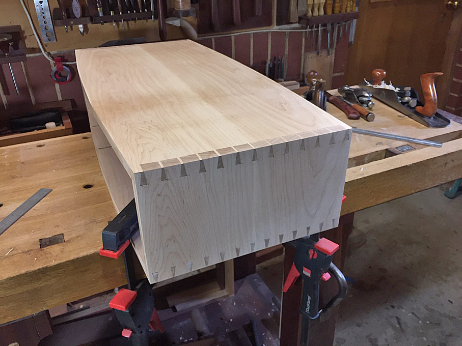
And then this was pulled apart and the case glued up. After a clean up, the ends were looking a little tidier ...

42.jpg


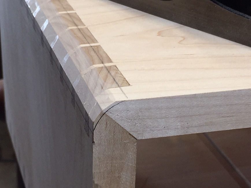
Now we've been through this together with the Jarrah coffee table, but for those who want to know how ...

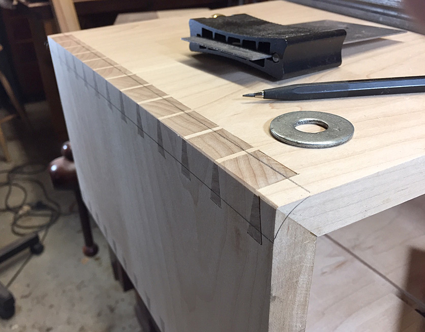
The ends are marked (with a washer) ..

43.jpg


The aim is the remove the waste progressively to the lines ...

44.jpg


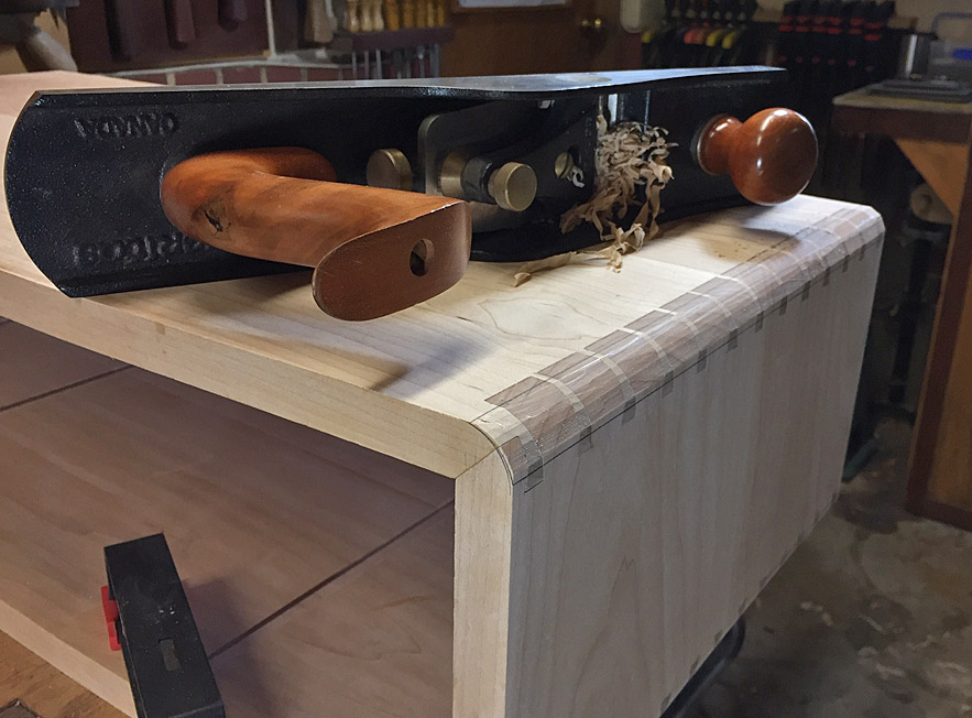
This is quick to do with a low angle jack ...

45.jpg


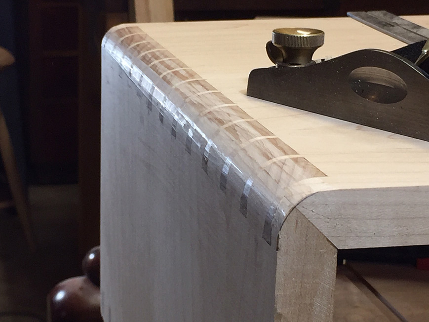
.. and finish with a block plane ...

46.jpg


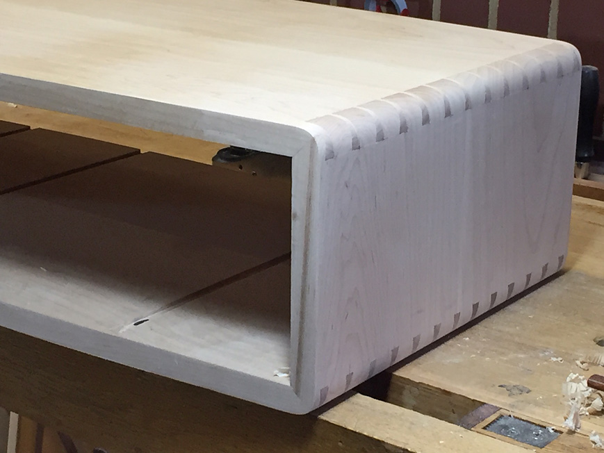
Now finish with sandpaper - 80/120/240 grit ...

47.jpg


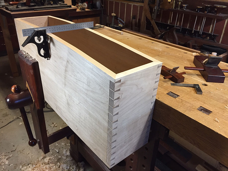
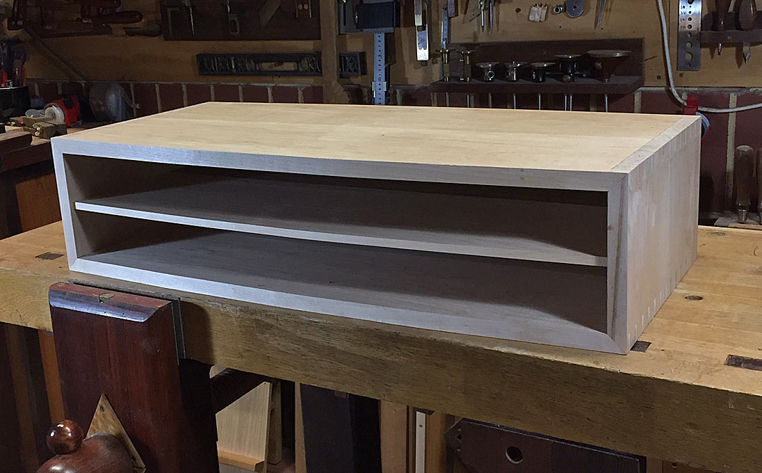
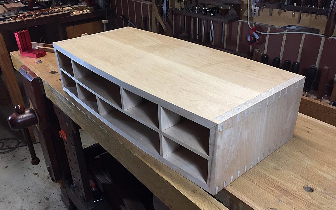
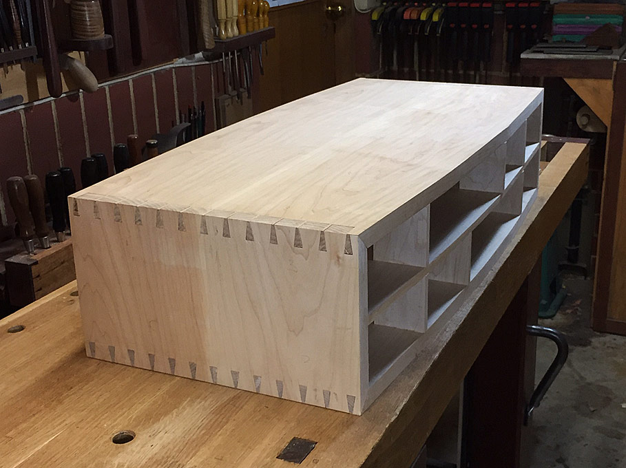
The completed case ...

48.jpg


I spent a few hours today turning a few legs. Rather than show the prototypes, I am hoping that I may have enough time to complete them tomorrow - I have the afternoon off! :) - and then I will post more photos.

Regards from Perth

Derek
 
Impeccable workmanship as always Derek. For a self taught, weekend cabinet maker you really are operating at a seriously high level!

=D>
 
Agree with Custard. Theres a lot of excellent work there, and a great WIP. Thanks for taking the time to document the process.
 
This is quick to do with a low angle jack ...
.. and finish with a block plane ...
Now finish with sandpaper - 80/120/240 grit ...
I am perhaps a heathen for suggesting it, but my process for rounding a corner like that would have involved a fine file between planes and sandpaper. I find I can work more slowly and accurately with a file than I typically do with sandpaper. Would that pose any problems I am overlooking?
 
I am perhaps a heathen for suggesting it, but my process for rounding a corner like that would have involved a fine file between planes and sandpaper. I find I can work more slowly and accurately with a file than I typically do with sandpaper. Would that pose any problems I am overlooking?

The sandpaper is just to fair and smooth off the curve. The shaping has been done with the planes.

I try and maintain reference lines/sides throughout. Planing across the grain (one edge to the centre only) allows me to track and see the lines. Everything remains square and coplanar. If one tried to rasp the curve, you will find yourself losing the reference.

How would you do this, Custard?

Regards from Perth

Derek
 

Latest posts

Back
Top