Dining Table

UKworkshop.co.uk

Help Support UKworkshop.co.uk:

This site may earn a commission from merchant affiliate links, including eBay, Amazon, and others.

Derek Cohen (Perth Oz)

Established Member
Joined
2 Mar 2005
Messages
3,354
Reaction score
1,832
Location
Perth, Australia
Part 1 - design and construction

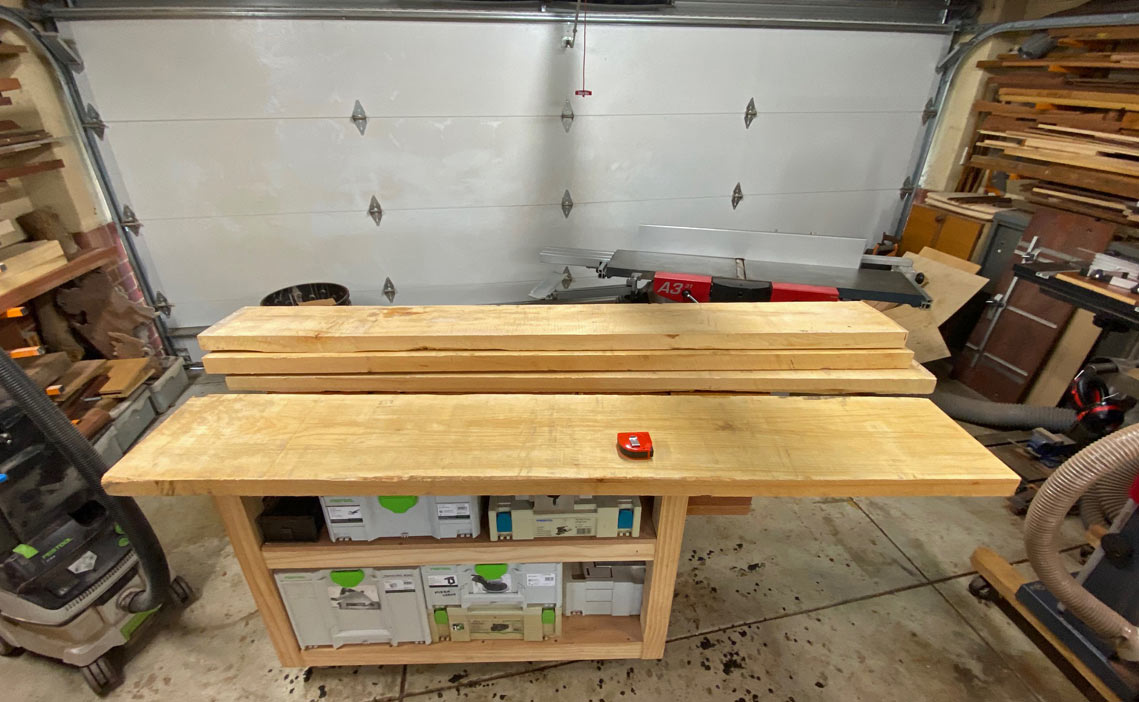
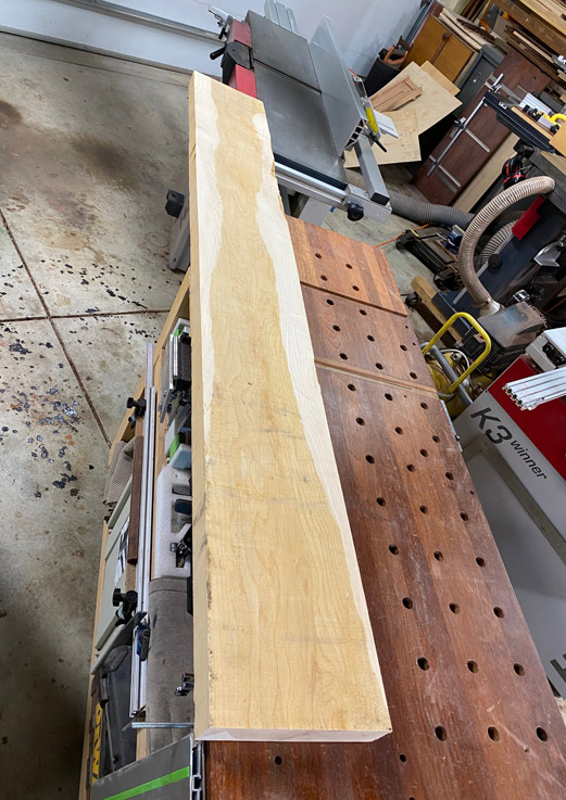
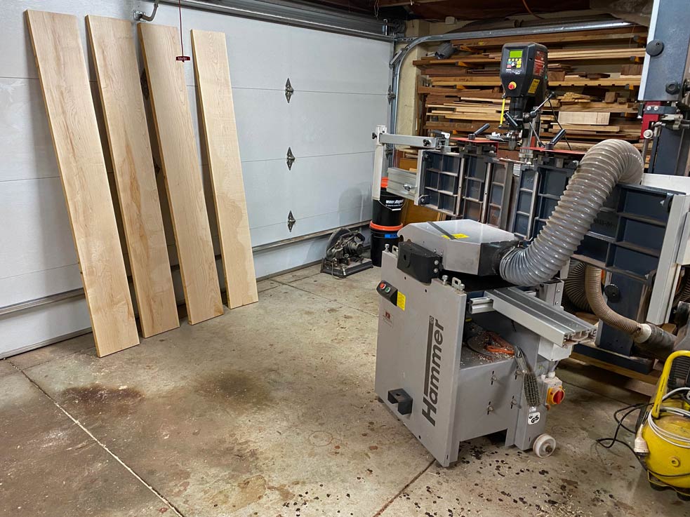
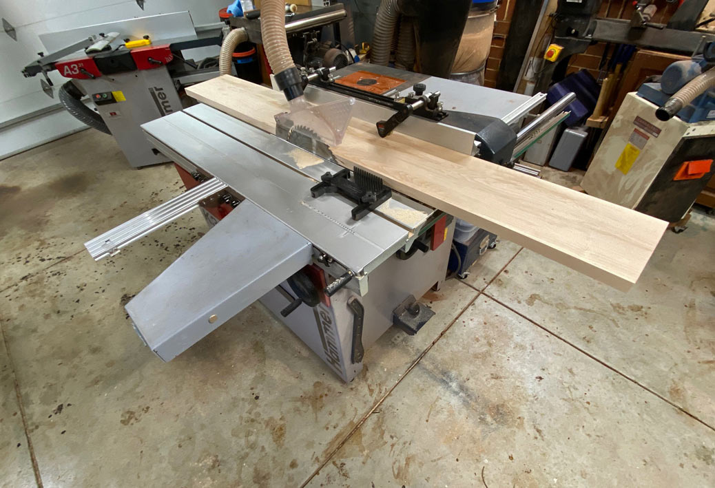
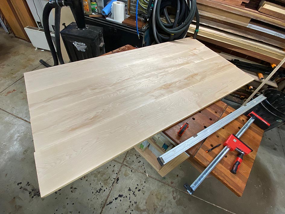
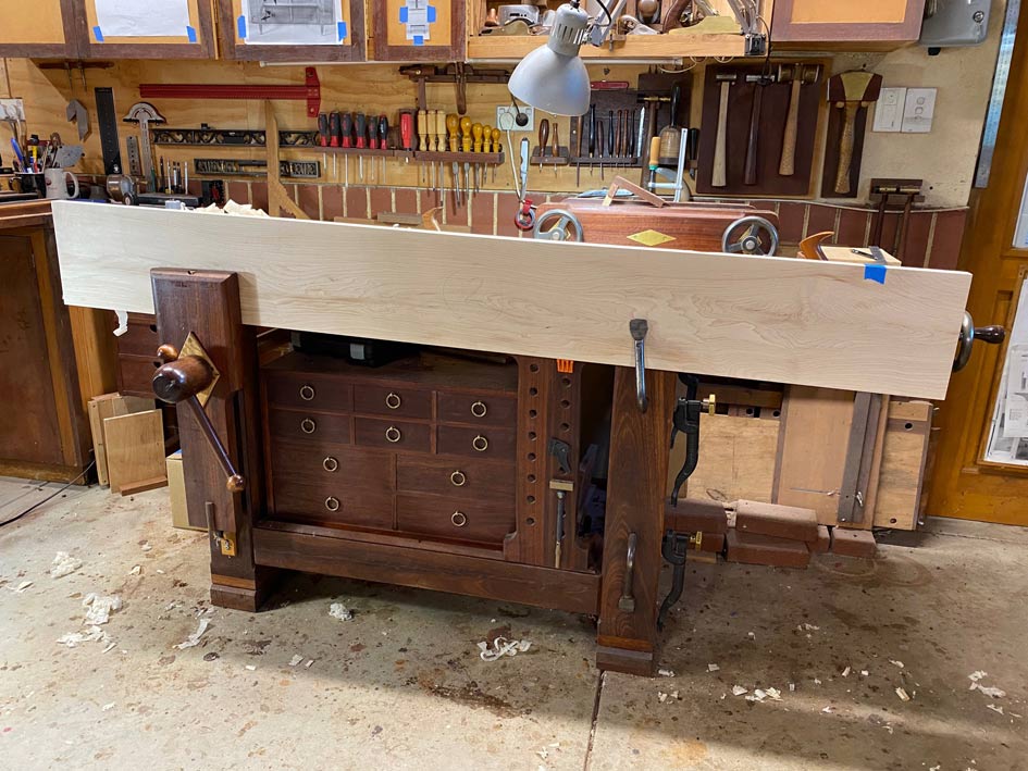
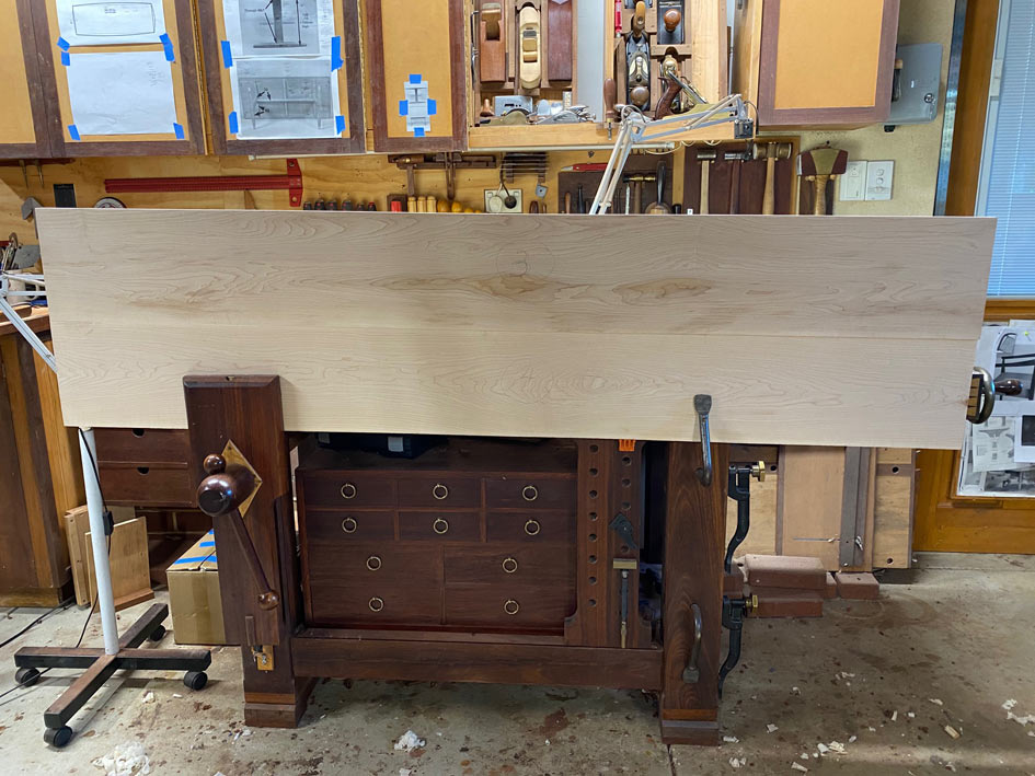
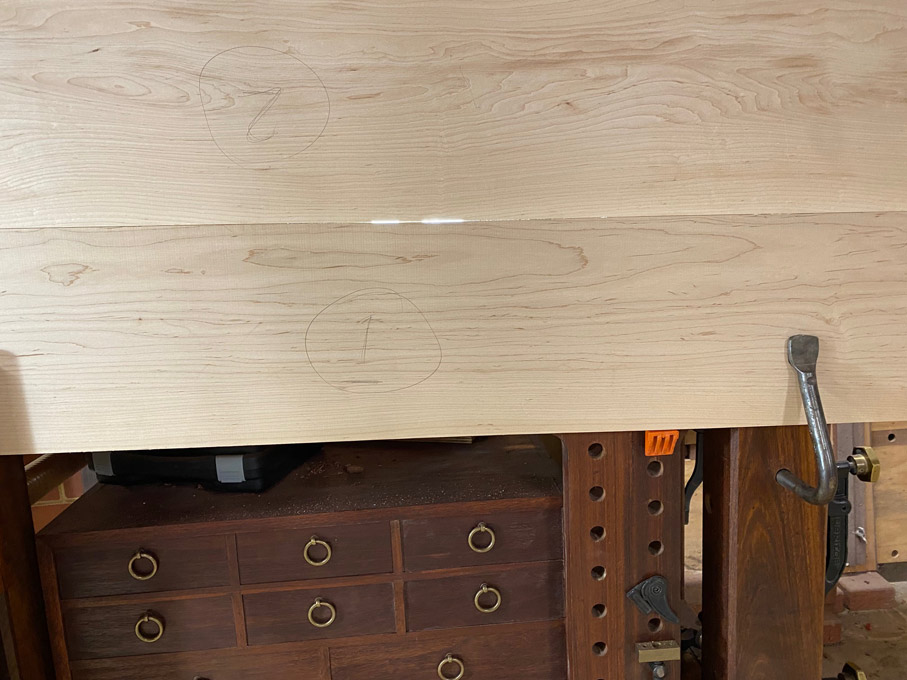
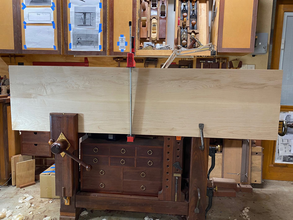
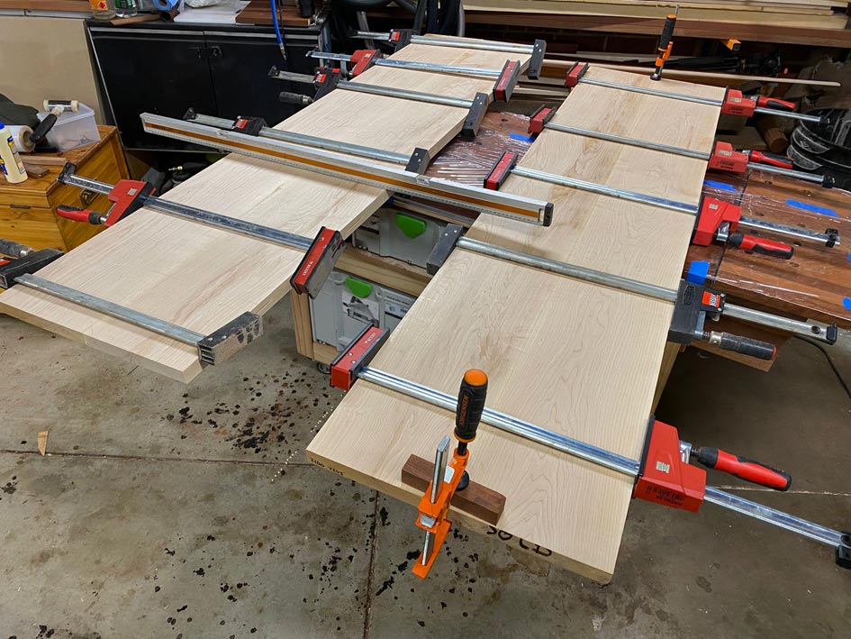
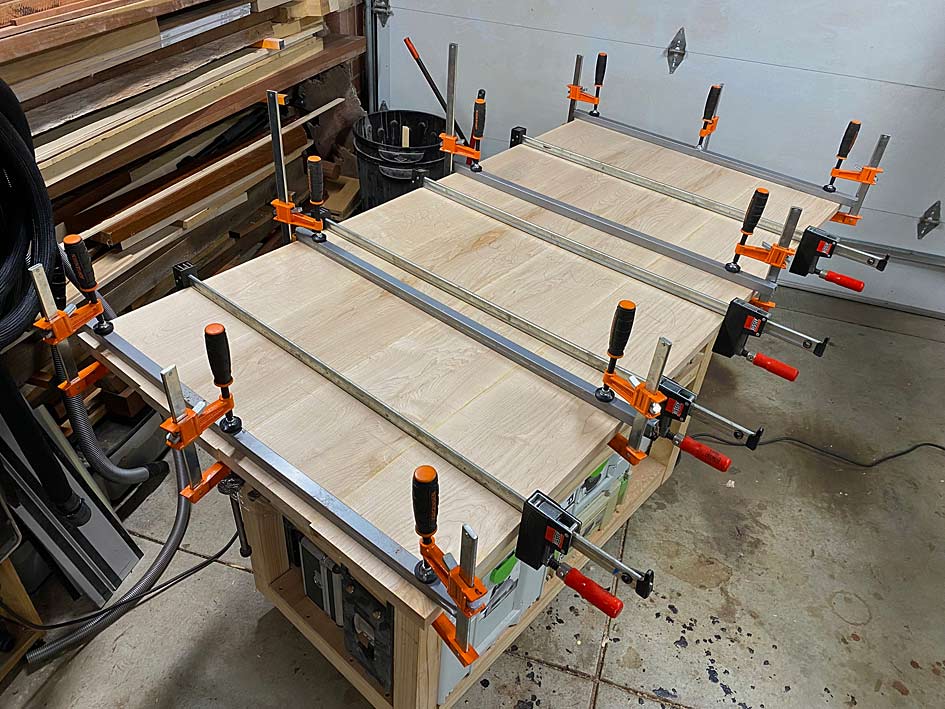
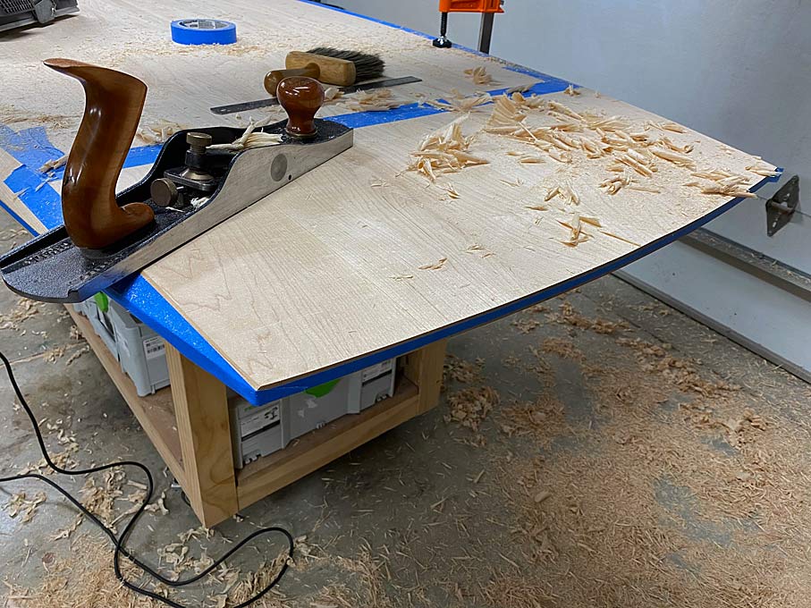
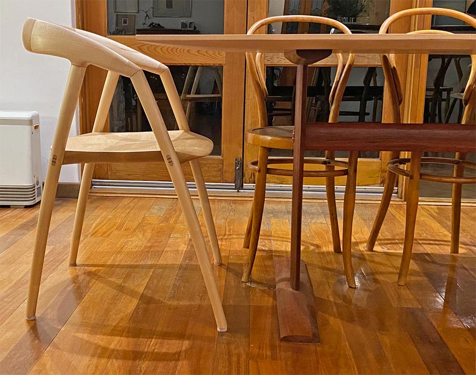
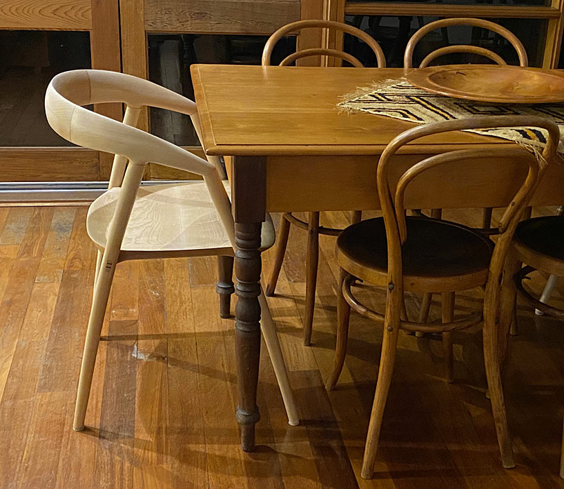
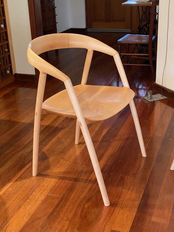
The brief is to build an 8-seater dining table to replace our existing 6-seater. We will retain the 6 vintage bentwood chairs, and I recently completed 2 (DC 09) chairs for use as carvers. Our taste in furniture runs towards the minimalistic, the clean lines of mid century designs from the 1930s, gentle curves. What is needed in a design is a way to link and blend the chairs with the table. In part this will be aided by the wood used for the table top: both the carvers and the top are Rock Maple. Another element will be the presence of the curves in the chairs, which will extend to the table.


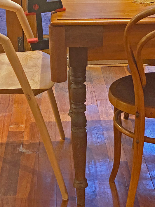
The old table was 200 years old and came with us from from South Africa when we moved to Sydney 40 years ago. The top was Yellow Wood (which resembles an aged Maple), and the legs were Stinkwood (a dark wood). The latter will be represented by Jarrah.

Another need for the new table is that is must be knock-down. We plan to move home in about 18 months, downsizing when I retire. The new home is similar in size, but with less garden to manage. Being knock-down cannot impose on the design, and cannot impact on the rigidity of the construction. Today I will show you what I came up with.

The old table was 1350mm (53") long, 850mm (33 1/5") wide and 775mm (30 1/2") high.


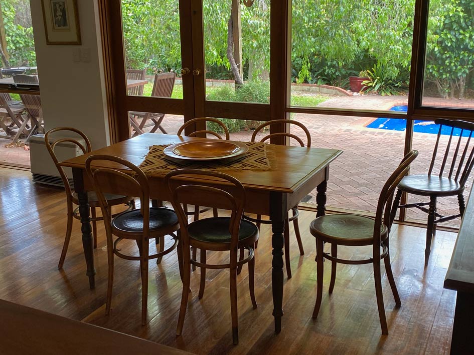
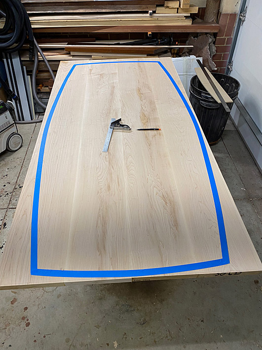
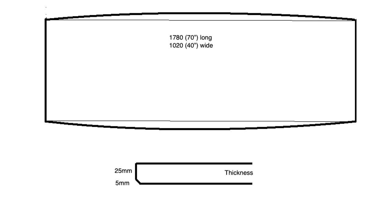
The new table will be 1780mm (70") long, 1020mm wide (40"), and 760mm (30") high.


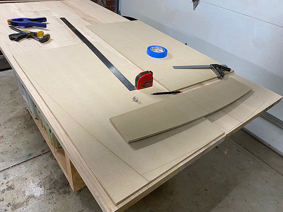
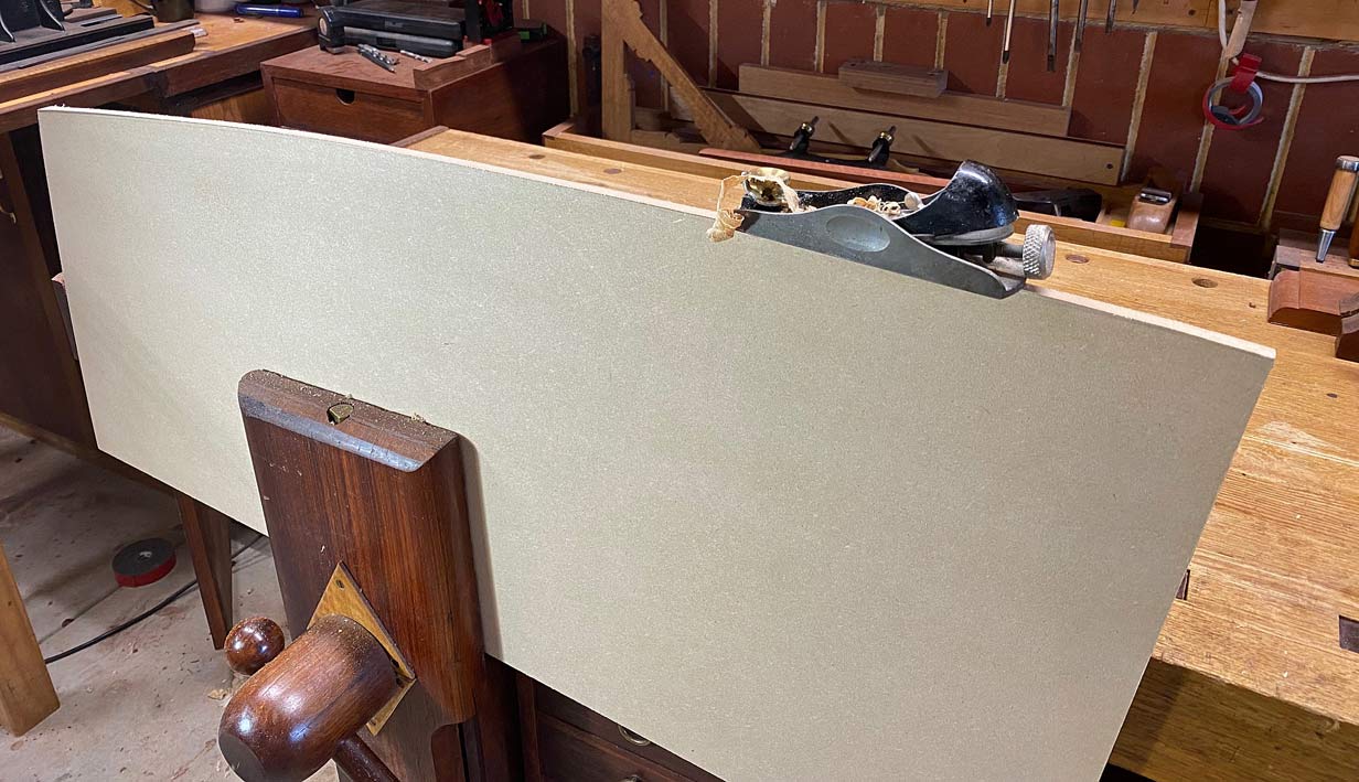
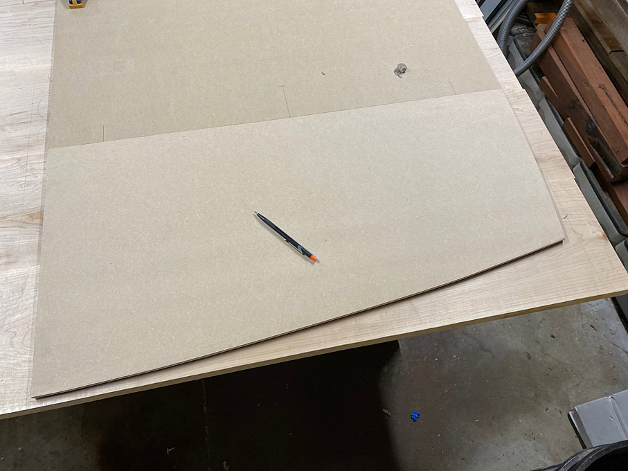
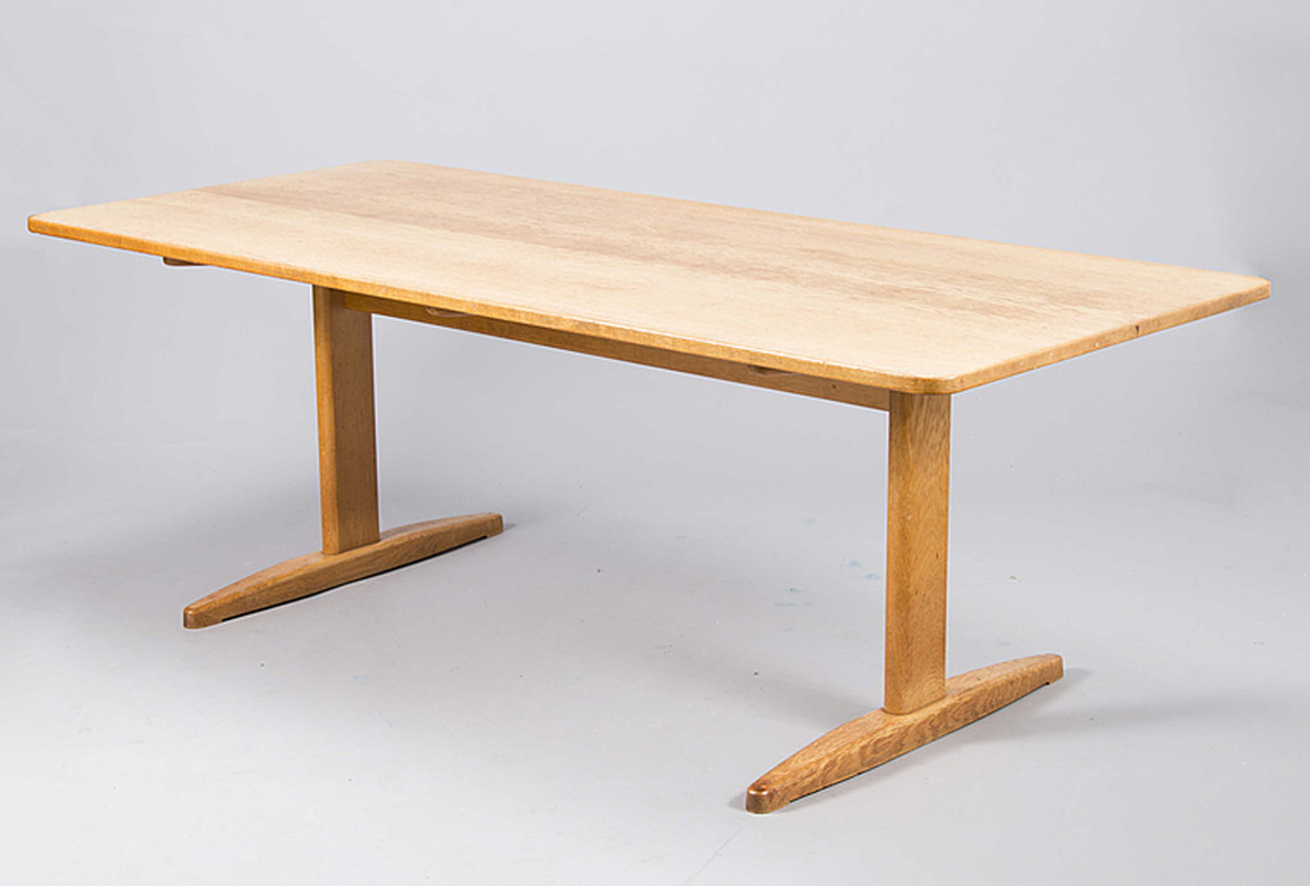
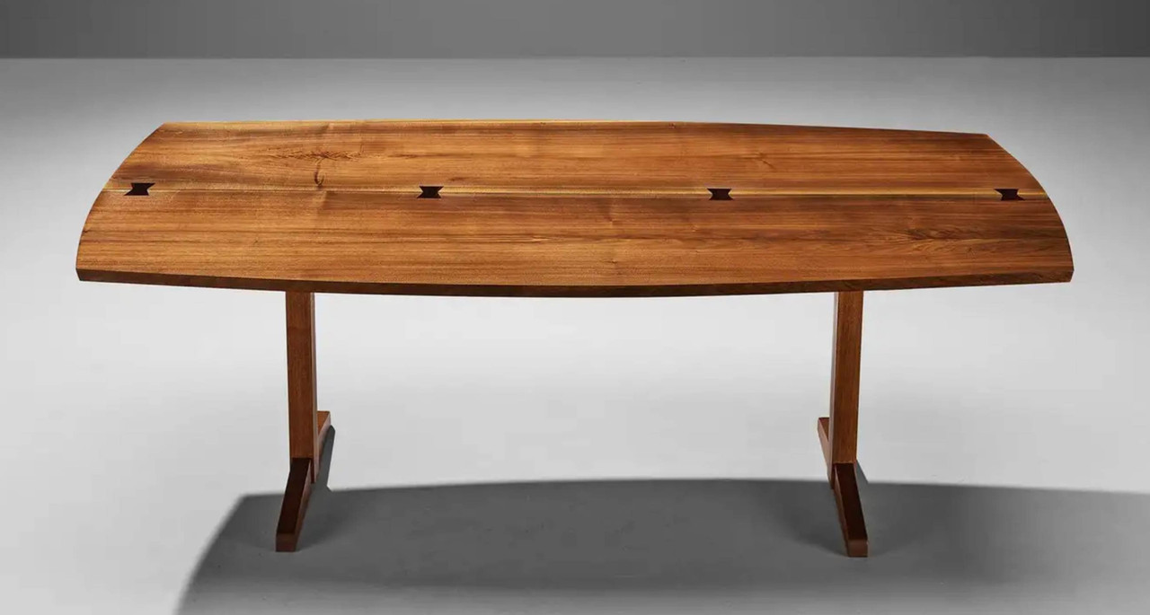
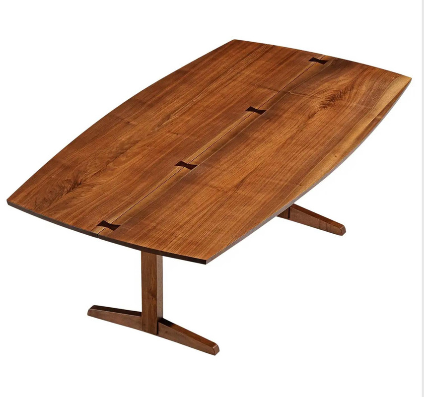
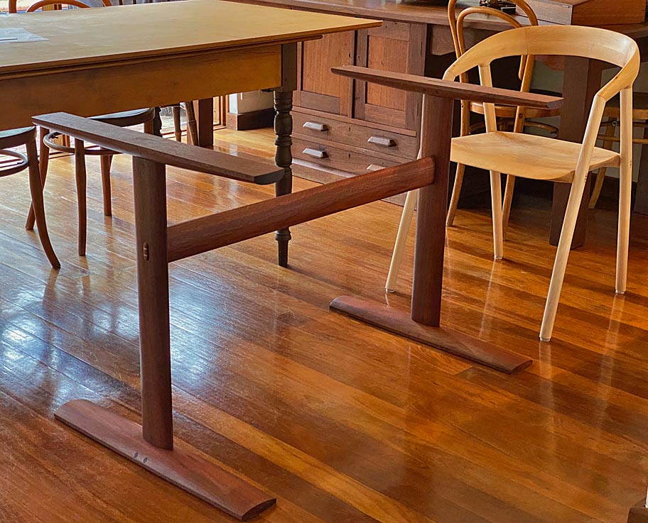
I found a photo of a table with similar proportions. This table has rectangular legs, but its silhouette creates the illusion that the legs are round, which will be the case in this build.


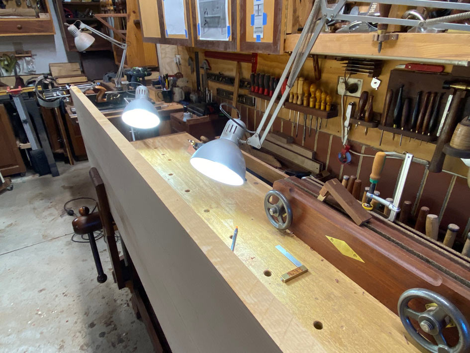
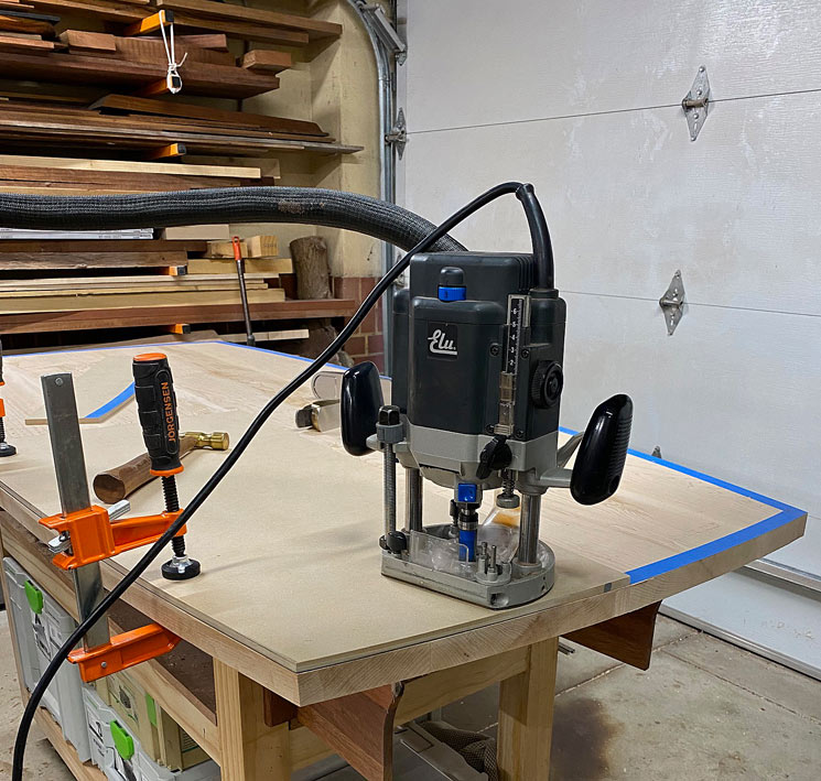
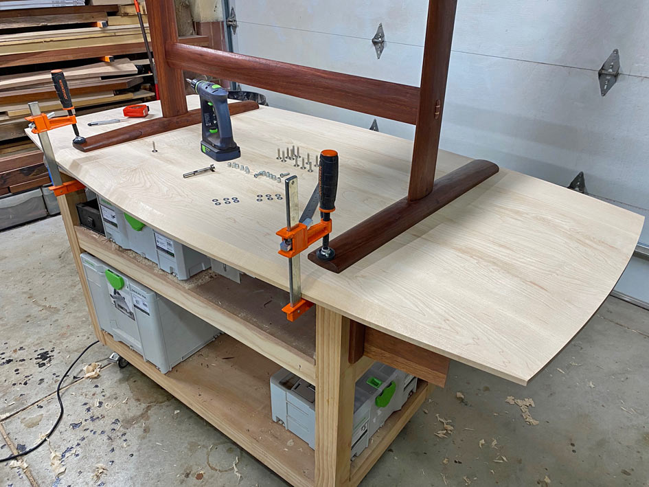
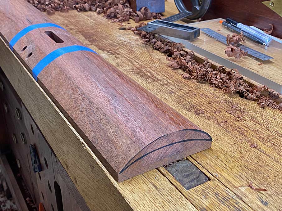
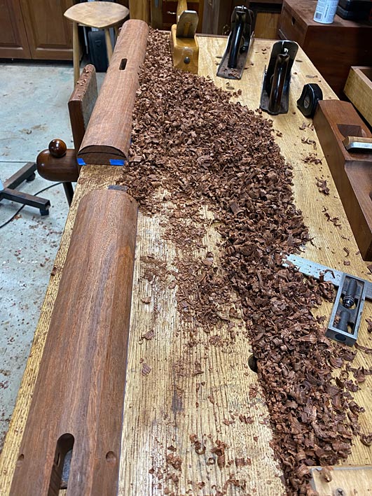
When I began test-building the leg-rail build, the legs were to have a 75mm (3") diameter with a rail of similar width. The legs ended up too chunky, and were subsequently reduced to 60mm (2 3/8") diameter. I am considering reducing the rails to 60mm as well (they are 75mm in the photos), but am concerned about a drop in rigidity. Having stated this, the rails are 30mm wide, Jarrah, and this is quite substantial.

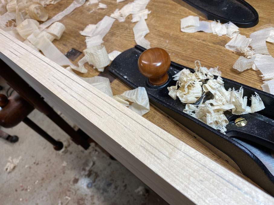
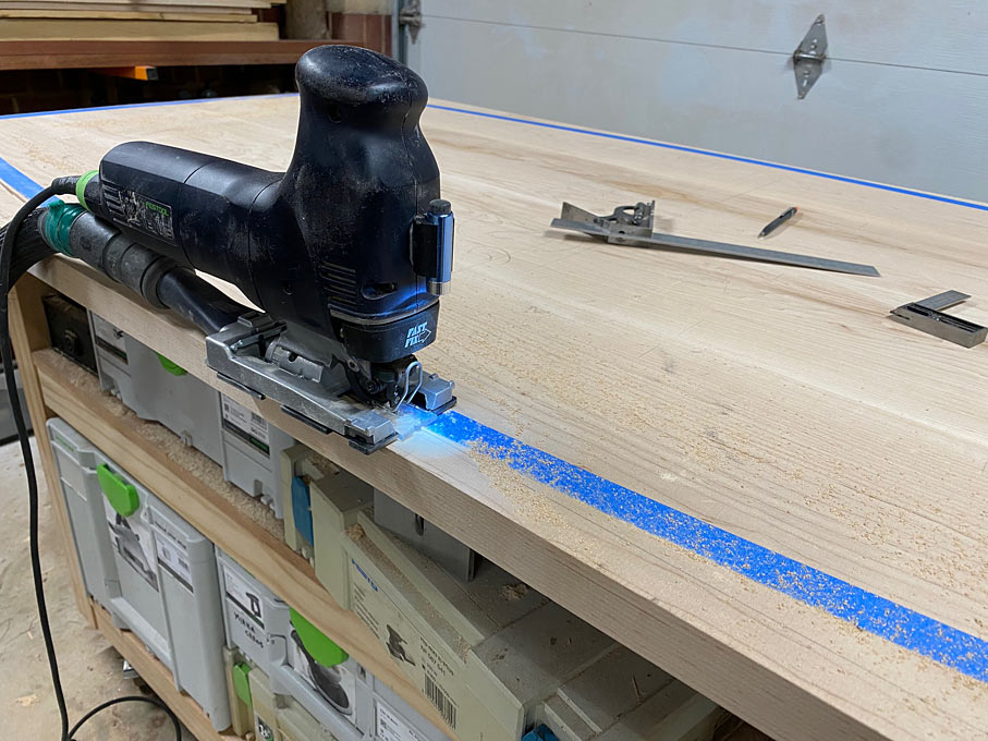
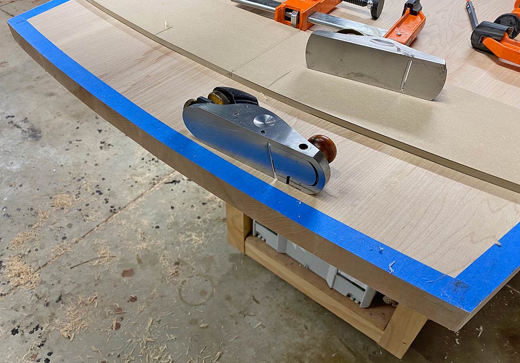
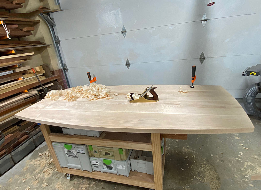
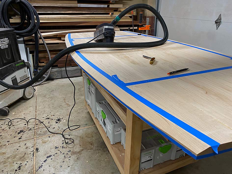
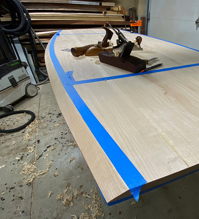
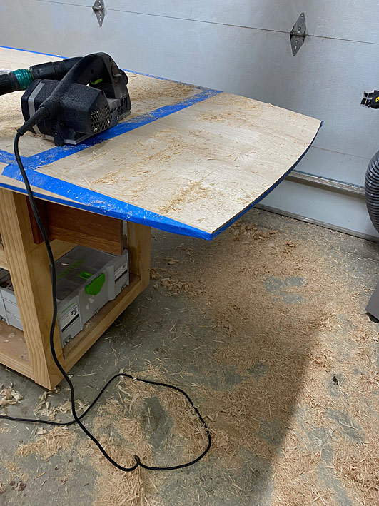
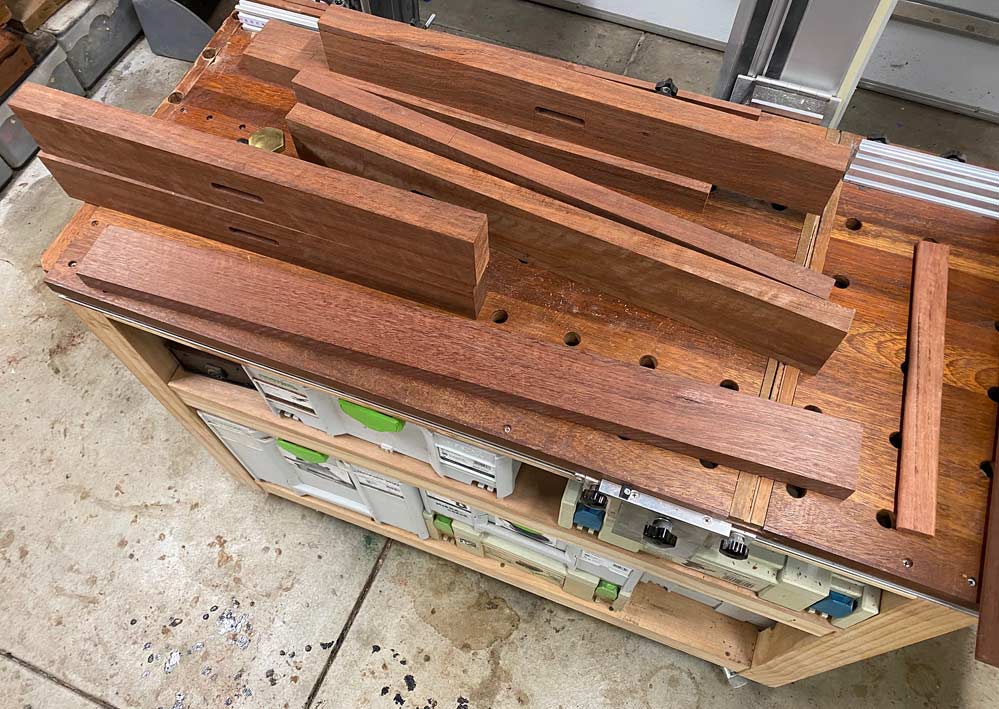
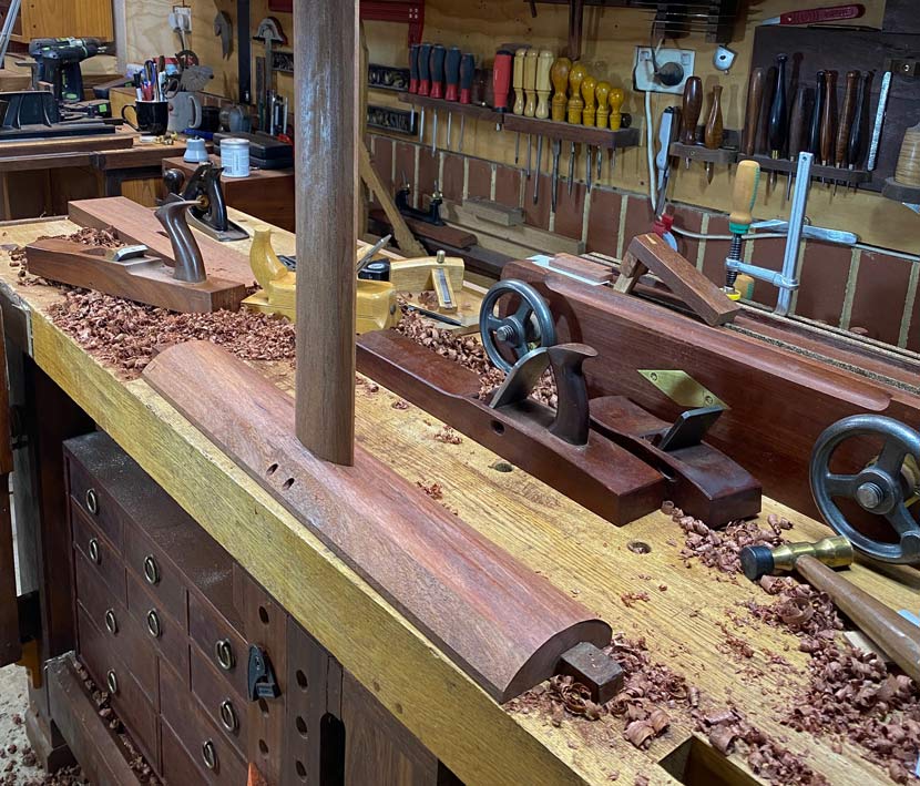
So to the construction ...


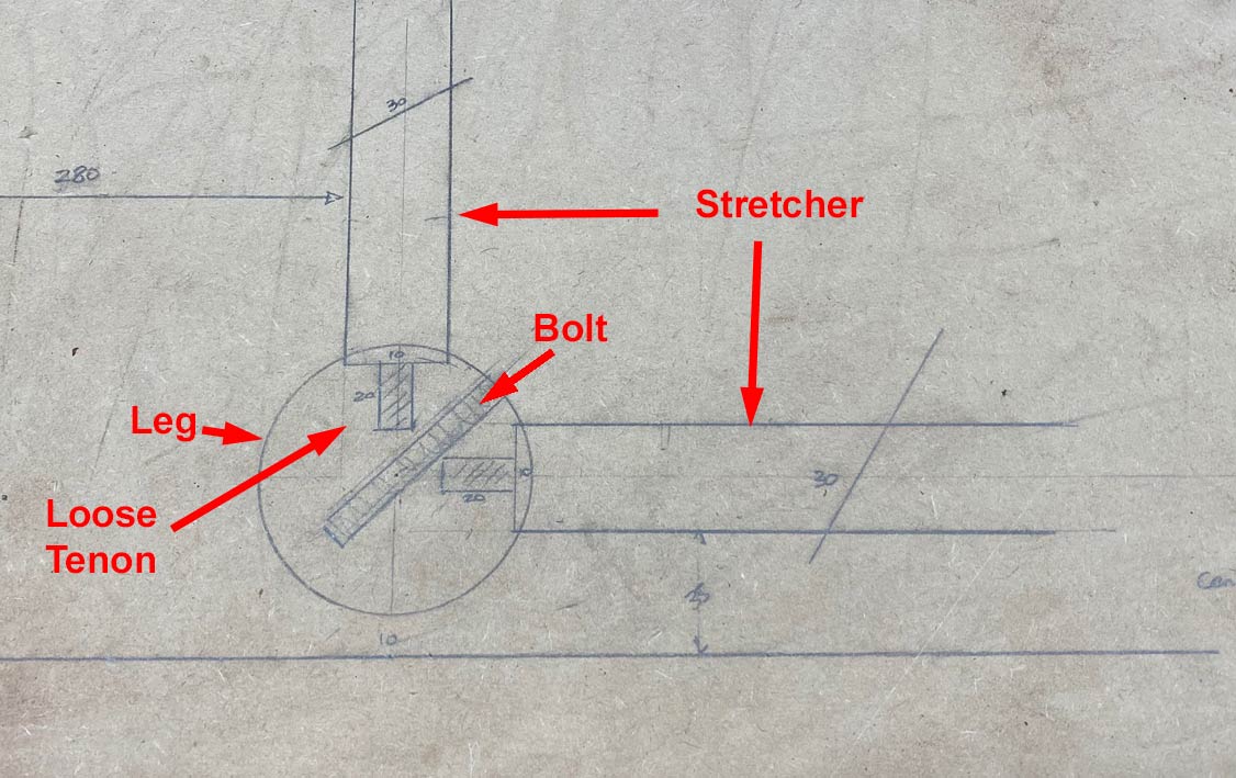
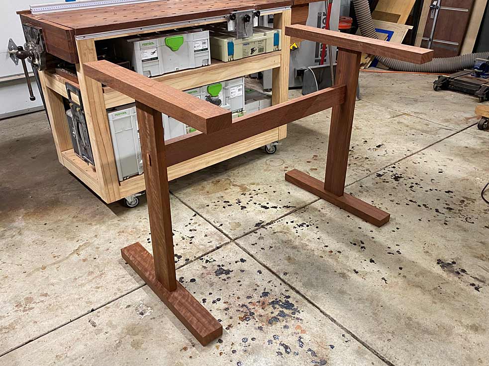
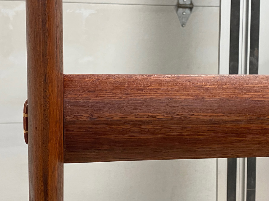
The rails (or stretcher) are connected to the legs with loose tenons. The tenons are glued to the end of the rails, but left unglued when connected to the legs.

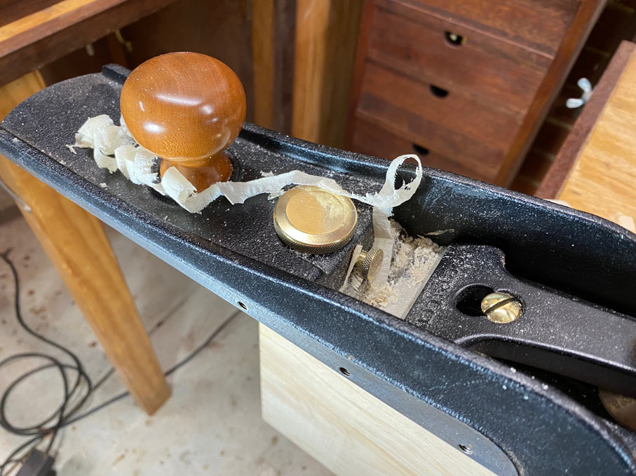
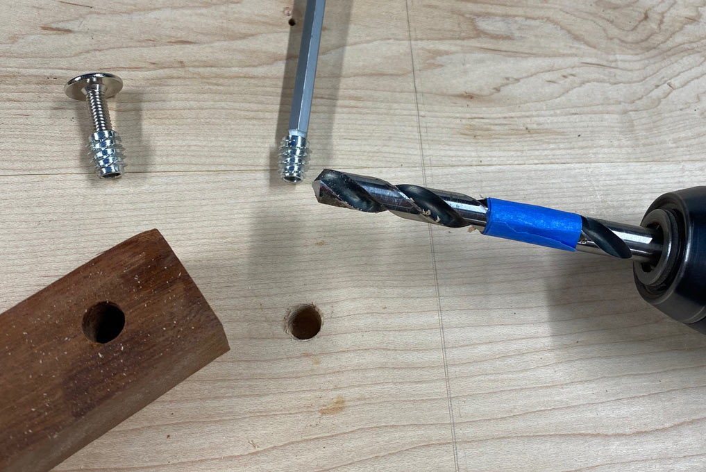
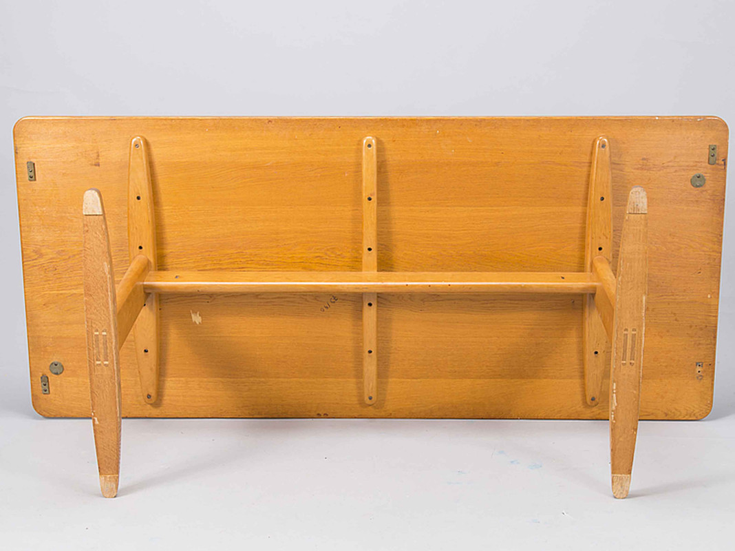
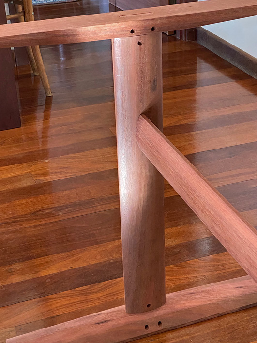
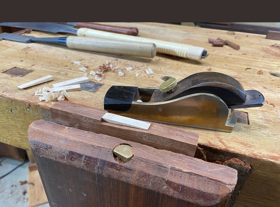
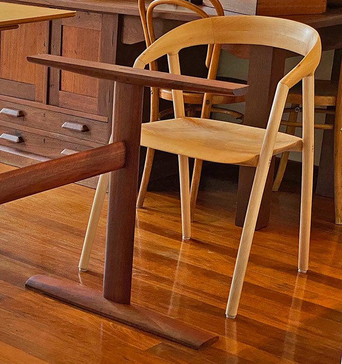
To facilitate the knock-down, a steel mechanical connector is being used ...


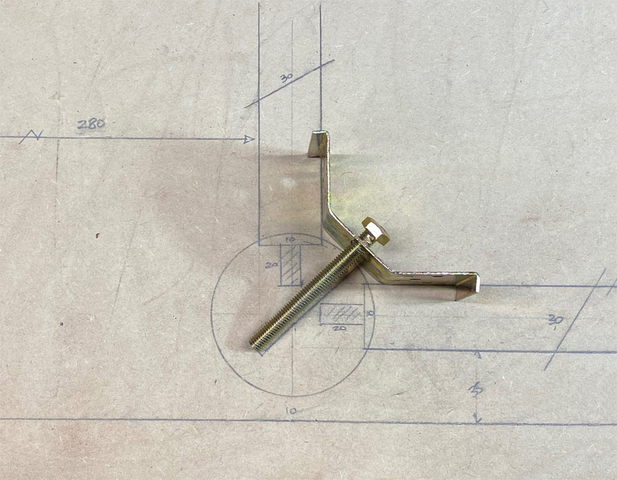
This requires the leg being tapped for a bolt, with the connector also screwed to the rails.

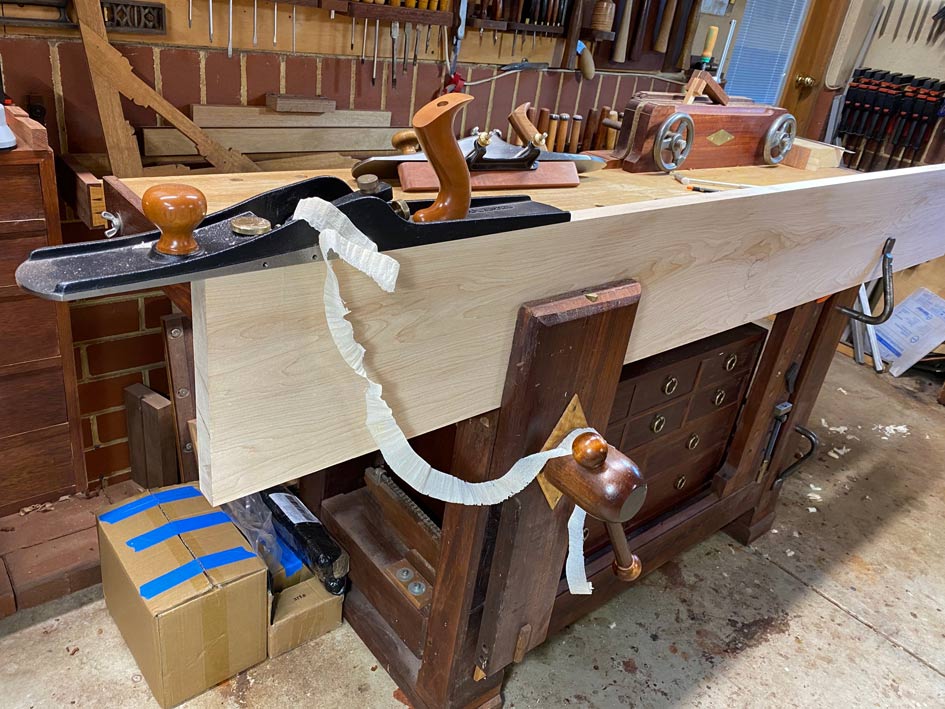
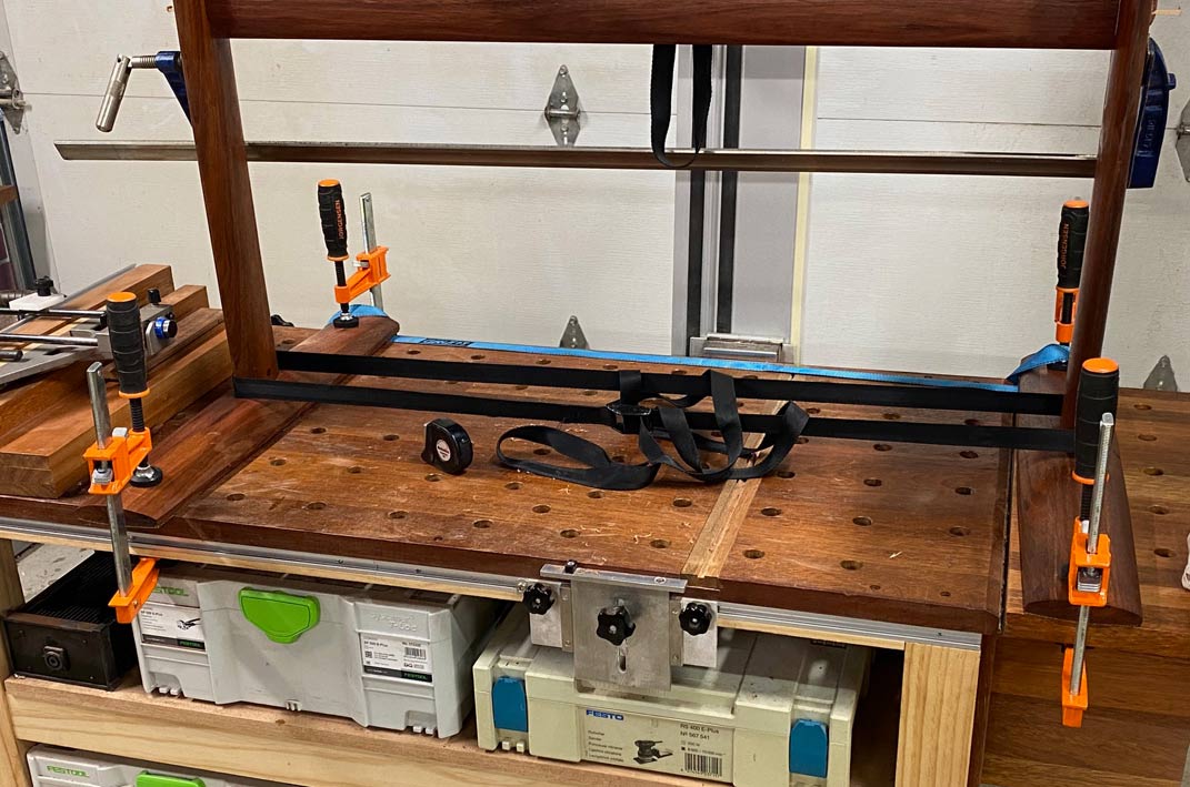
What follows is testing this out (some of the photos here have 75mm wide legs).

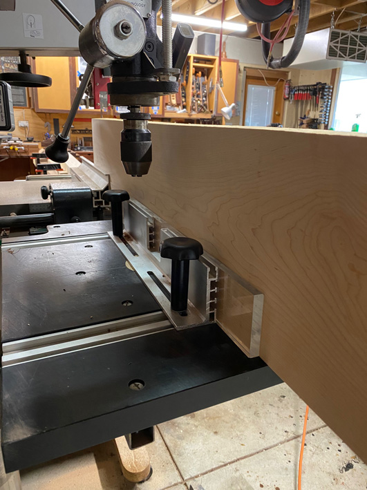
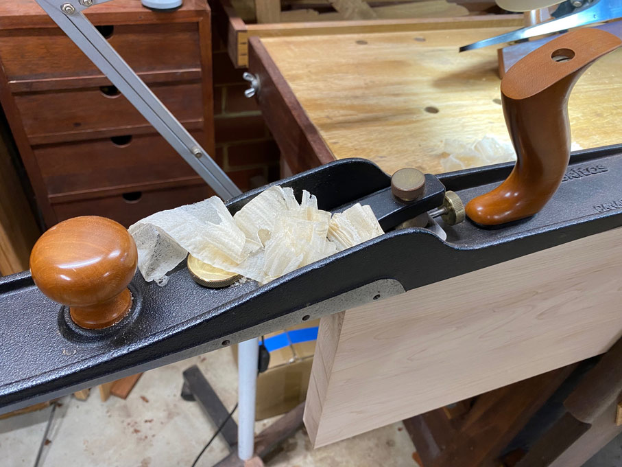
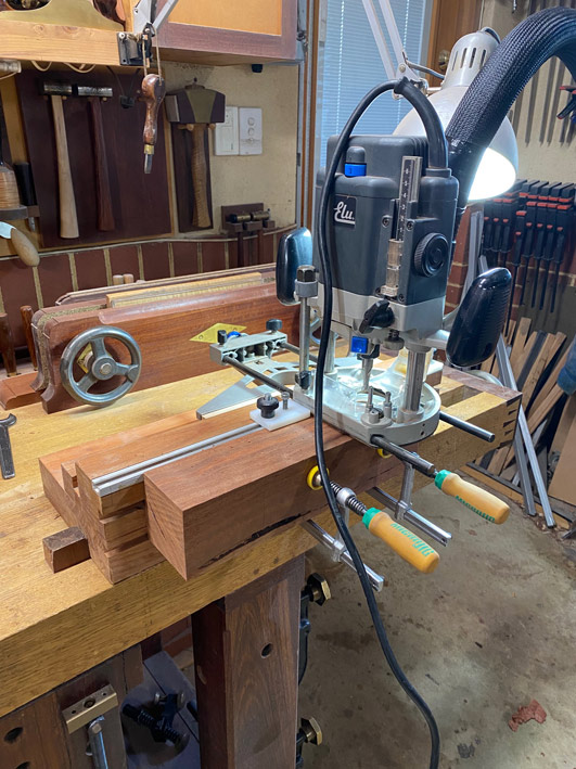
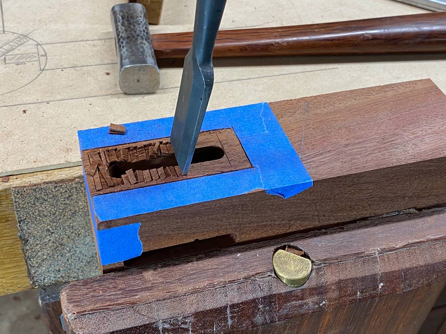
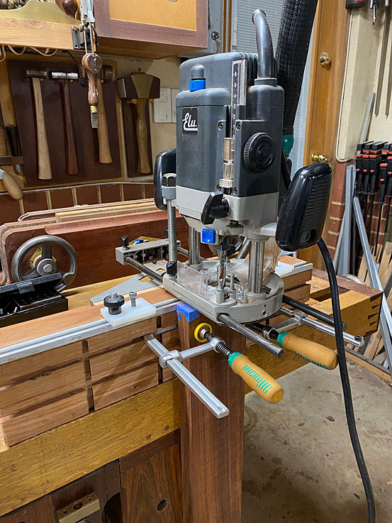
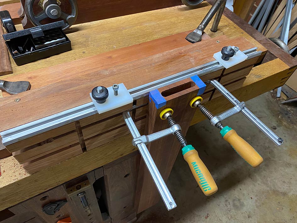
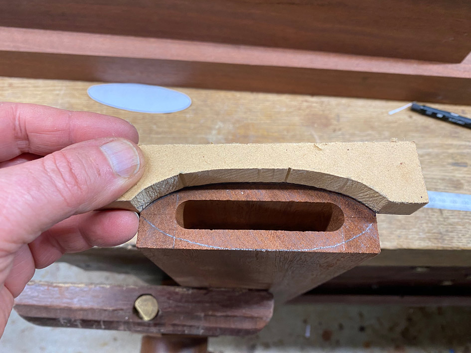
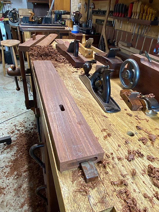
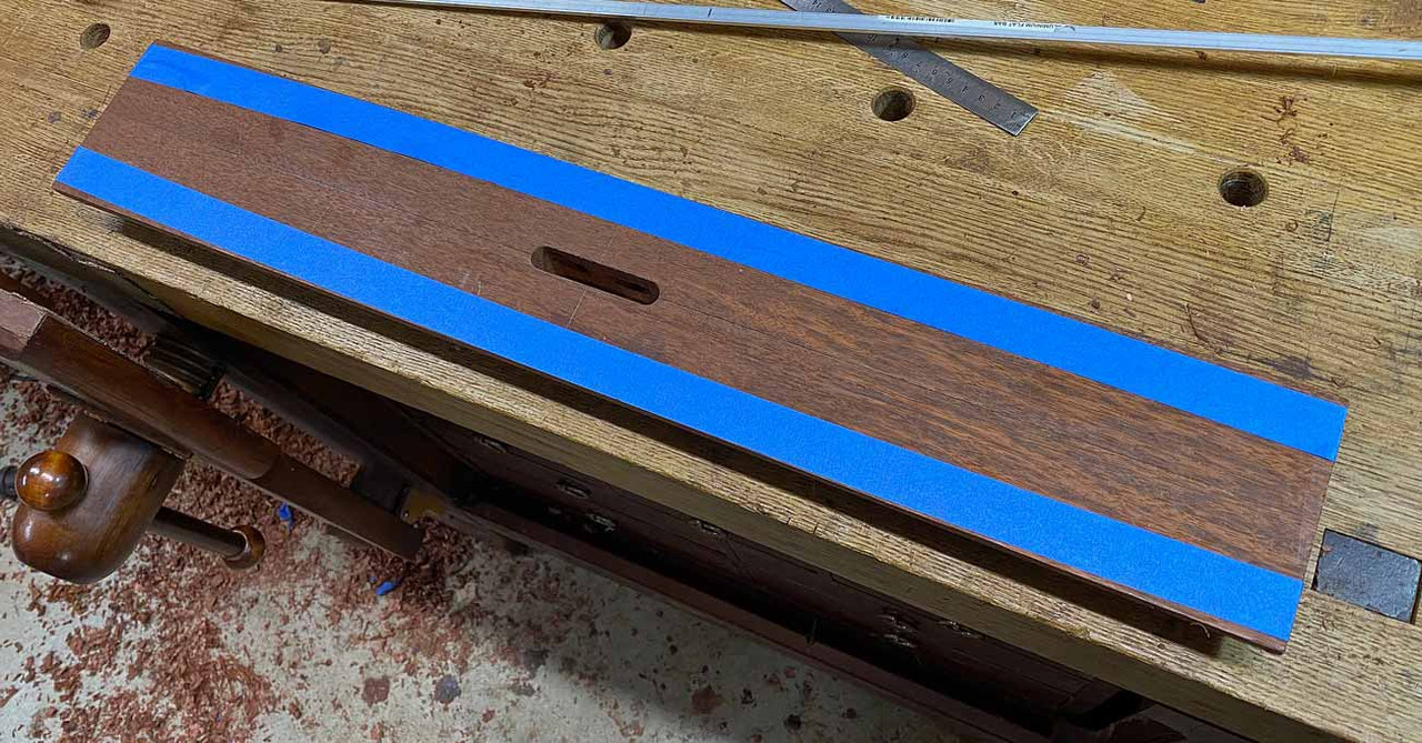
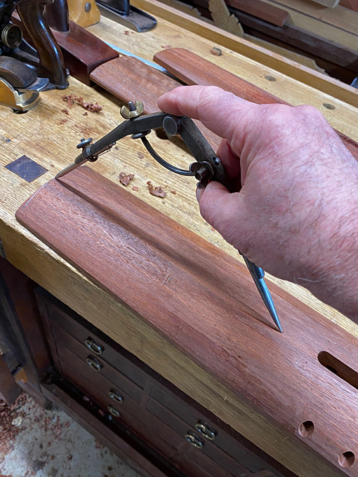
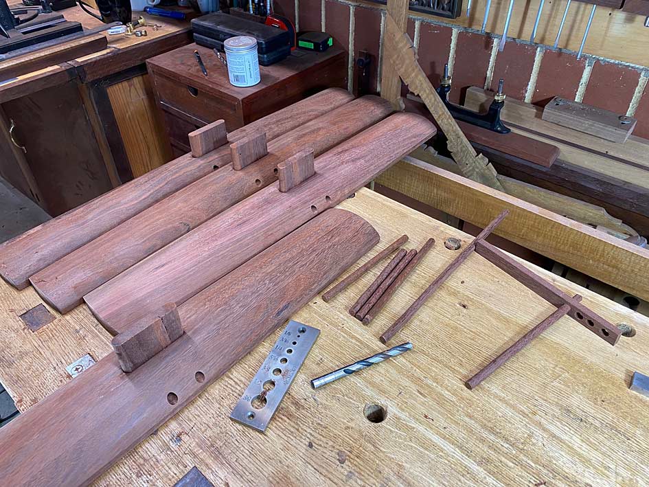
The 10mm x 55mm mortises in the legs were made with a router, and those in the rails made with a Domino.


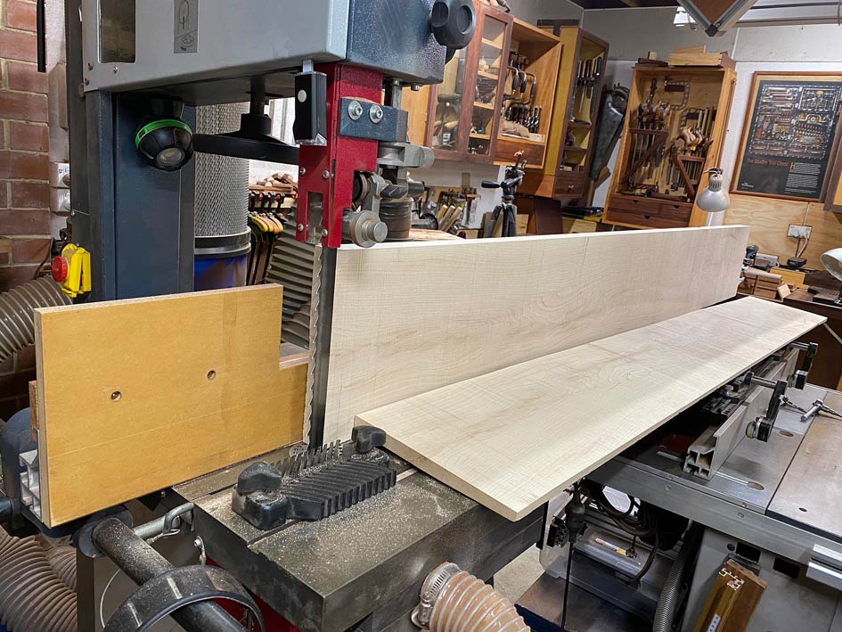
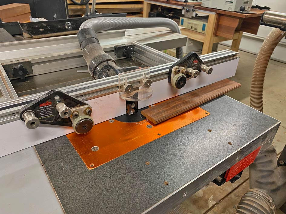
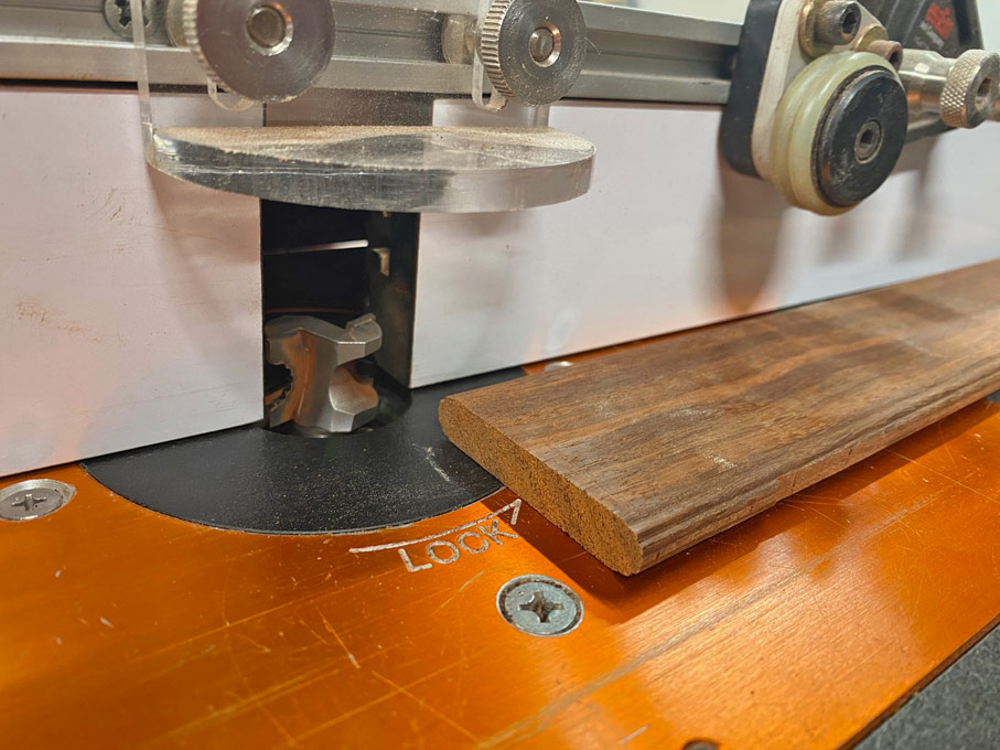
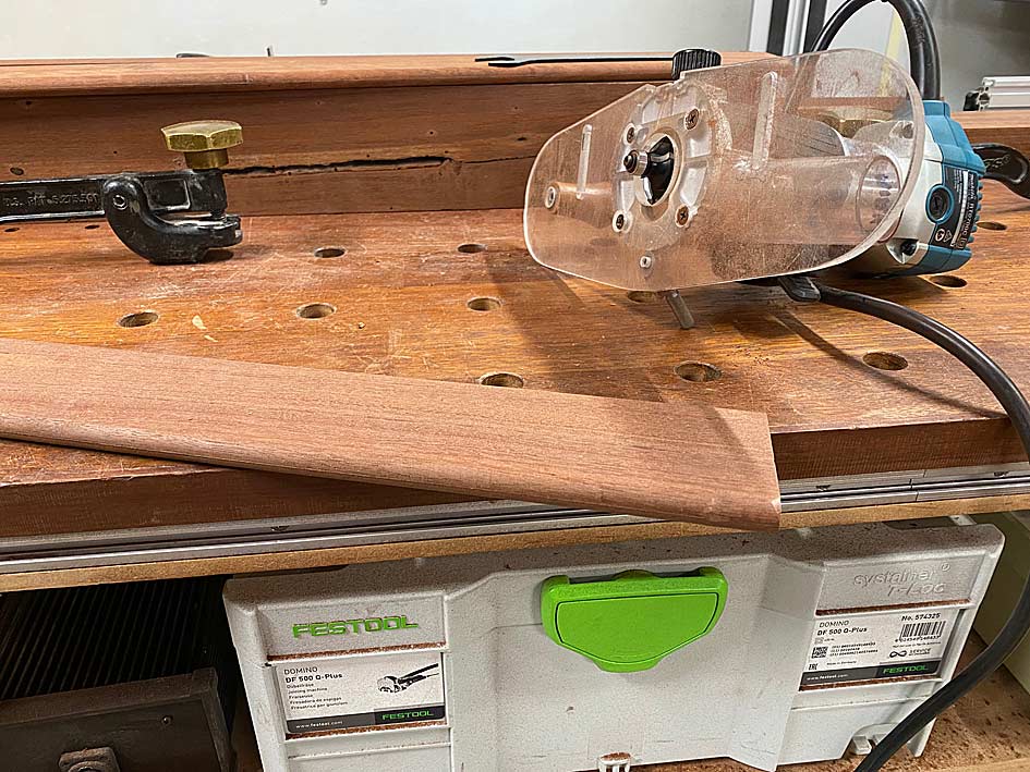
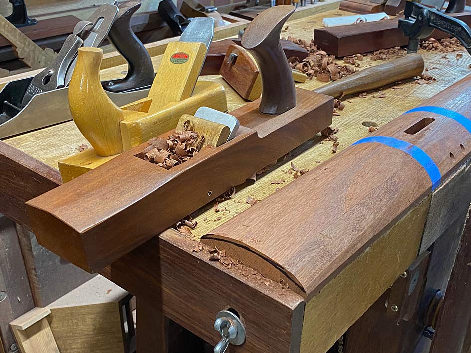
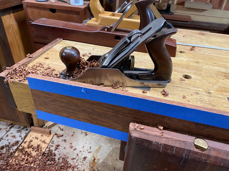
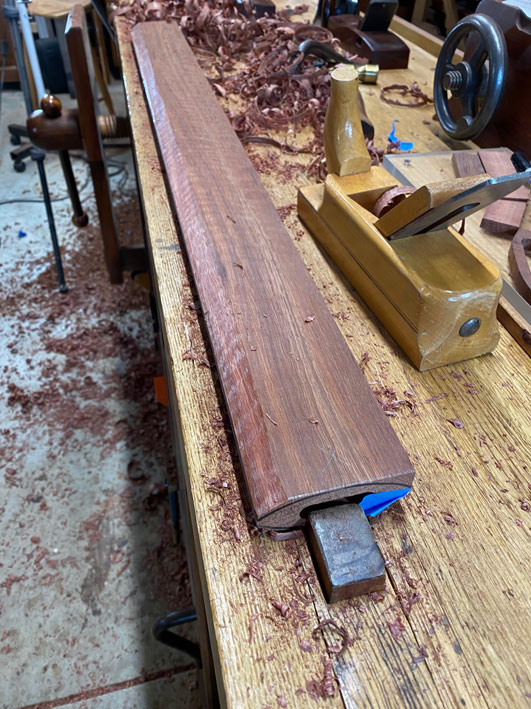
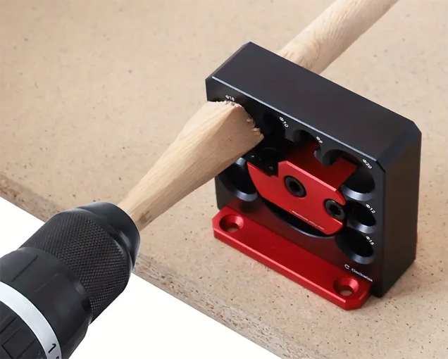
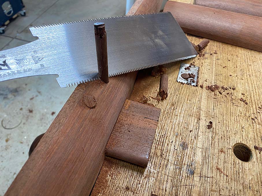
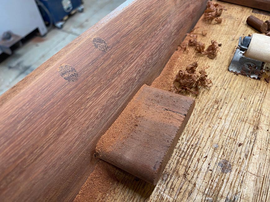
The loose tenons were shaped on the router table using the new Woodpecker router bits ...


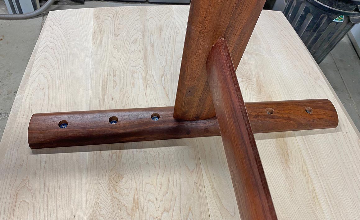
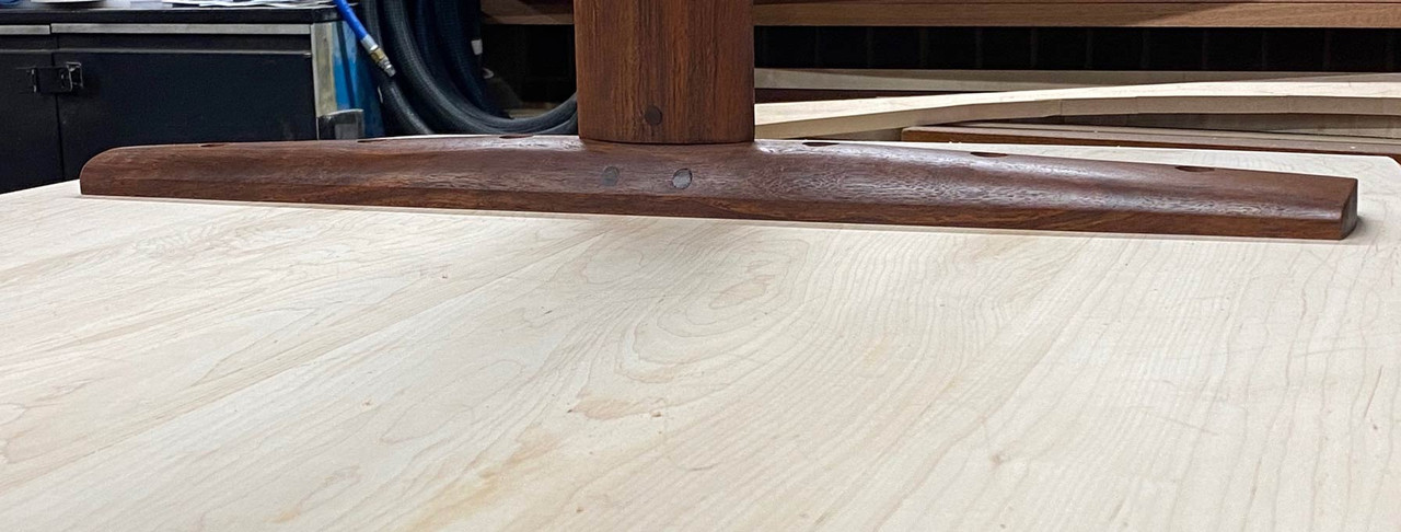
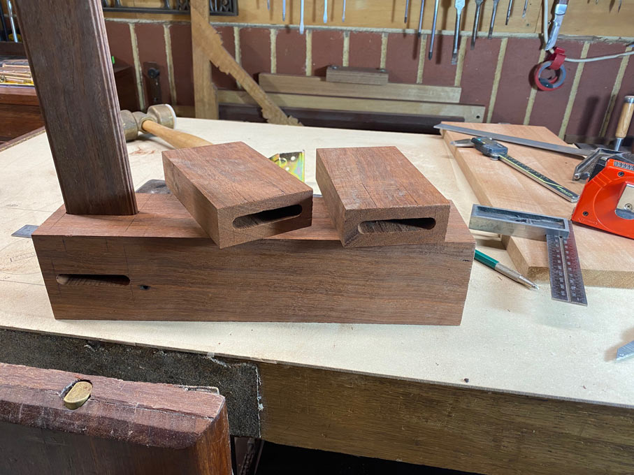
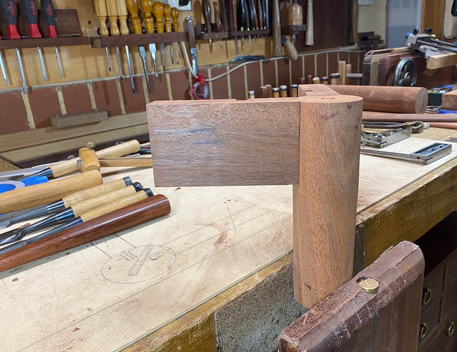
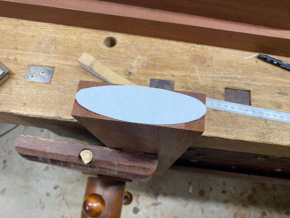
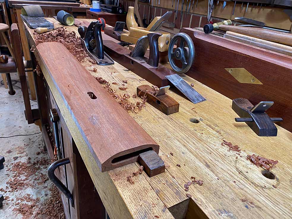
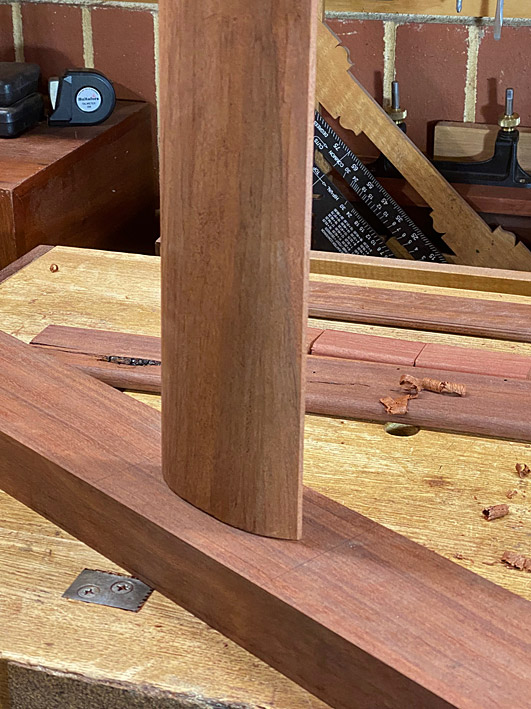
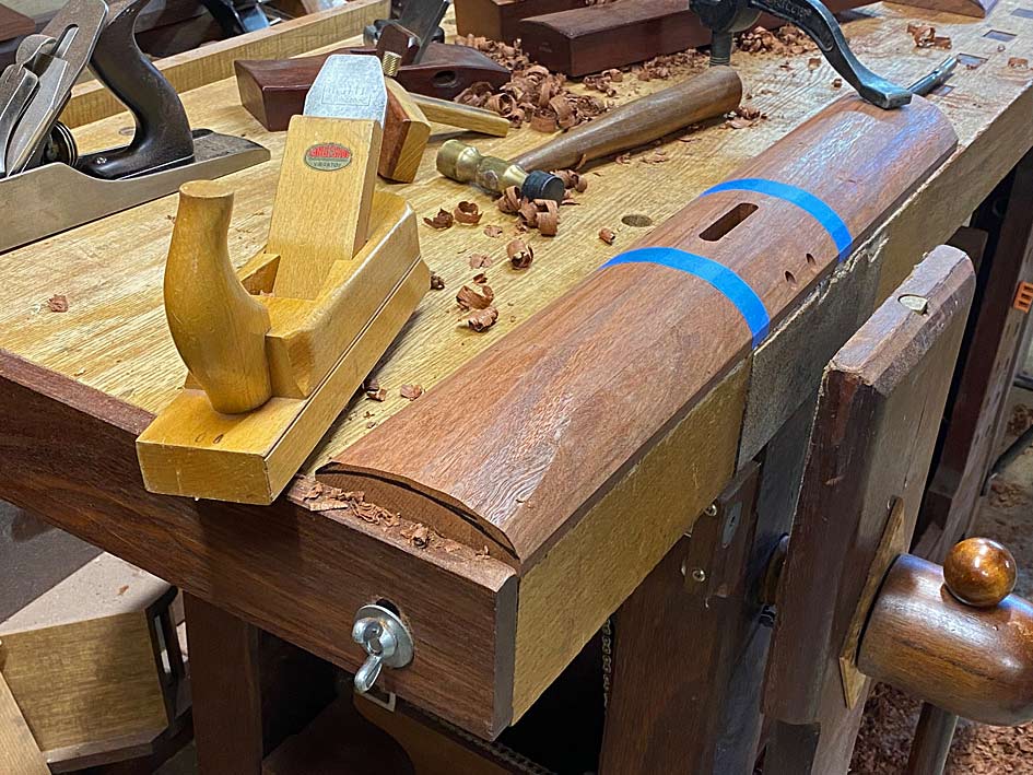
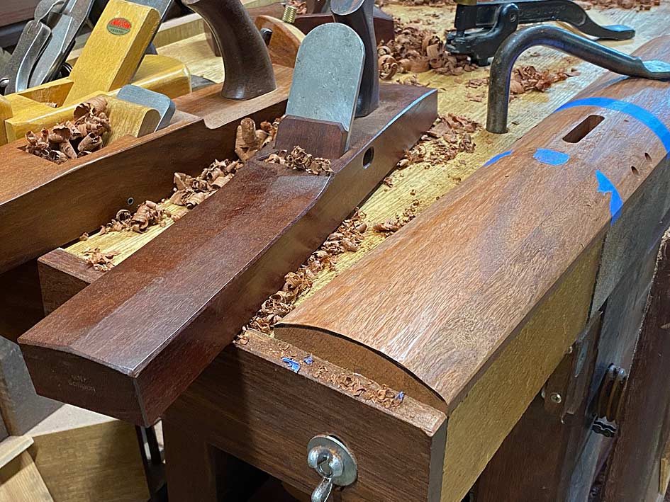
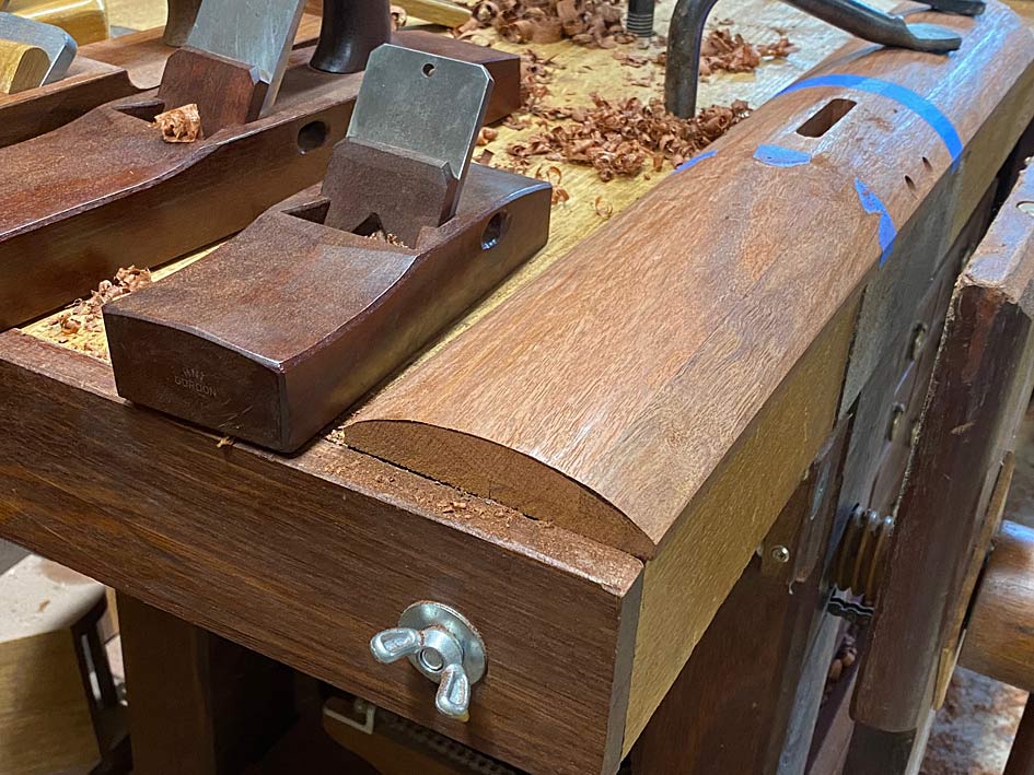
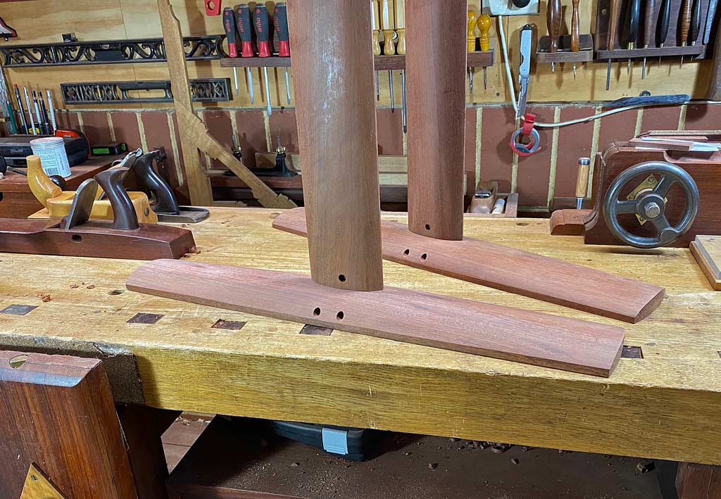
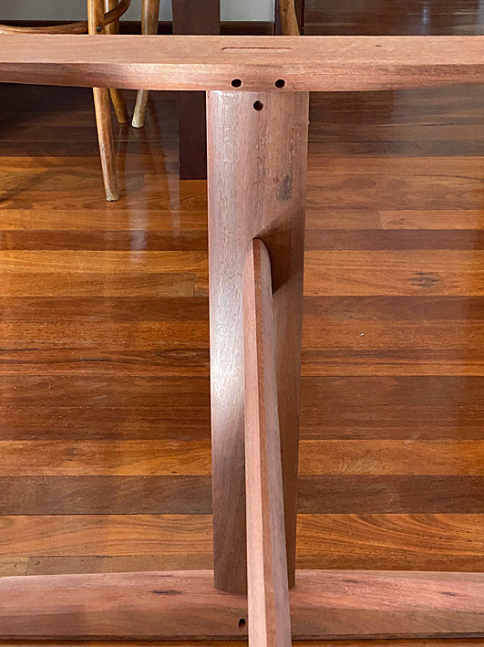
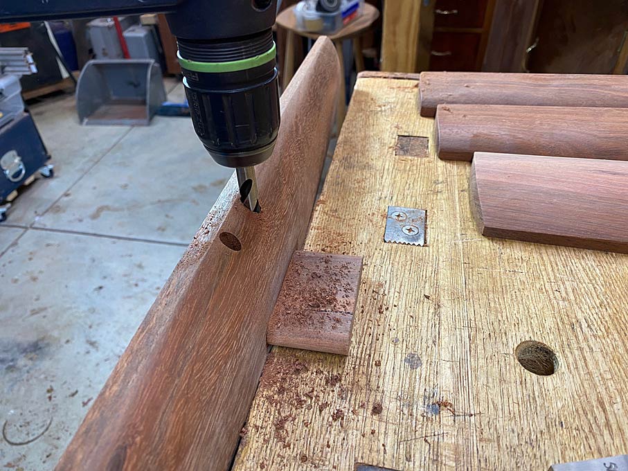
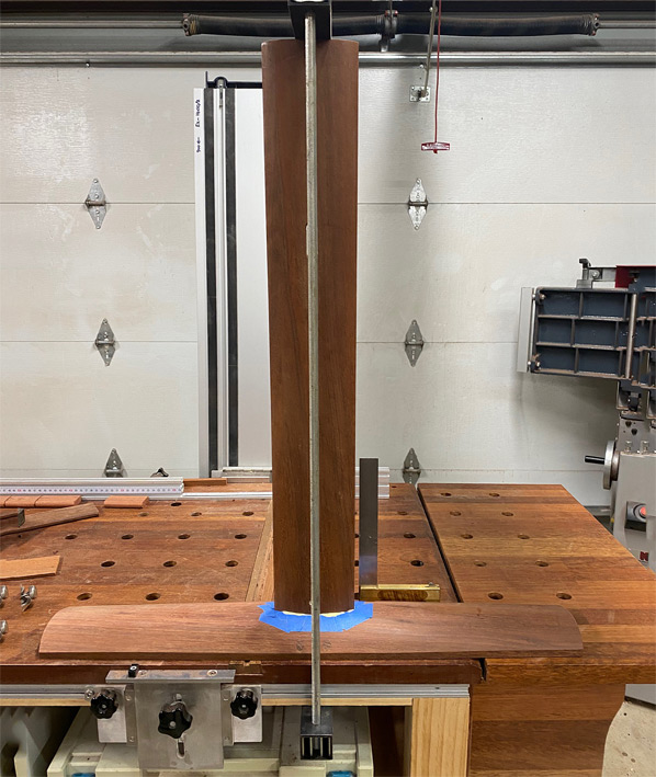
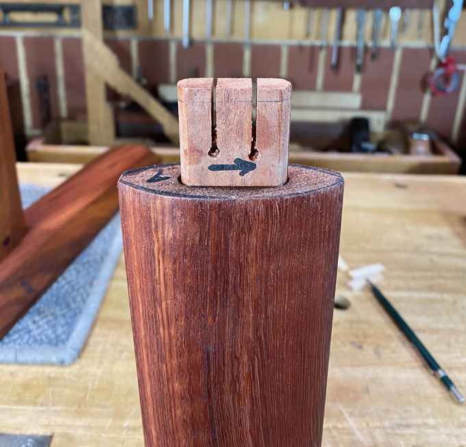
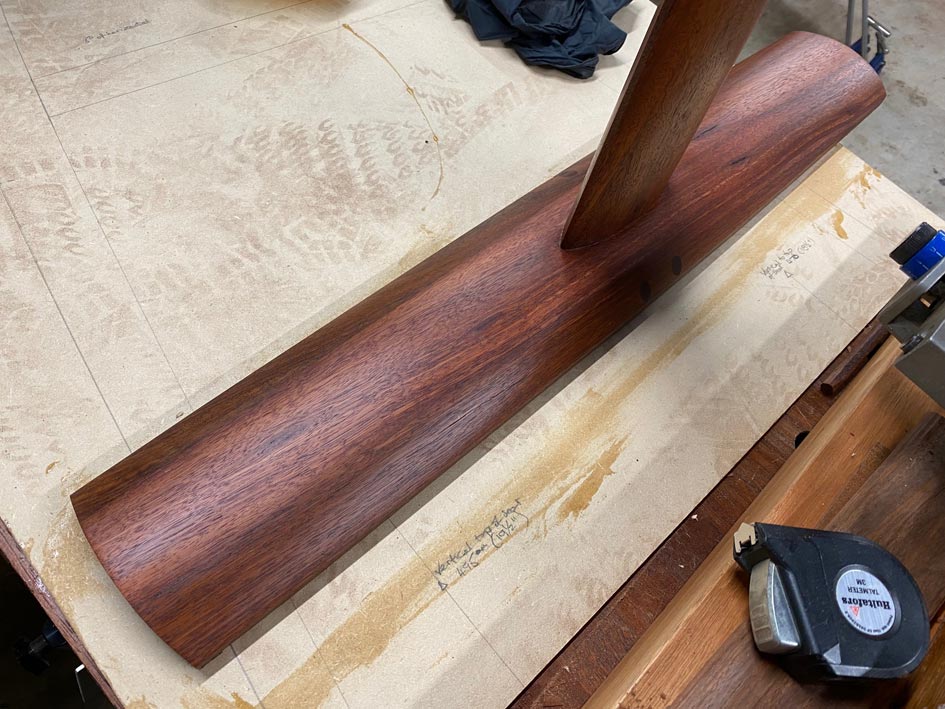
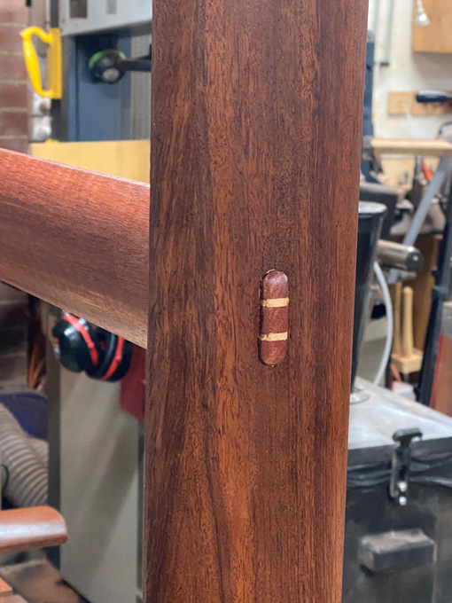
The legs were also mortised for the rails, themselves, to mate the two flush. Here I have gone down to a depth of 5mm.


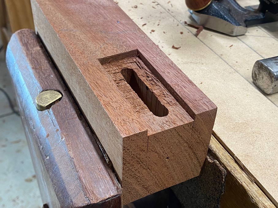
This looks fine here ...


... but in future I shall mortise to a depth of 7mm. Once the leg is turned, there is minimal beauty depth ...


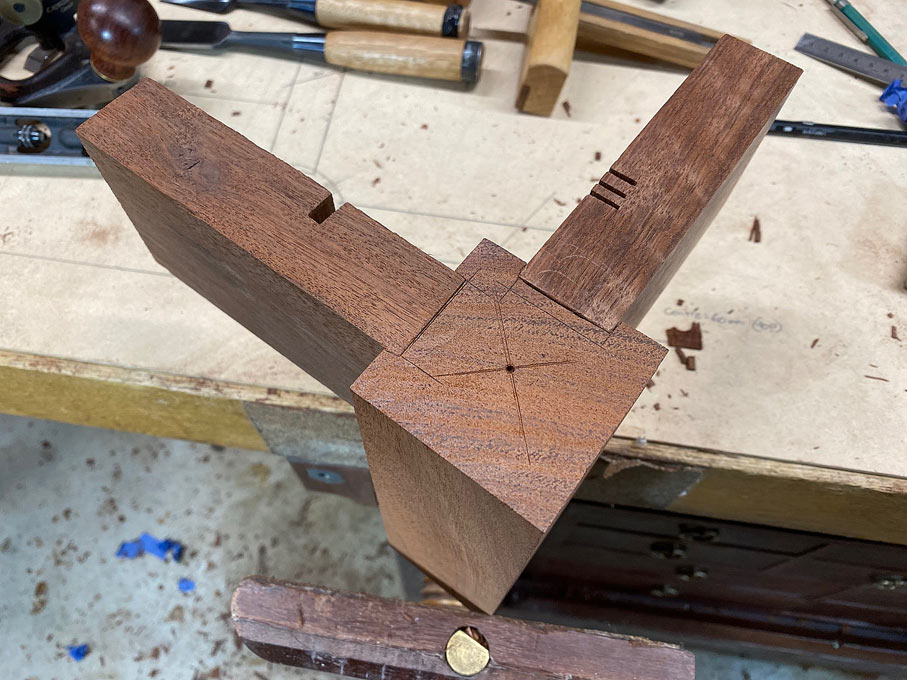
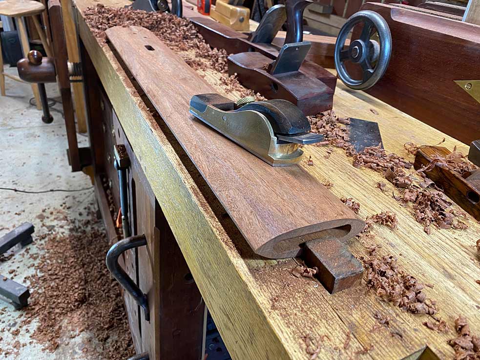
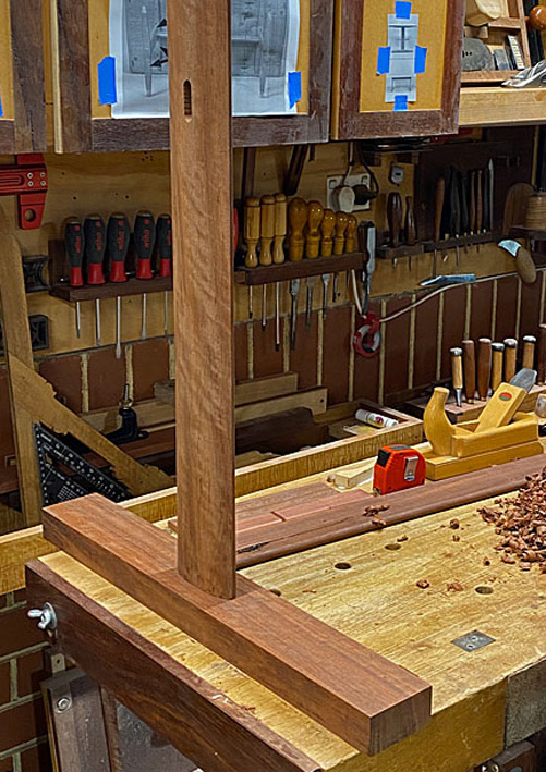
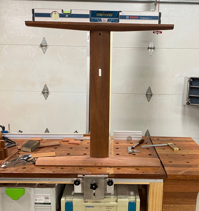
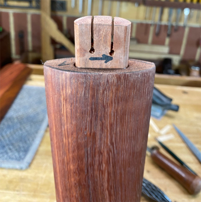
With the connector (ignore the chewed look - this was the result of trial-and-error) ...


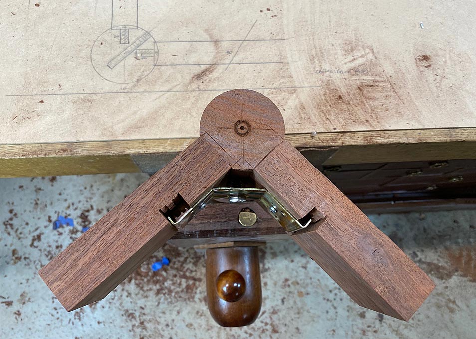
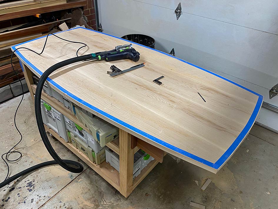
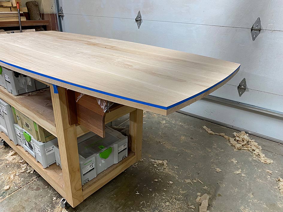
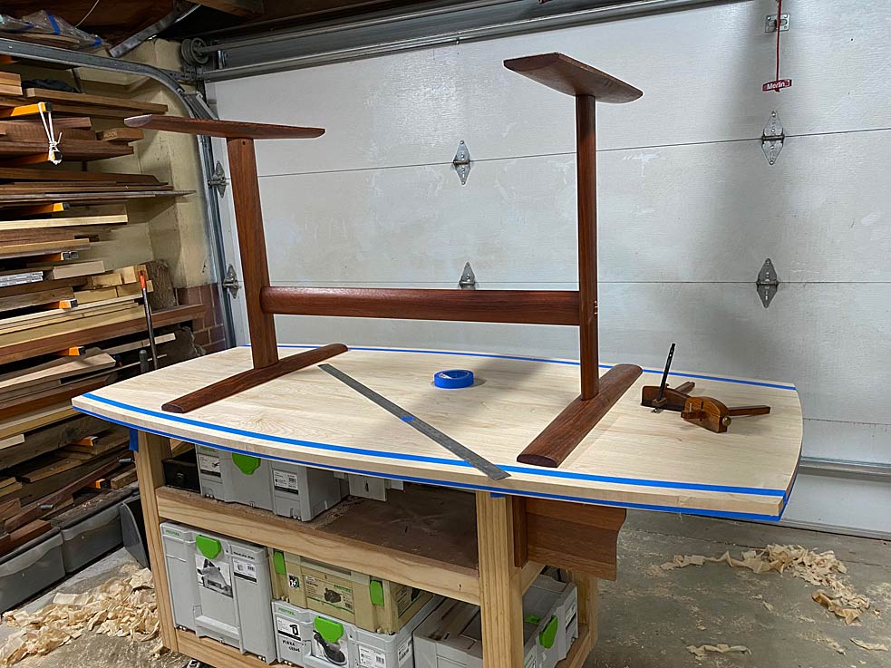
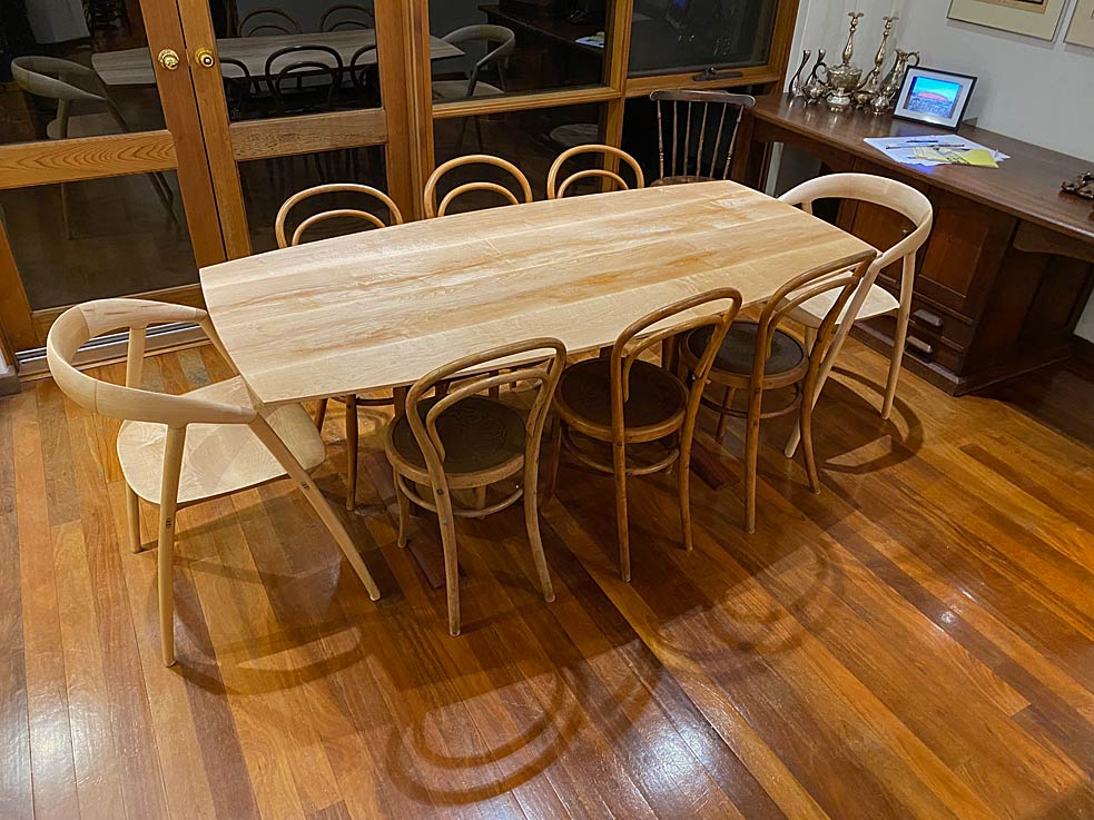
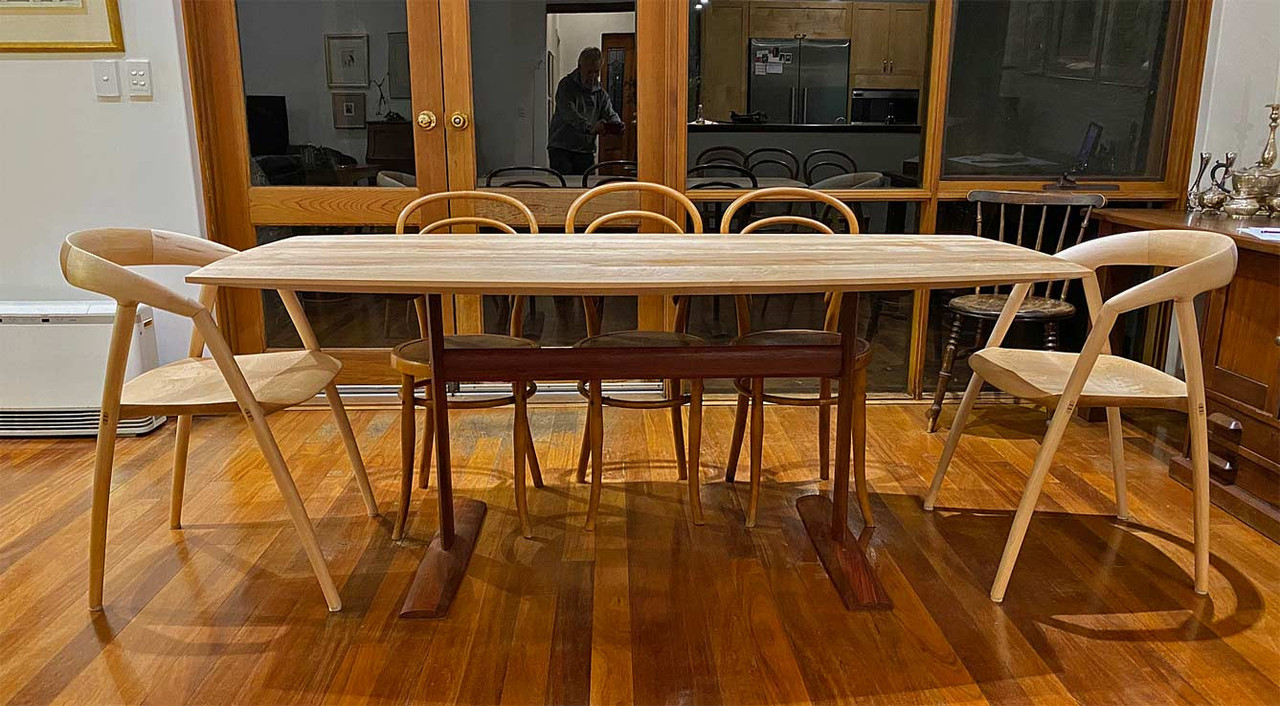
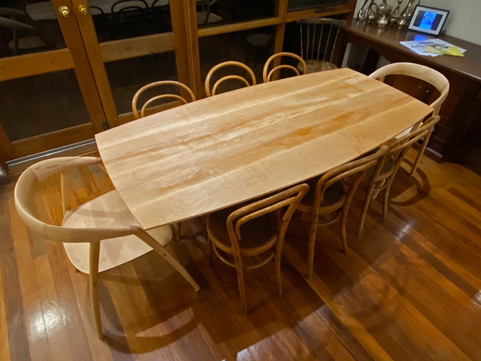
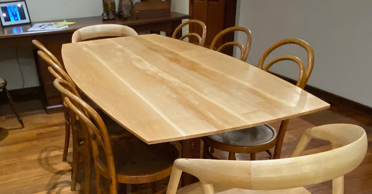
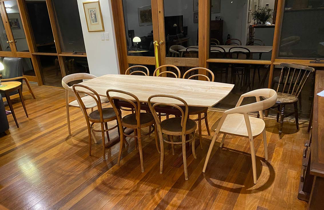
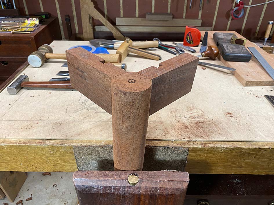
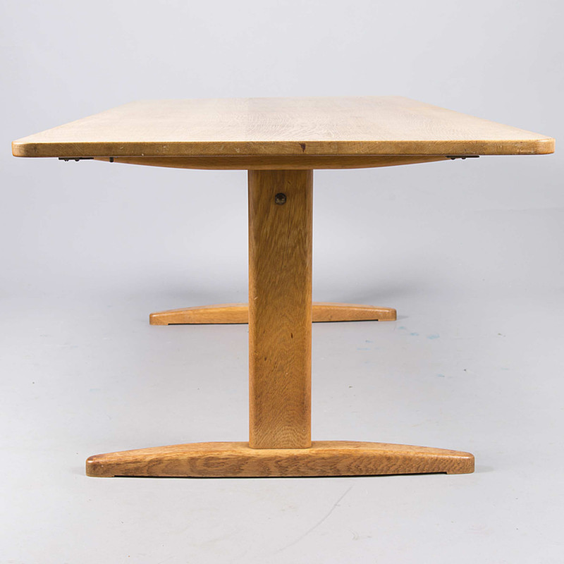
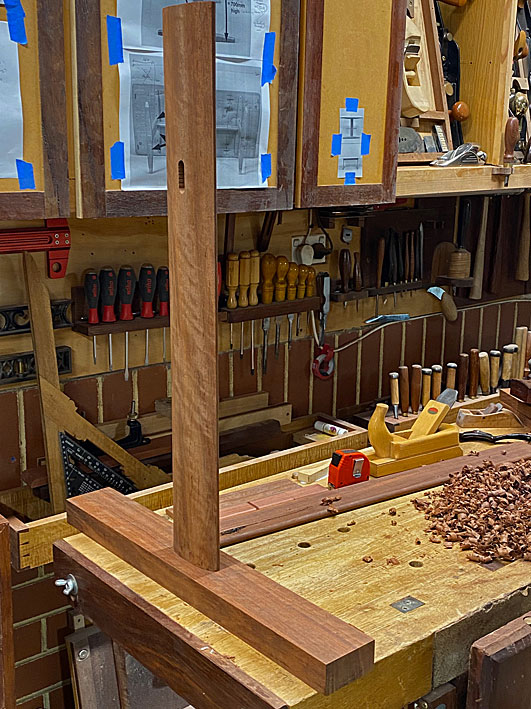
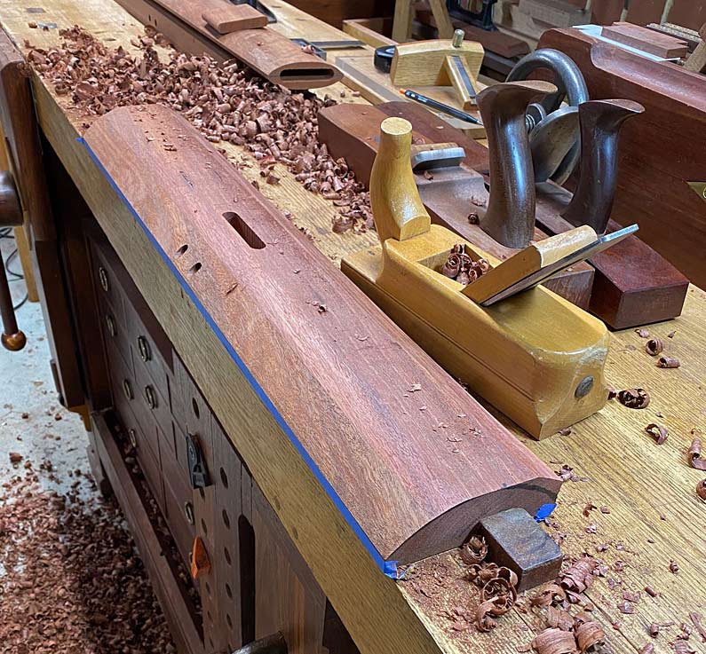
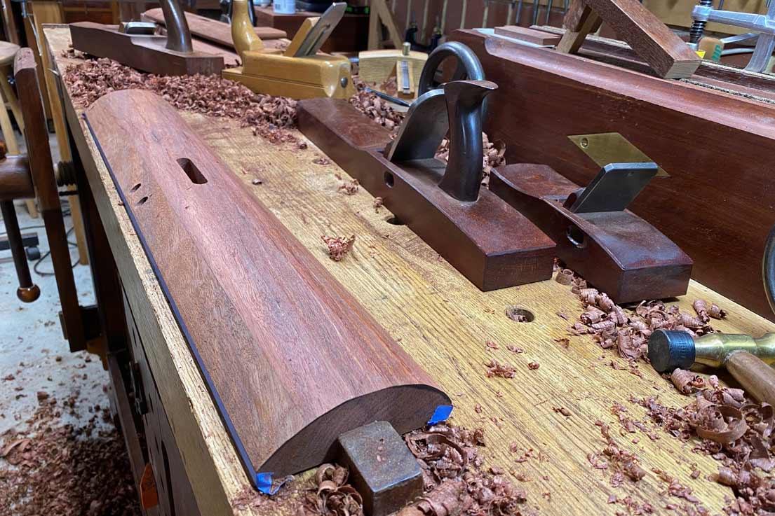
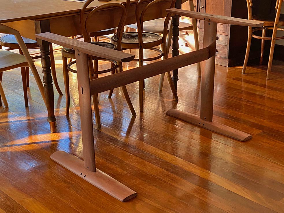
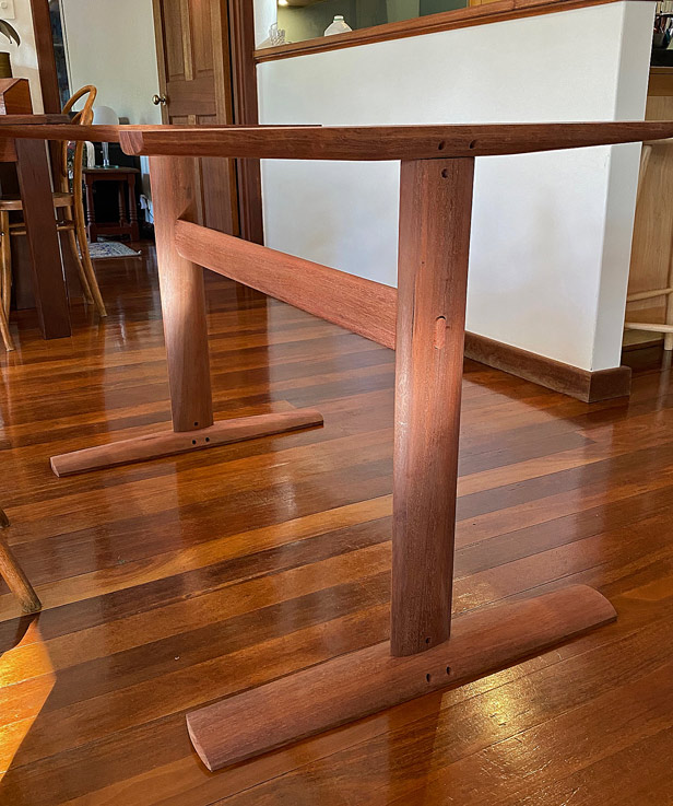
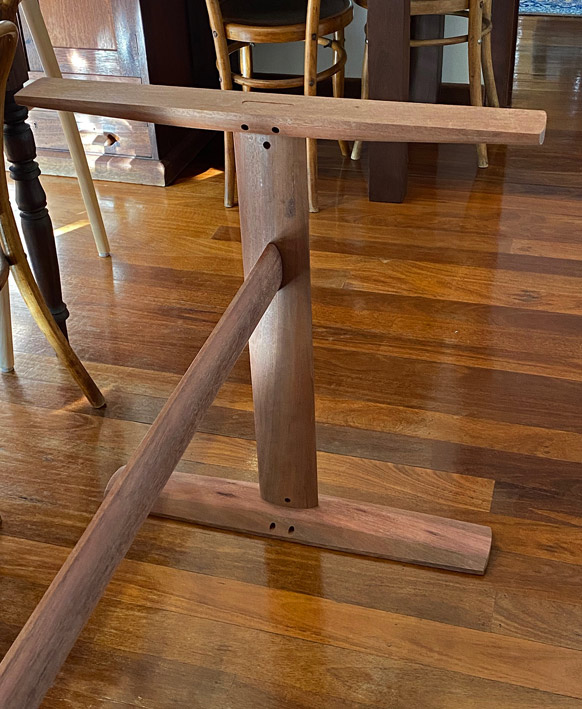
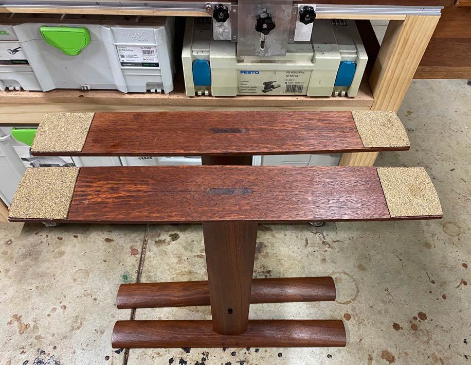
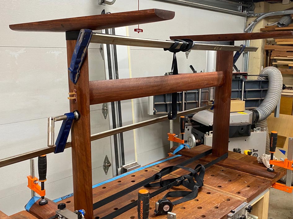
And here is the completed piece to judge the aesthetics of the sizing ...


Thoughts?

Regards from Perth

Derek
 
Love the construction, the rail does look pretty slim for the size of the table but I had a similar issue a few years back and it turned out ok.

Built this desk which has a 1300mm span between the legs and 60mm legs and 65mm rail, which slims down to 40mm to give thigh space. Rails are 25mm thick oak. Top is 22mm thick and buttoned on with buttons every 30cm ish.

The desk feels more sturdy than it looks and I can sit on the edge with no drama, I’m 100kg plus.


IMG_5009.jpeg


IMG_5010.jpeg


IMG_5011.jpeg
 
Time to re-visit the dining table, and move in a new direction. I have design, this time, a trestle table. The design is aimed at complimenting the (DC 09) chairs. To do this, in part the table legs must reduce clutter, which is the advantage of a trestle table ... the legs are tucked out of the way.

The base is to be Jarrah, which is a particularly hard and stiff wood. I have used in in many builds, as many are aware. One of the advantages this has given me is the option of building with thinner stock. All the trestle tables I have seen come with rather chunky legs and stretchers, and this is not the aesthetic I prefer.

I have made up some basic drawings and plans, but nothing I want to show here. Instead, I am posting photos of tables I found which have similarities - this is just to offer up some concepts to aid in visualising what I am planning. My design is different in important areas, but there are indeed similarities ...

Here is a table made by Borge-Morgensen, which has similar dimensions for the parts. The construction is very similar.


The top will be made from Rock Maple, and 1825mm long x 900mm wide, and 30mm thick.

At present my first choice is to use a shallow elliptical router bit, creating a pillowed (very slightly rounded) face to soften the edge. This is in keeping with the chairs, which are all curvy. The second choice - if this leaves the top looking too thick - is to use a shallow undercut chamfer. Note that the top will be curved along all sides.

Something like this Nakashima table ...


The legs link to the chairs through an oval shape I plan to give them (the legs of the chairs are oval) ... both in the horizontal and vertical parts. Joinery is pinned loose mortise-and-tenon and not the bridle joint in the Nakashima photo.

The light Rock Maple top will appear to float on the dark Jarrah base. That is the intention.

A comment about the DC 09 Chairs I built: When we were planning to build a larger table, it was necessary to add two more chairs. My initial thought was to find bentwood carvers to join the existing bent wood chairs, but we did not like their looks, and went searching for something else. Much of our furniture is contemporary, Mid Century-styled (as you may have noticed from my builds), and so I decided to add two modern carvers (we do not mind a mix-and-match), and use the table to blend all the pieces together.


Prep15.jpg


I managed to do a little work on the trestle table this weekend, in between watching the Olympic Games.

The mortise and tenon joinery is all loose tenons, which is easier to do accurately since all are through mortises. Plus I can orient the grain in the tenons for maximum strength (i.e. no run out).


With the exception of the cross support, all mortises are 1/2" x 70mm long x 40mm deep. The cross support mortises are 1/2" x 40mm long x 40mm deep.


The loose tenon stock is made simply and quickly: thickness quarter sawn Jarrah, saw to width, and round over with a 1/4 round bit in a trim router.


Regarding the choice of loose tenon joinery in this build: I have a preference for traditional mortise-and-tenon joinery. When I started making the chairs, this is what I did - integrated tenons from the seats. Then it became evident that they were vulnerable to breaking owing to run out. That is not a risk to take with chair legs. I started again, and this time used loose tenons, which allowed me to choose quarter-sawn stock.

The wedged M&T legs ...

12Completion_html_m68895486.jpg


... need to be echoed in the table. Hence the round ends (made with a router) in the table legs. Also the oval table legs linking to the oval chair legs.

Now we get to the interesting part. What I start with will be quite different from what ends up finished. There is very little that will not be carved away. Remember, the table is intended to blend with the two chairs I built. For this reason, the two vertical sections and the horizontal cross support will be oval in cross section. I have not seen this before ...


A template for later use ...


All the base parts cut to length and width, and mortised ...


A loose fit. There is just over 1m (40") between the trestle ends, with a 16" overhang planned. Note that the top support is wider than the base. Both will be carved away for an "organic" blend with the upright sections. It looks a little stick-like at present ...


Here is one leg or, rather, one upright. Everyone likes looking at shavings and planes. Start with a jack ... in this case a Stanley #605 with a radiused blade ... follow with a HNT Gordon Trying Plane to remove any tearout, and more shaping with smaller planes ...


Planing down to the marked curved lines ...


The tiny high angle BU smoother I made worked its magic ...


Here the vertical rests on an un-shaped base. That's where the challenge lies with shaping.


Still to be sanded and edges rounded ...


Regards from Perth

Derek
 
Last edited:
Quick review - we left off with then posts shaped into an ellipse ..


Time to turn that thick blocky base into a shapely, organic foot for the post.

It needs to be said that I binned the first feet I shaped as they ended up too thick looking. I want slim. I realised that a reason for this was that the blocky base was not wide enough (at 80mm), and so I built new ones, this time 110mm wide. In the photo below, the first is being shaped with a scrub plane into a half-ellipse to match the posts ...


This was followed up with a trying plane ...


Prior to shaping the base, it was drilled for the dowels which will later be used to draw-bore the mortise-and-tenon joint ...


The feet are too thick, and this will be reduced with a taper. Below the beginning and end is marked out ...


A succession of woodies are used (as was done in shaping the curves). First a scrub plane removed the bulk of the waste. This produces a rough finish ...


This is followed by a jack plane, which has a less aggressive radius to its blade ...


A trying plane now smooths out the surface ...


Finally, a smoother is used for the finish ...


It is relevant at this point to recall that the table top with be curved at the sides and ends, similar to this Nakashima ...


The ends are marked with a slight taper, about 8mm each side ...


This time I used a Stanley #604 with a close chipbreaker since it handles reversing grain best of all ...


The end curves were marked ..


... and the waste removed with a block plane.

This is combination after sanding to 400 grit ...


Hopefully, tomorrow may see the trestle table base completed.

Regards from Perth

Derek
 
The last two structural areas for the base were the central rail, which was also planed into an ellipse ...


... and the upper, support rails ...


These also required tapering, which I shall not go through again here. Instead, I will move to the completed - but dry and unfinished - trestle base. I would have preferred to have it all done, but the weekend came to an end. Rats.


These will provide some idea of the curves and, hopefully, organic feel I was aiming for ...


Regards from Perth

Derek
 
I have always found glueing up far more stressful than cutting the parts and planing them to fit precisely. My fear is always that something will move and the result will be a mis-match of parts. The additional concern is that the joinery may not be strong enough, and that my insistence on not over-designing joinery will prove that I am a hopeless amateur.

An important feature of the mortise-and-loose-tenon joinery is ensuring that the tenon does not move. Glue alone may suffice, but I have added 3/8" diameter pegs or dowels. Now I recently purchased a dowel maker on Temu for the grand sum of $19 AUD. How good could this be? Well, in short, it is pretty damn good, to my surprise.


But it would be the wrong way to make pegs/dowels for these joints. That jig make great dowels for filling holes, but for pegging tenons you need grain that does not have run out, is straight and strong. This means making pegs from rived stock. This was then pounded through a LN dowel plate ....


The peg holes had already been drilled in the base and upright, as shown previously. The loose tenons were glued into the bases and upper stretchers (but not the vertical stretcher yet). Now the holes were extended through the tenons ...


... the excess sawn off ...


... and the stubs sanded away ...


Sanding is the better choice here of using a chisel since the dust will fill any gaps in the pegged holes. Just add glue and sand flush.

Once the base and upper stretchers are complete, the vertical stretcher can be glued and clamped, first to the base ...


... and then the upper stretcher is added ...


While clamping all together, the level is checked to be parallel. This was found to be within 0.05 degree. Happy with this.

The loose tenons for the cross stretcher are sawn for wedges ...


The tenon is shaped for later ...


The wedges are sawn roughly to shape, and then planed to match each other using a simple fixture made for the purpose ...


Before the cross stretcher is glued, the underside of the bases are given protective pads (made from Crubber). These raise the ends about 2mm, ensuring both stability on the floor as well as a non-slip ...


Finally, the cross stretchers are added and the ends clamped together ...


Attention and time was given to ensuring all was perfectly square, and remained so once clamped up ...


The first coat of Whittle Evolution hard wax oil (Classic) was rubbed on. A second coat was added a day later. The colours in this Jarrah just popped out ...


Returning to the design of this trestle table base, the aim was to build something to meld with the DC 09 chairs I built. How have we done? Keep in mind that the table top will be Rock Maple.


The elliptical sections of the trestle base hopefully match the legs and arms of the chairs ...


Lastly, with regard the strength and stability of the slim sections in mind, I tested this by pressing very heavily on the ends of the upper rails. They did not budge [smile]

Regards from Perth

Derek
Fantastic work as always. Just one design comment if you don’t mind. I think the foot still looks too heavy. It would benifit from more tapering on the edges toward the ends so the ends of the feet look narrower. Not sure I explained that too well. The backs of the carvers taper more aggressively and it would be nice if the feet did the same.
All my own opinion of course.
 
Paul, I chose not to remove any more from the edges as they would be vulnerable to damage if a shoe bumped into or brushed them.

Also, it's about proportions - the more one thins out the edge, the more the central area looks thicker. I ended with the balance I preferred.

Regards from Perth

Derek
 
Paul, I chose not to remove any more from the edges as they would be vulnerable to damage if a shoe bumped into or brushed them.

Also, it's about proportions - the more one thins out the edge, the more the central area looks thicker. I ended with the balance I preferred.

Regards from Perth

Derek
Derek,

Good design considerations. I assumed you had thought it through. Your attention to detail is always first class.

Paul
 
Time to begin the table top. This will end up 1840mm long and 900mm wide, with curved sides.


Whoever thought that using machines saved all the grunt work clearly has never built a large table top that started with 2" thick x 10" wide x 6 1/2 feet of Rock Maple! Carrying this around on my own - there is no such thing as "flipping a board" - was a serious workout. Who needs the gym?

One board was just over 12" wide and needed to be cut down to 10". This is too long - and at this stage too heavy - for my slider, and so the ancient track saw came out. Minor issue was the track is short (1400mm) ...


No problem. Just move it down ...


The MFT also works as an in- or outfeed for the jointer and slider ...


The first two boards I jointed I did in the traditional manner, that is with the hollow side facing down ...


This was a slow and physically exhausting process in spite of the blades set for a deep cut. For the second two boards I flipped them over and ran then over the concave using the fence to balance it on its centre. This was fast! At least twice the speed of hollow-down.

With one jointed side and edge, the boards now needed to be re-sawn to 35mm. The plan was to leave them a little oversize to acclimatise and then thickness to 30mm.

The bandsaw is a Hammer N4400, which is an 18" with a 4 hp motor. Plenty of grunt to drive a 1" carbide Lenox CT Woodmaster blade. But .. running a 1900mm long board on the table is another kettle of fish.

I brought in the drill press table as an infeed, and piled some heavy boards on the slider outfeed as an outfeed ...


The drill press fence made a great guide ...


And the re-saw was as good as I could hope for ...


Four boards jointed and thickness planed both sides ...


And finally ripped to width ..


Now we can play at selecting the boards for the top ... try ... flip .. turn ... flip again ... and in the end ...


While the boards came off the jointer and slider fairly straight, they needed to be made perfectly straight and square for a gapless joint. This takes place at the bench with a jointer plane ...


What I do is place two adjacent boards together ...


... and shine a light at the rear ...


... to show where the gaps are ...


Remove the high spots.

Next, check the edge for square. This one is angles slightly to the right ..


The strategy now id to move the plane over until only the right side of the blade is cutting. You can see the far side line disappearing ...


This is the half shaving produced ...


Now that the edge is square, follow this by planing until a full shaving is obtained ...


Finish with a fine shaving ...


Incidentally, the jointer used here is the Veritas LA Jack. I also have a Veritas Custom #7. Both are excellent. Both get used equally.

The aim is to plane a spring joint - a very fine hollow - at the centre of each board. This will create a gap of around 0.5mm, which can be pulled together with clamp, and serves to avoid the ends of the boards opening up ...


All done, and the next step is to add biscuits to aid in aligning the boards. This is unnecessary for short lengths, but here it aligns the newly jointed tops ...


In preparation, the top of the MFT is covered in plastic film ...


Glue rolled on ...


Two board at a time initially ..


And later joined together ...


This is where we are at. Back to it next weekend.

Regards from Perth

Derek
 
As always Derek, fantastic work and huge admiration for your skills and effort in doing this!
Hefting large and heavy timbers single handed through bandsaws and planers was something I used to on occasion do without a care in the world, despite the weight and physical effort involved, but alas now I am unable to manage anything on that scale - kudos!
 
Resawing flatsawn stock sometimes results in cupping. It will be interesting to see
how your table top fares in the coming weeks.
Hopefully, all will be well.
 
How do you find the tct bandsaw blade Derek?
I’ve been considering one but find that the M42 blades I’m currently using are prone to breaking at the weld before they’re blunt, leaving a mangled un-repairable blade.
 
Max, the Lenox Woodmaster carbide blade is thicker than standard blades and is vulnerable to breaking (cracking) on smaller diameter wheels. I would say the minimum size is 16". My Hammer N4400 is 18". These blade are amazing in that they can last a long time. This one is used a lot, and in very hard Aussie woods, and has so far gone about 4 years. Still sharp.

Regards from Perth

Derek
 
This is a large post, with many photos, and it takes up to the conclusion of this build. There have been many small details in the design and execution which, when added together, create the final piece. My wife just loves it, and I'm quite pleased myself, so I am happy to share the details for those who are interested in building something similar and with the techniques I used.

With the top glued up, the next step was to mark the outline, which was done by making templates ...


Block plane making shavings of 6mm MDF ...


One quarter used four times ...


Marked out with blue tape for visibility ...


No, I cannot lug this over to the bandsaw. I am not that strong. A jigsaw is used, like a regular person does, cutting close to the line ...


The templates then are used for pattern routing ...


The end grain is smoothed with a block plane. The question is, which works better, a skew block plane or a straight-bladed block plane. Answer: they do the same as one simply holds the straight-bladed plane at an angle :)


The top is pretty flat. The use of biscuits to level the joints worked well. Now the surface is planed with a smoother. This is the finished surface. No sanding was done ...


The side edge is 30mm thick. The plan is to chamfer the edges leaving a 10mm face. This is marked in blue tape ...


The base is positioned on the underside to determine how far in the chamfer will be made ...


A nice, even if rather old, Festool power planer takes away most of the waste in no time at all ...


This is finished to the lines with hand planes ...


The tow ends of the underside are given a long taper, first using the power planer to remove most of the waste ...


.. and then finished with a LA Jack ...


Top done. Time to attach the top to the base.


The plan here is to use bolts into metal inserts, as I do not like the idea of inserting wood screws which might cause splitting and also be vulnerable to being pulled out.


A pilot hole is drilled through the base into the table top to position the bolt holes and inserts.

The holes in the base are made with a 3/4" forstner bit, then drilled for the 6mm bolts using a 7mm twist bit (for a little wiggle room). The hole closest to the leg is fixed while the other two are elongated 2mm each side of the hole for expansion.


Note that the bolt holes go through the base, rather than using wooden buttons as the holes essentially make the attachment invisible from the sides ...


With all attached, the table is done! And two coats of Whittle hard wax oil are rubbed on.

So are we all ready for the unveiling? Drum role ...


The aim of the design was to unite the table with two DC 09 chairs I built. In common are elliptical sections in the table and chairs. The other chairs are vintage bentwood, and the use of curves allows them to be included. The reason for a trestle table, rather than a traditional four-legged table, was to reduce the number of legs with different angles. This is aided by using dark Jarrah for the base, as the base disappears and the Rock Maple top is left as a line connecting the DC 09 chairs.


The curves of the top ...


And a final picture from the kitchen area ...


Thanks all for following along with this adventure.

Regards from Perth

Derek
 
Back
Top