Coffee table for a nephew

UKworkshop.co.uk

Help Support UKworkshop.co.uk:

This site may earn a commission from merchant affiliate links, including eBay, Amazon, and others.

Derek Cohen (Perth Oz)

Established Member
Joined
2 Mar 2005
Messages
3,391
Reaction score
1,890
Location
Perth, Australia
This is a blended build - both power and hand tools. I tend to post to this forum, so here we are ...

My nephew is getting married in February, and I offered to make a piece of furniture as a gift. The offer was open-ended, and the couple decided they wanted a coffee table. Their taste runs to mid century Danish, and so I sent them a bunch of example from the Internet to get the ball rolling. They fell in love with the following design ...
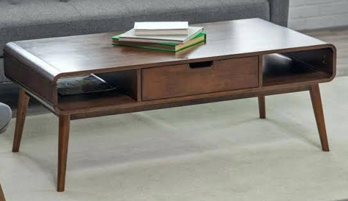
Davids-table1.jpg


There shall be a few interesting challenges along the way since I am using solid wood and, I imagine, the "model" is built of veneered ply.

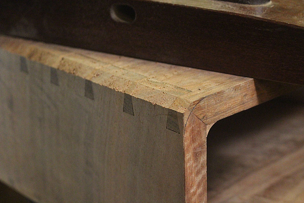
The joinery will be rounded corners shaped from through dovetails, mitred at each side. The challenge is to have accurately cut and fitted dovetails in hard Jarrah (no compression) as the outside will be removed in the rounding process.

The other challenge is the splayed and angled legs which, for added strength, will be fitted to a traditional rail design, that is, the legs and stretchers will be mortice-and-tenon joinery. The legs will splay from the corners.

Lastly, the drawer will extend the full width, and be opened from either end. No handles.

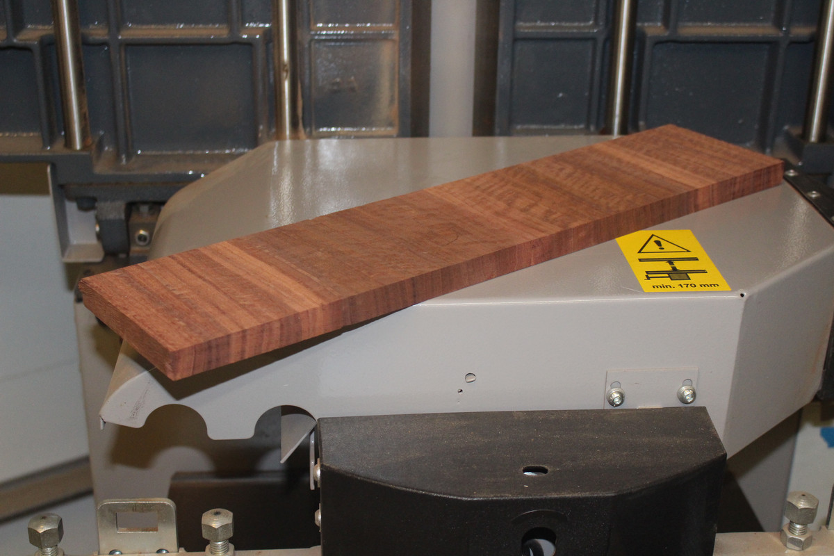
Beginning the prep by resawing some really nice Fiddleback Jarrah, which will be the top and sides. The length of the coffee table is 1000mm ...
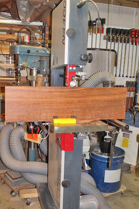
1a.jpg


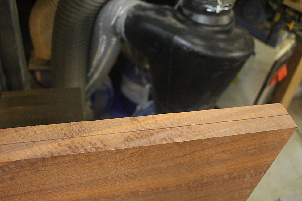
I was watching the boards come out of the blade, keeping an eye on the kerf for movement. This even kerf told me that the boards were going to be well-mannered and stable ...
2ax.jpg


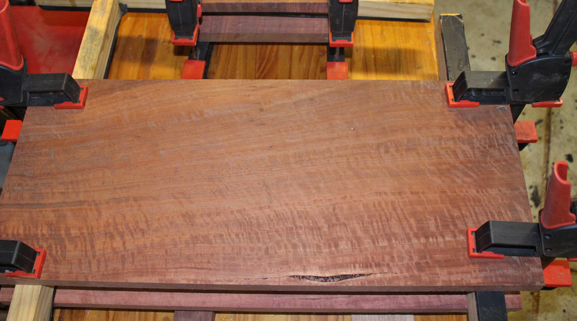
Here's an example of the figure. These boards will be bookmatched to create a width of 500mm ...
4a.jpg


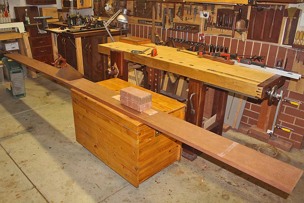
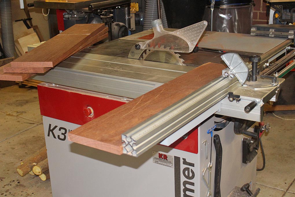
The lower side of the coffee table will be made of more "common" narrower Jarrah boards (still extremely nice!). I picked up a length 4m long, and then joined three together to get the width ...
5a.jpg


7a.jpg


The boards were stickered for a week ..
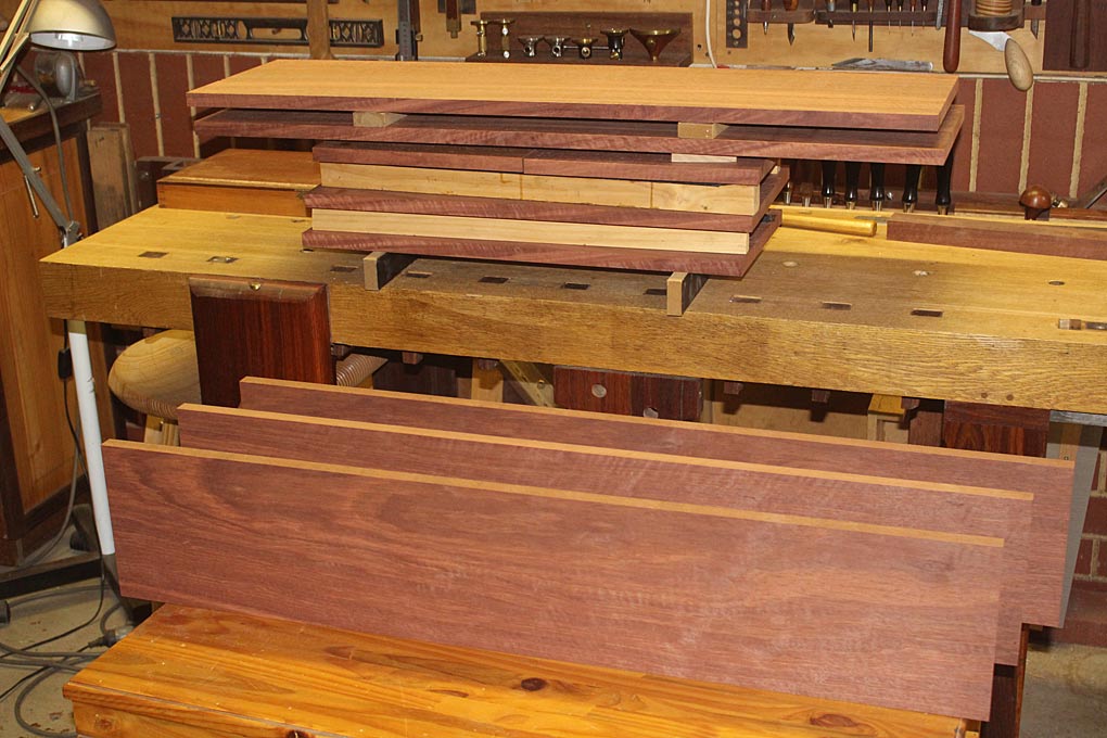
8a.jpg


Some may have liked to have accentuated the centre figure this way when book-matching ...
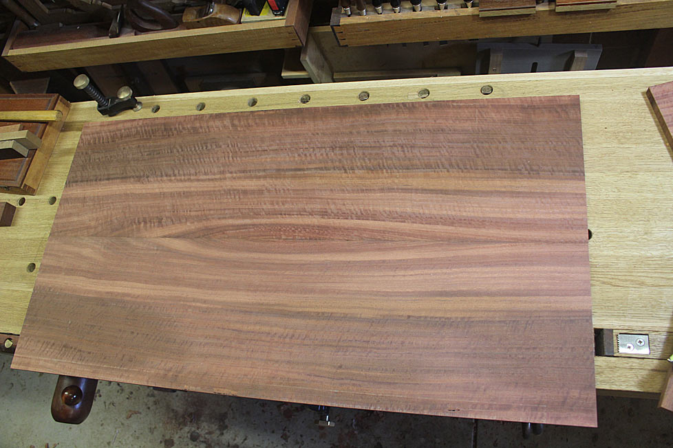
9ax.jpg


Too busy for my liking.

I preferred this ...
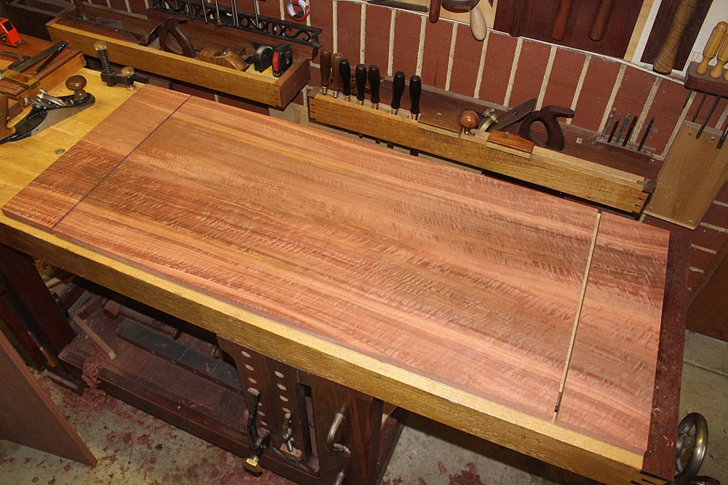
16a.jpg


And this is where I left the boards at the end of last weekend ...
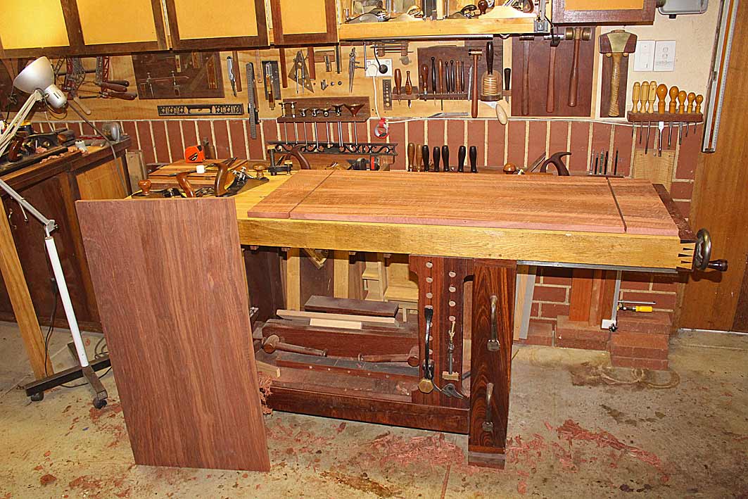
15a.jpg


Regards from Perth

Derek
 
Excellent! I love the way you swerve into the difficulties of using hard, tool-resistant but beautiful jarrah,and including some challenging curves in the design. I'm sure your confidence will be totally justified.
 
The immediate challenge is to create the curved ends. The plan is to make dovetailed corners, round them on the outside and add a filler/filet to the inside corner, which will be hollowed to compliment the outer radius.

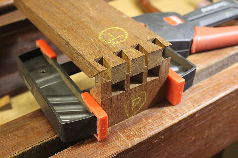
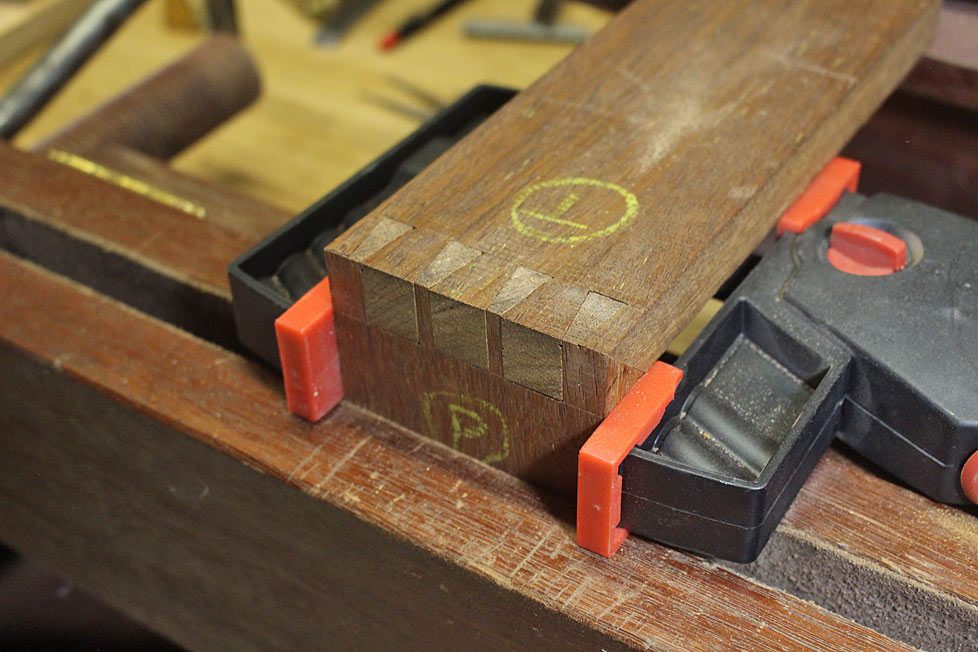
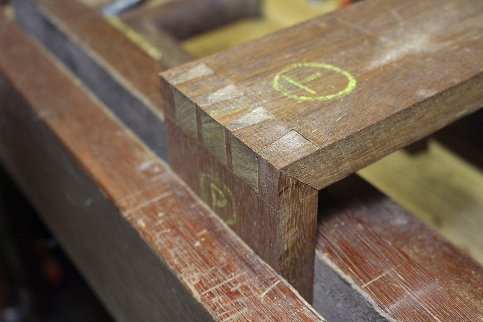
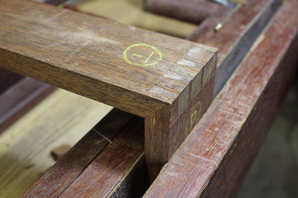
Complicating this is the need to mitre the insides of the dovetailed ends, since this will permit the shape to flow better than butt ends. Interesting ... as I have never made mitred dovetails to date. This is going to be a steep but quick learning curve!

I spent some time researching mitred dovetails. There is not much around. The only book I could find with directions was Ian Kirby's "The Complete Dovetail". I like Ian's work, but the writing here were not his best. There is a short video by Chris Schwarz (Google for it), which was helpful. There was also an article on the UKWorkshop forum (by Custard), which is a Pins-first method (I tend to saw Tails-first). There were one or two other articles to be found, of less assistance to someone like yours truly, who becomes easily spatially challenged. In the end I worked it out but, reflecting on the method that evolved, it does not look like those who came before. Perhaps it is a different way of doing it? I really do not know. Let me have your thoughts here. Anyway, I plan to show it for the education of those who want to learn a method.

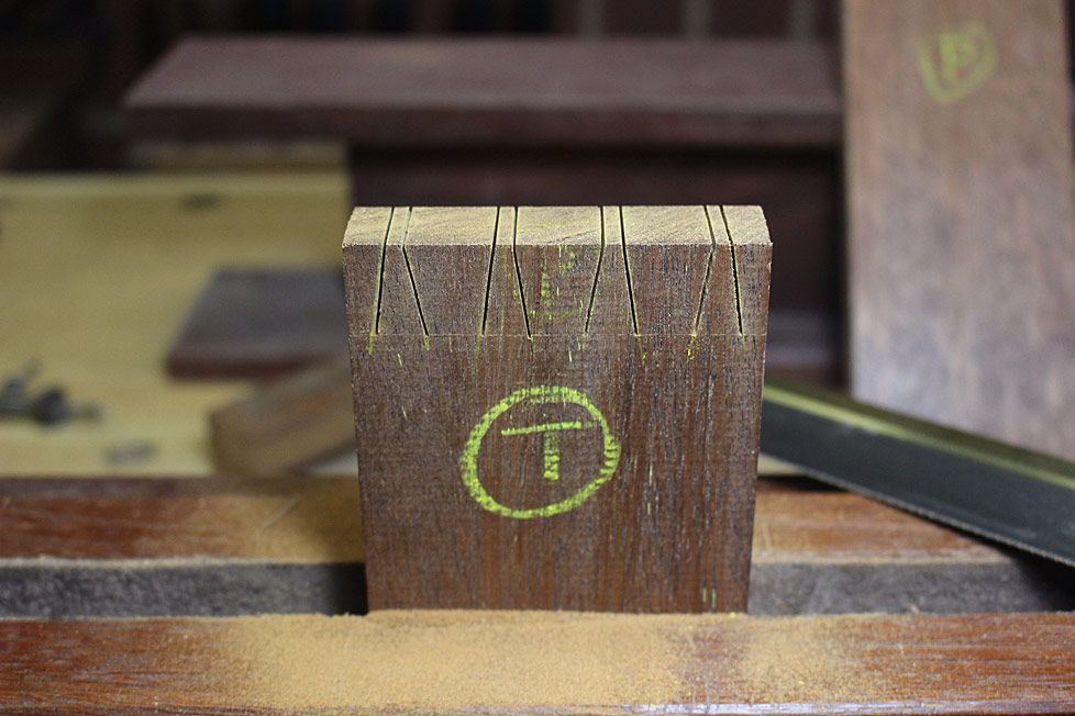
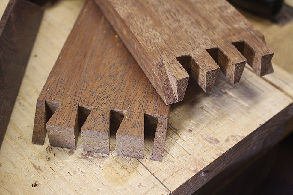
Beginning with a tail board that has been marked and sawn (to speed up the description). Note that there is no shoulder here (which is common on butt ended dovetails). The wood is Merbau, which is hard, hard, hard. 20mm thick, as per the panels on the table ...

1a.jpg


The aim is to saw all the tails. Forget about the mitre for now (... this is a departure from the methods I observed).

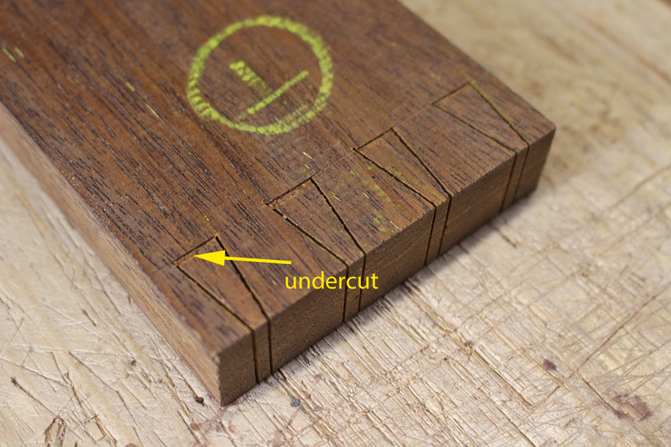
To make the removal of waste easiest, undercut the baselines (shallow cuts to avoid losing vertical) ...

2a.jpg


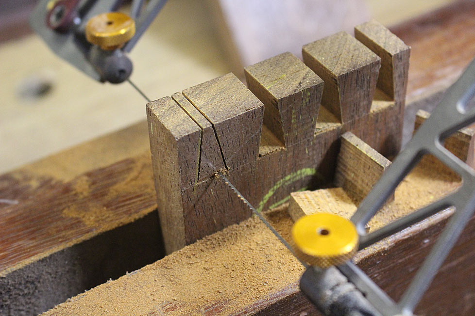
Now fretsaw away the waste. Get as close to the baseline as you dare! My cuts are about 1mm ...

3a.jpg


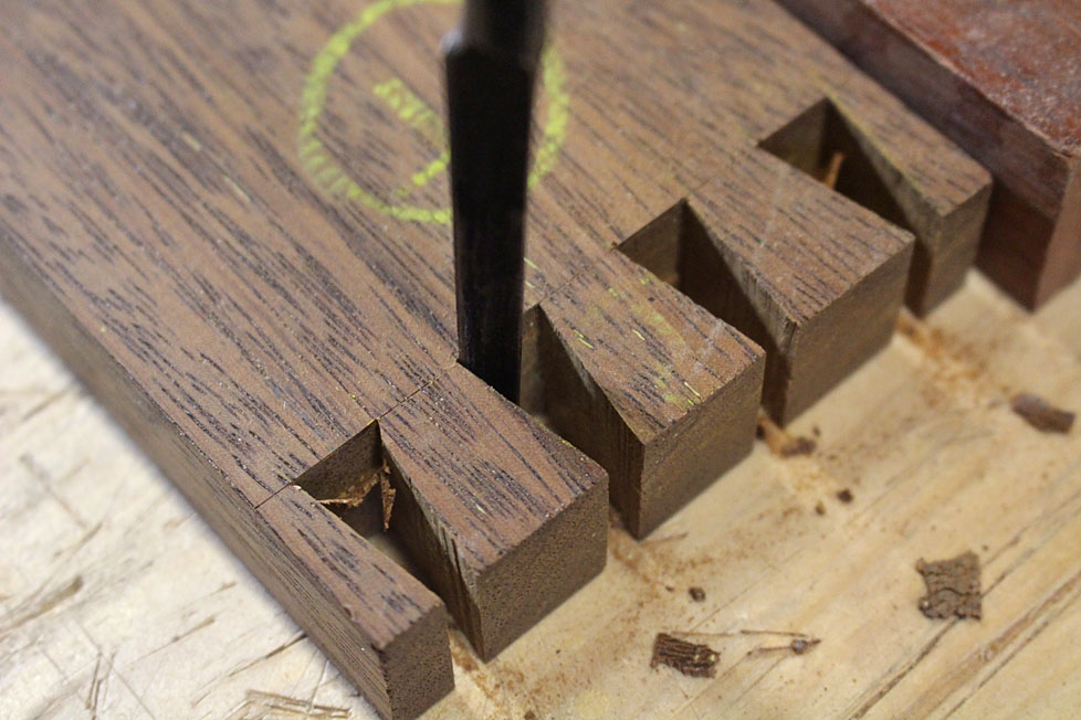
This enables the minimum of waste removal. You can place the chisel immediately against the chisel wall and pare/chop down halfway ...

4a.jpg


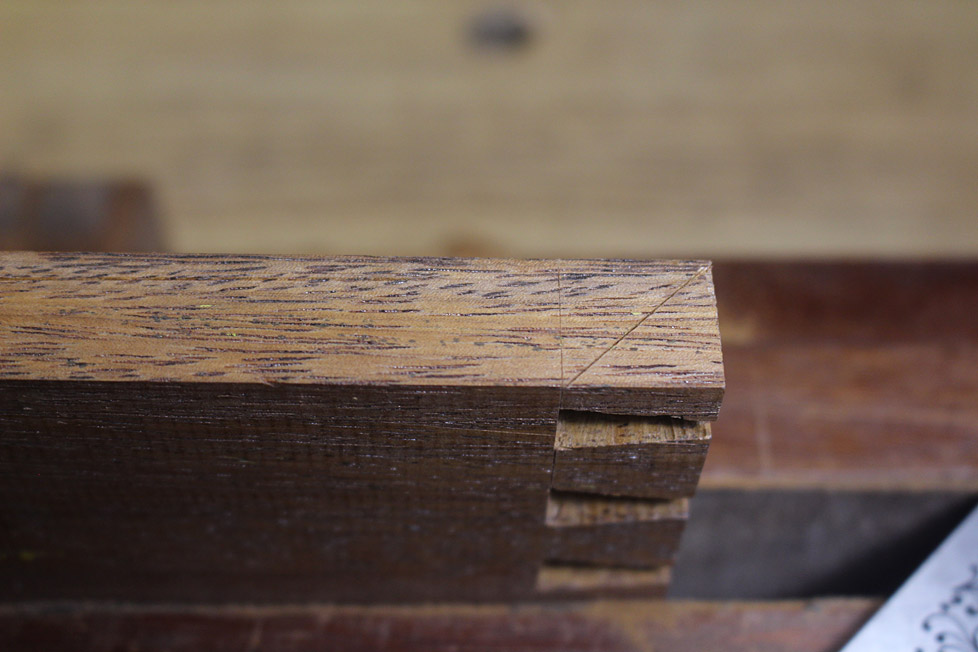
With the waste removed, mark the mitre cuts at the sides - but do not cut them yet (this is another departure) ...

5a.jpg


6a.jpg


Time now to transfer the marks to the pin board.

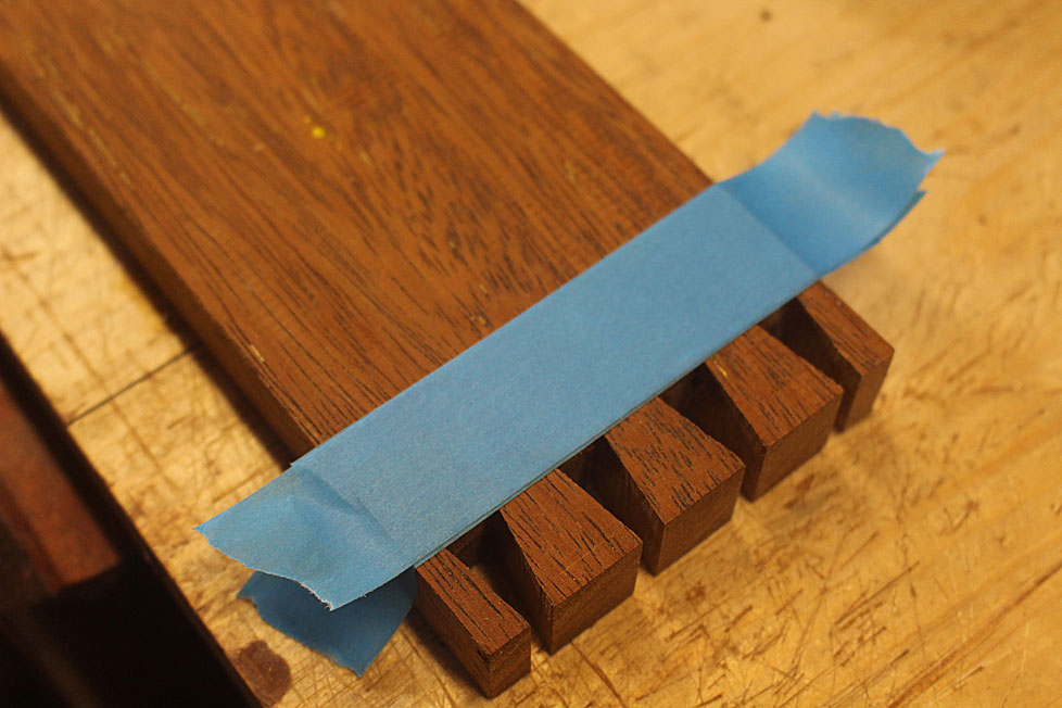
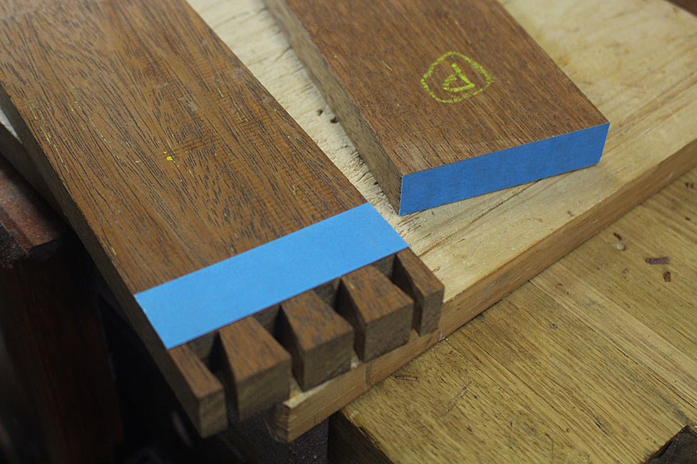
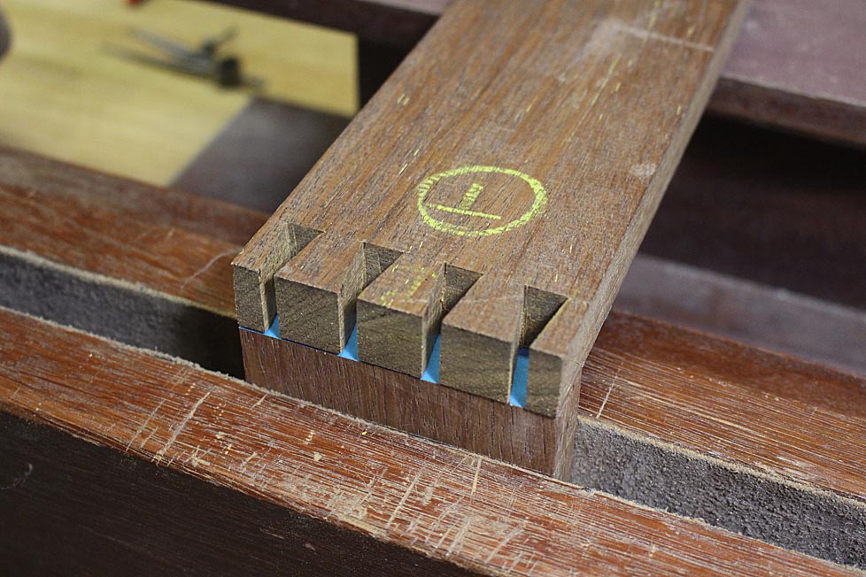
First, here is an alternative to the "#140 trick" (the #140 trick involves creating a shallow rebate to securely connect the tail board to the pin board when transferring marks. This was popularised by Rob Cosman and Chris Schwarz, amongst others). My alternative is three layers of blue tape, which is peeled away afterwards.

Lay three layers of blue tape over the baseline. No need to be careful ...

7a.jpg


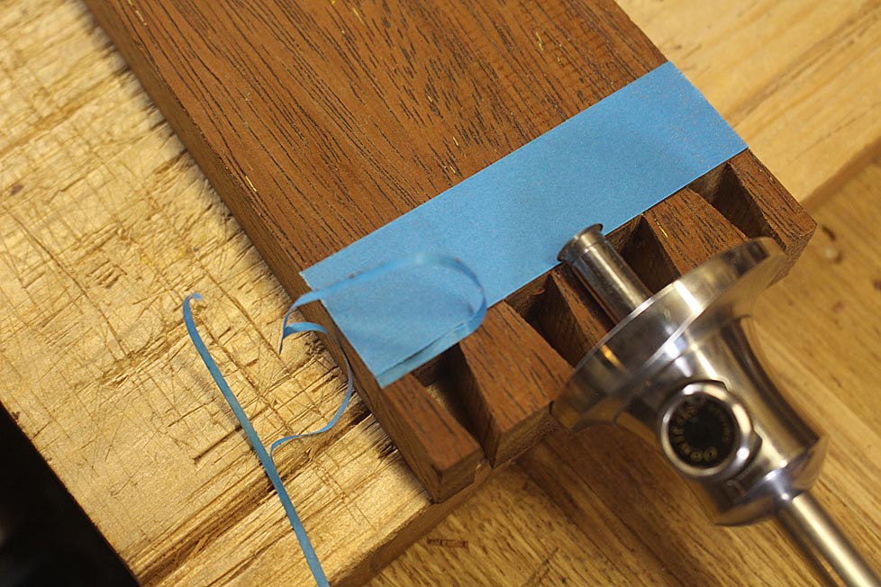
Now use the cutting gauge (which marked the tails) to slice away the tape, leaving an edge butting against the baseline ...

8a.jpg


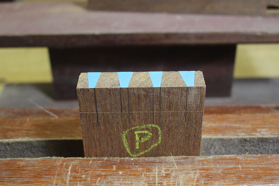
This is the fence. Here it is seen with the pin board, which has a layer of blue tape on the end ...

9a.jpg


The "fence" makes it easy to align the boards, while the blue tape on the pin board also acts as a non-slip ..

10a.jpg


When you trace the sockets (with a knife), the outlines look like this (great for old eyes!) ...

11a.jpg


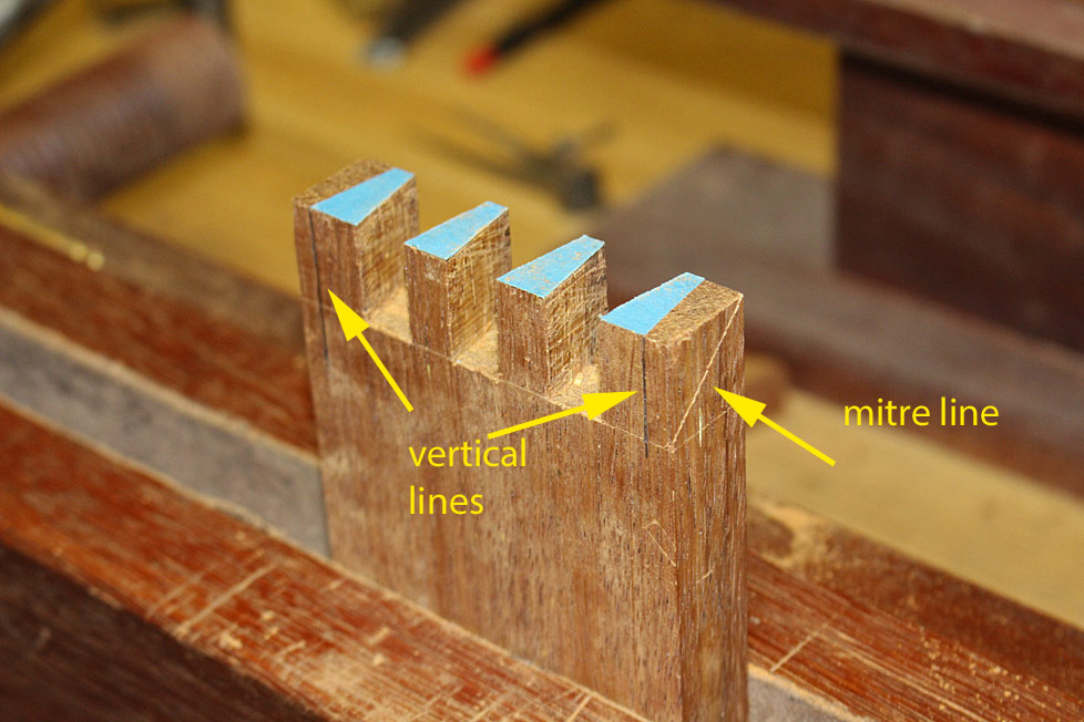
Drop all the vertical lines, with the exception of the line on the outside at each side ...

11a.jpg


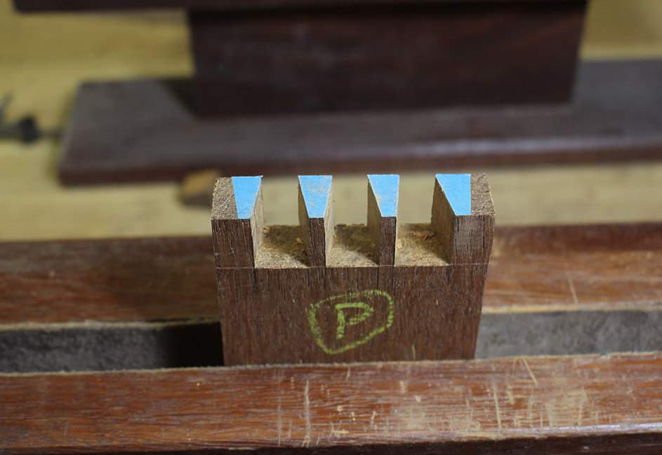
Remove the waste in the same way as done on the tail board (undercut the baseline, fretsaw and chisel) ...

12a.jpg


Mark out the mitre lines ...

13a.jpg


... and drop the verticals on the reverse side...

14a.jpg


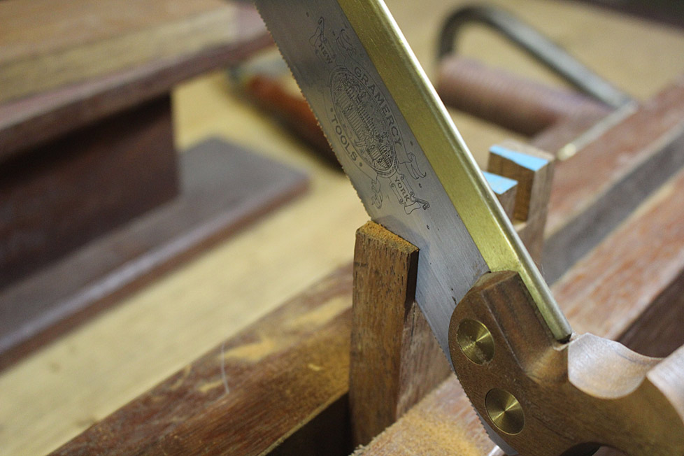
Now saw the mitre cuts and remove the waste ...

15a.jpg


16a.jpg


Do this on the tail board as well - the reason it was left until now was that it would be difficult to transfer the outside tail if the mitre was sawn.

Stay about 1mm from the mitre line. Do not saw to the line. This will be more accurately shaped with a chisel.

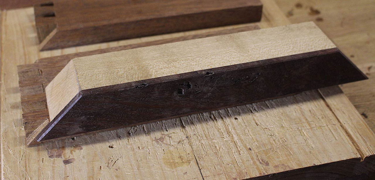
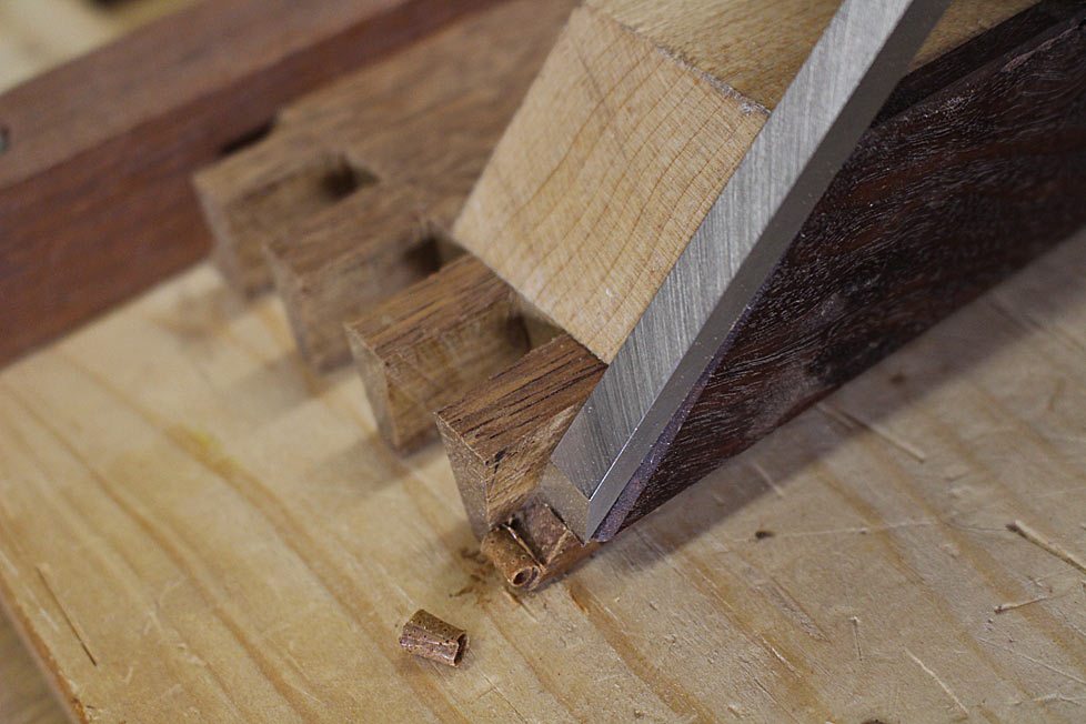
For chiseling, use a mitre guide. This is just a 45 degree saw cut. I made a double-ended guide - to use on opposing sides ..

17a.jpg


18a.jpg


Take it slowly, a smidgeon at a time.

19a.jpg


Finally ... the moment of truth arrives ... will she .. won't she ??

20a.jpg


Looking promising as the top is pressed together with finger pressure. Then I wack it - the wood is uncompromising. The clamp is to prevent any cracking in such circumstances.

21a.jpg


Not too shabby.

Mitres are tight ...

22a.jpg


23a.jpg


Now about the rounded edge ... here is the secret weapon:

23-1a.jpg


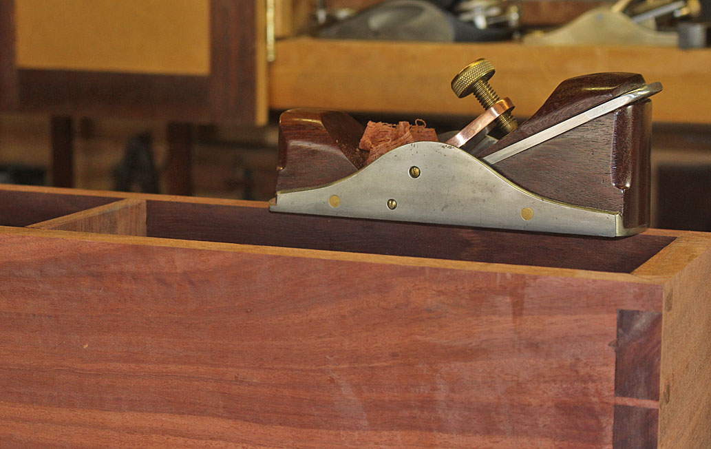
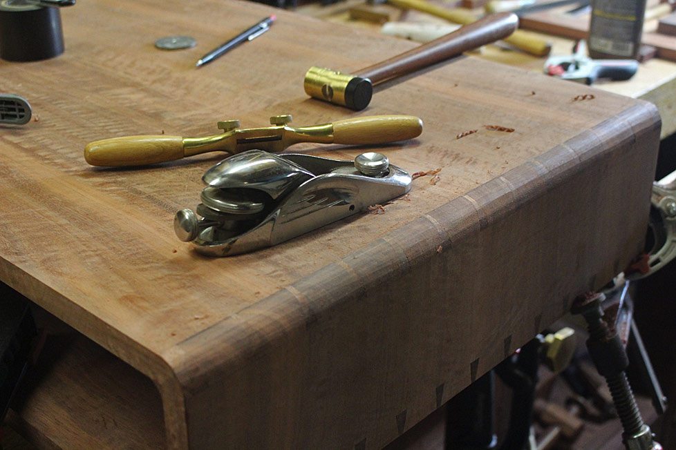
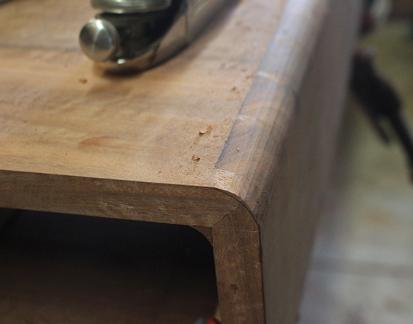
After marking out, the waste is removed with a block plane, and then sanded smooth. Just lacking the inner filet ...

24a.jpg


25a.jpg


Enough practice. Now for the real thing. A bit more of a challenge as the panels are 500mm wide.

Regards from Perth

Derek
 
Off we go on another wonderful piece of design, good quality workmanship and superb presentation. I really enjoy Derek's posts. Something to look forward to and so educational.
 
A few progress shots.

The main focus is to complete the carcase. However, to do the carcase, it is important to plan ahead for the drawer case.

The drawer case (at 10mm) is half the thickness of the carcase (20mm). The (eventual) drawer fronts (one for each side) will be the same Fiddleback Jarrah as the top and sides, and will be inset (rather than lipped). The purpose of the thinner sides is simply aesthetic - I want it to look lighter, to subtly separate it from the carcase. The drawer front will be the same thickness as the carcase, and the drawer sides the same thickness as the drawer case.

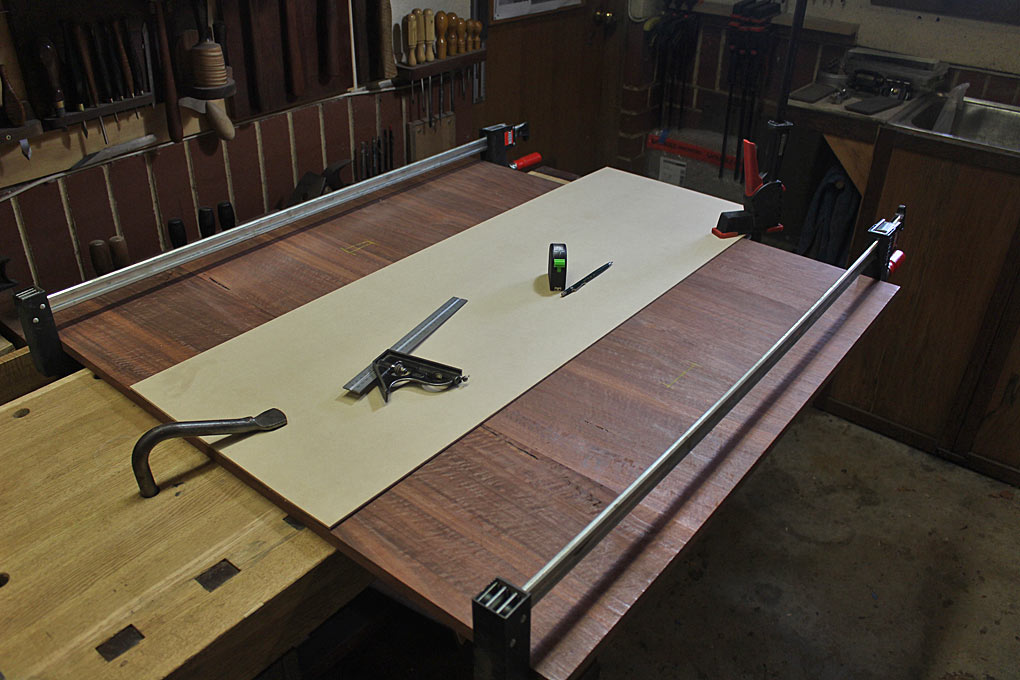
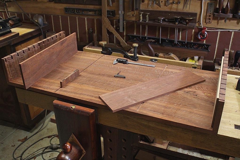
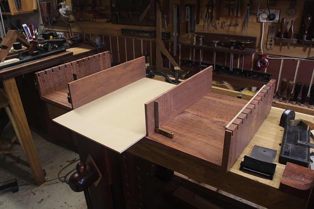
Before beginning on dovetailing the ends, stopped dados were marked out for the drawer case. The lower- and upper panels were clamped together and a MDF template of the drawer case set in position...

Aa.jpg


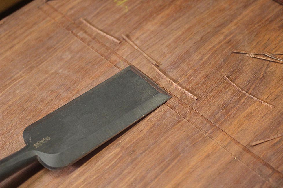
Marked out, chisel walls made ...

Da.jpg


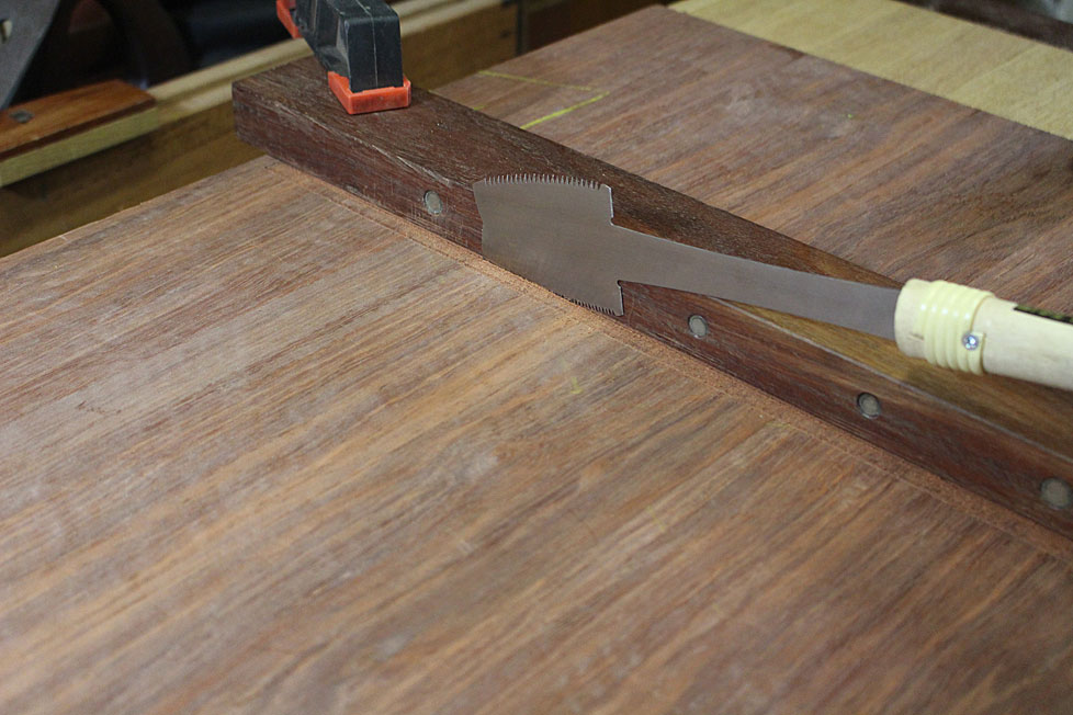
... to guide the saw cut ...

Ea.jpg


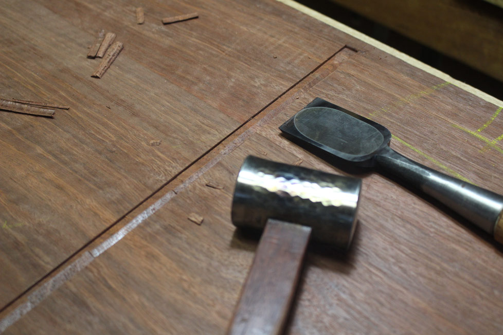
Then chiseled ..

Ga.jpg


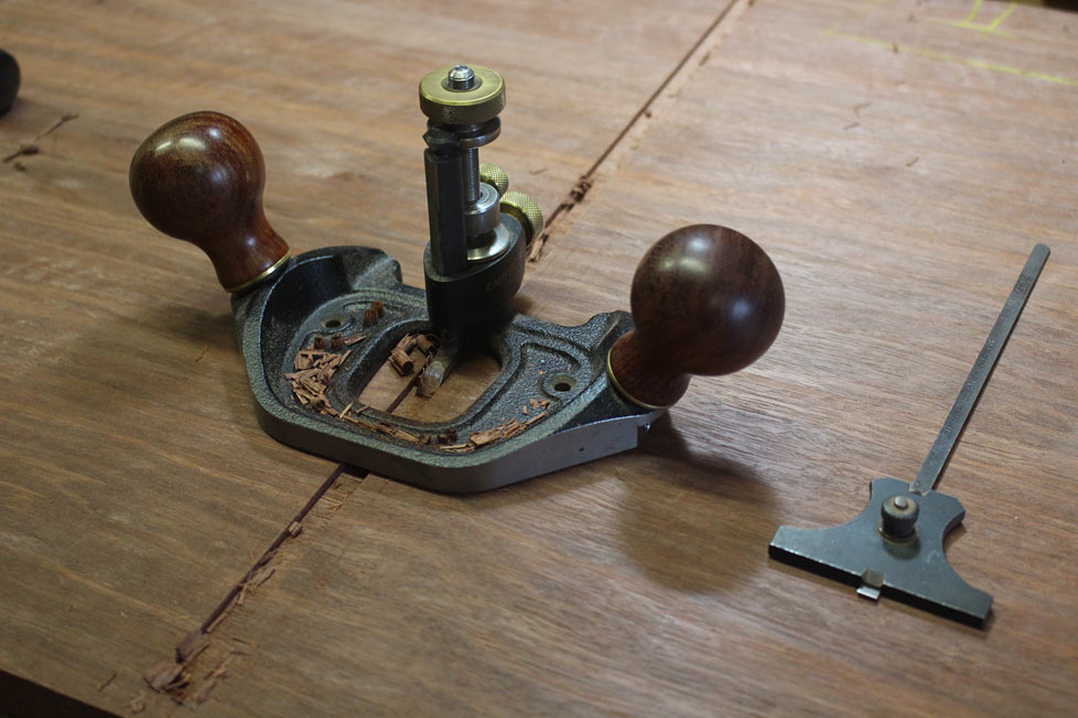
... and routered out ...

Ha.jpg


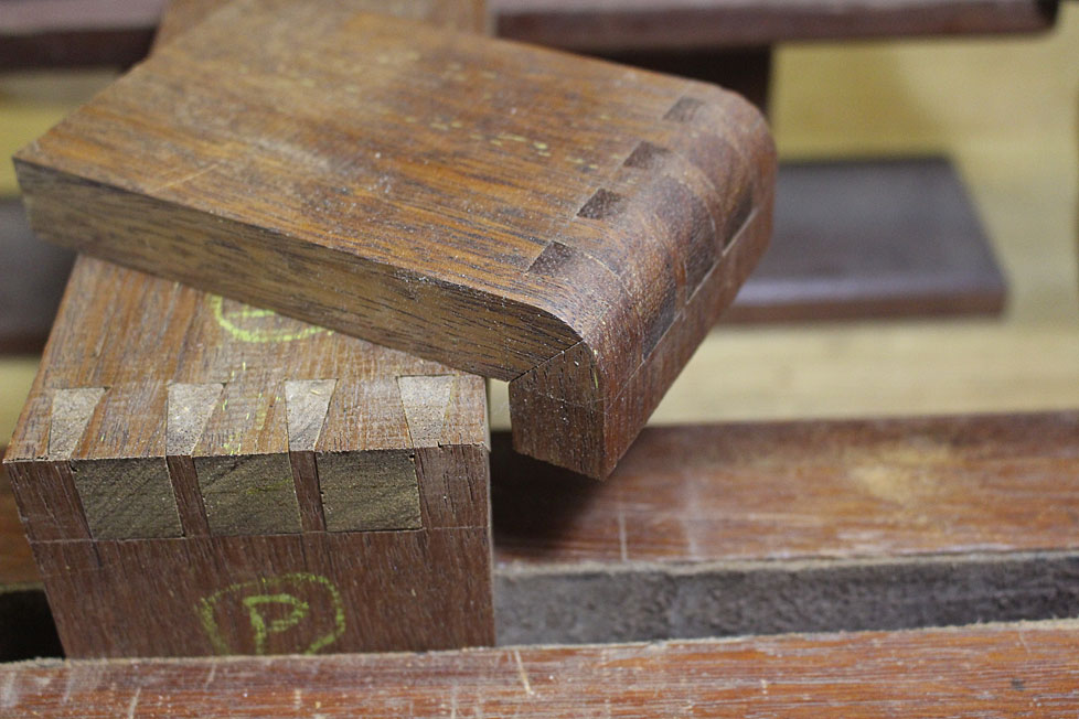
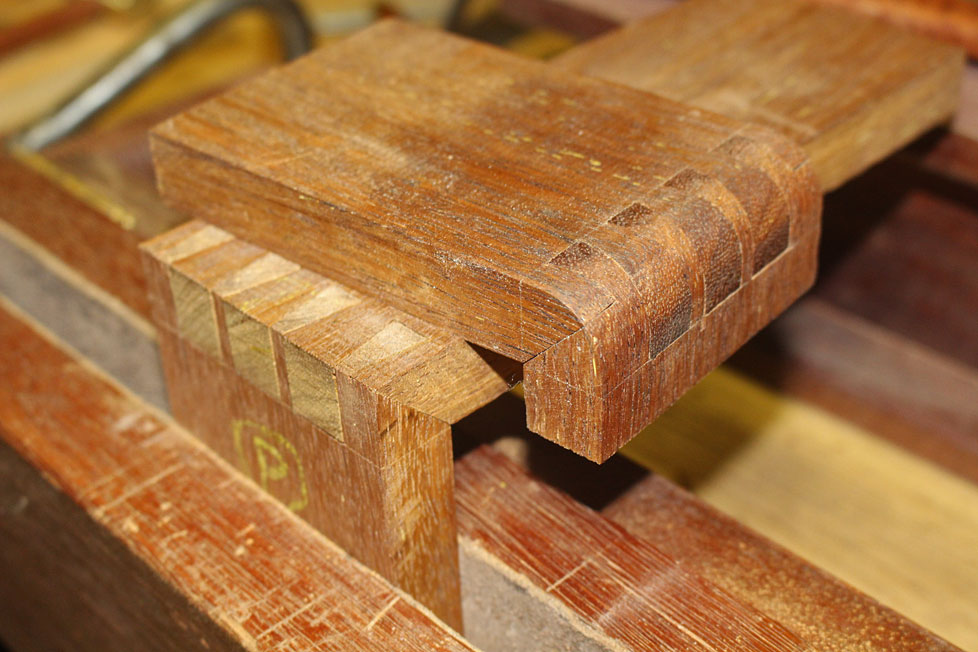
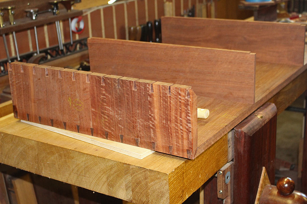
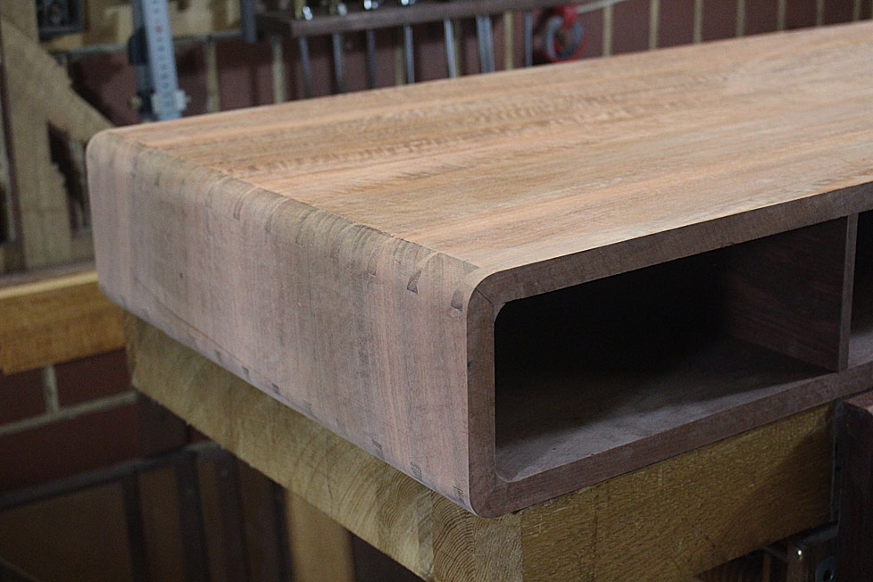
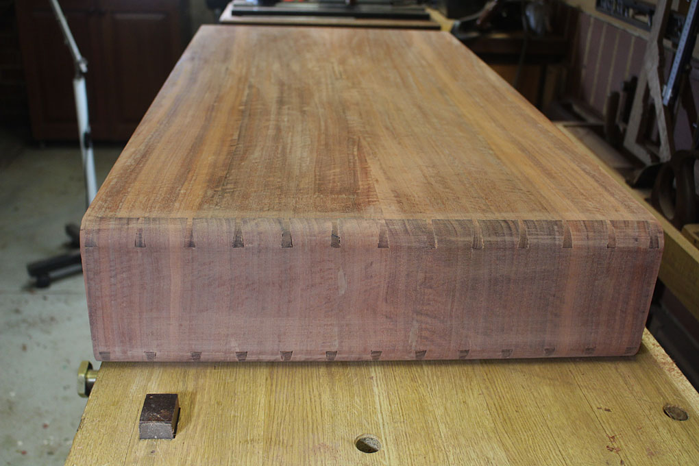
Following the method outlined previously, the two ends and the top were joined with mitred through dovetails ...

1a.jpg


One edge ...

2a.jpg


.. and the other side ...

3a.jpg


The plan now is to size the drawer case sides before dovetailing and joining the lower panel. Why the templates and sizing at this stage?

When the two ends of the lower panel have been dovetailed, the two sides of the drawer case must be fitted before the panel can be attached. In other words, these three pieces are fitted together at the same time.

Now, as the sides of the drawer case run in a stopped dado, they need to be sized beforehand. This fitting is different and far more exacting that in the typical carcase which as a stopped dado on one side only, and the dividing panels (which I term the drawer case) are slid in, allowing one to mark where the front rebates will go. In the present build, the front and rear rebates need to be determined beforehand, and cut before the parts are brought together.

The MDF template is to aid in measuring up the sides for the drawer case. This is one of the (number of) surprises of this build: it looks so simple from the outside, but when it comes to constructing ...

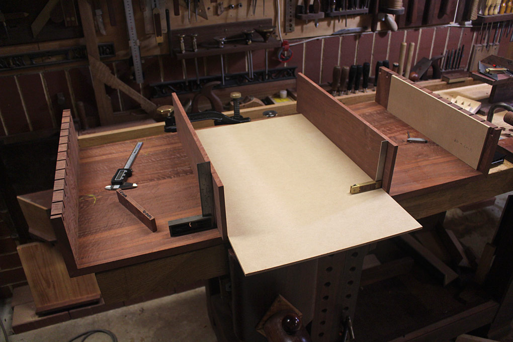
In the photo below, the dados are checked for size with a 10mm wide template ...

4a.jpg


An MDF template checks the case sides are parallel ...

8a.jpg


At the far end is another MDF template to size the drawer case sides ...

5a.jpg


That's it for now.

Regards from Perth

Derek
 
Hi Guiliano

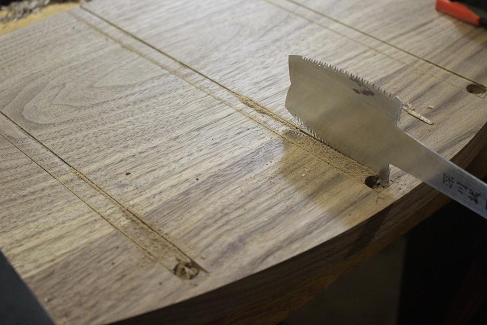
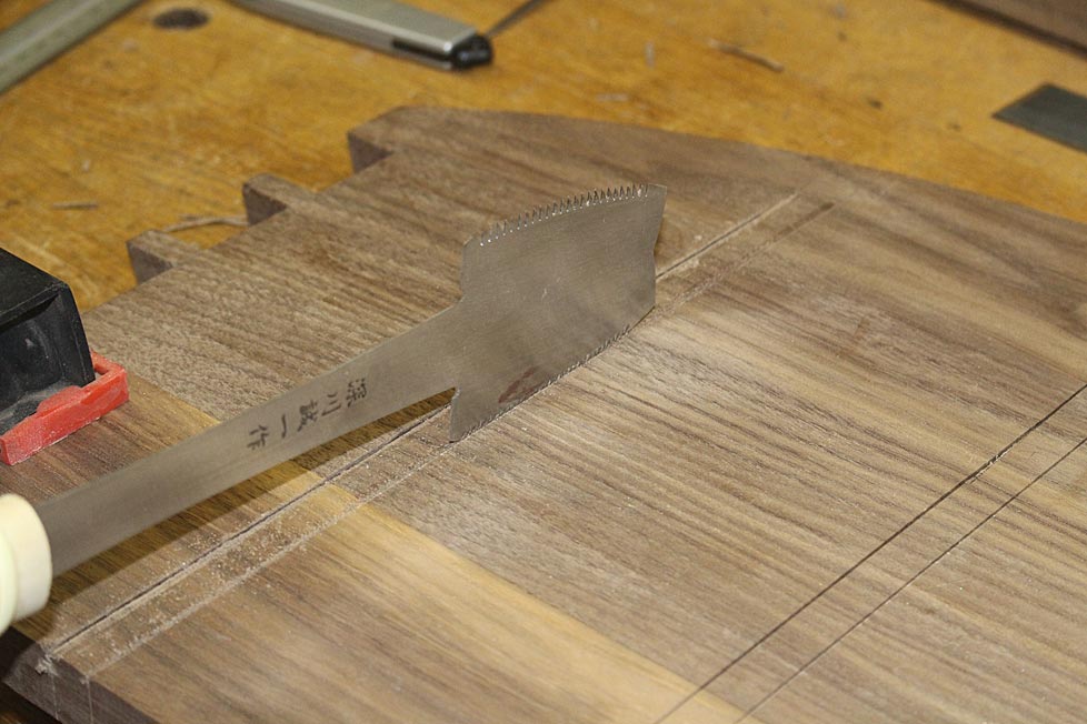
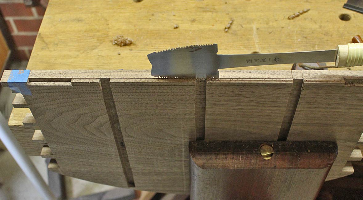
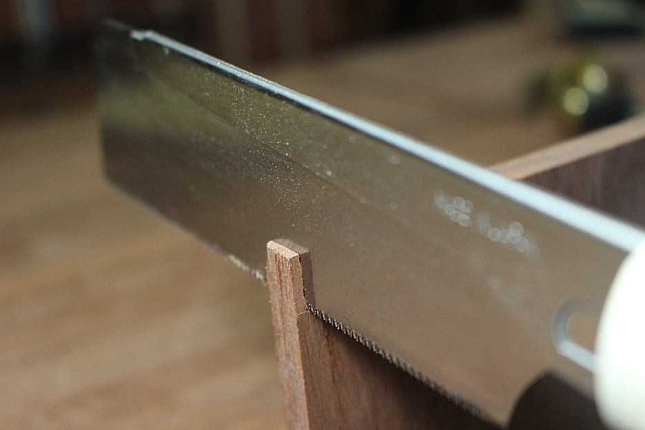
The azebiki is the only saw thta can reach into corners, as in a stopped dado/housing or to remove a section in the middle of a panel. I've written/demonstrated its use before. Generally I use it without a fence for the cut ...

ApothecaryChestPartTwo_html_m5e41181b.jpg


ApothecaryChestPartTwo_html_m5d351668.jpg


Link to article: http://www.inthewoodshop.com/Furniture/ ... rtTwo.html

Also, used in a stopped rebate ...

ApothecaryChestWeekendThree_html_m3f4e9fed.jpg


Article: http://www.inthewoodshop.com/Furniture/ ... Three.html

Most stores that sell Japanese tools are likely to sell azebiki saws.

Regards from Perth

Derek
 
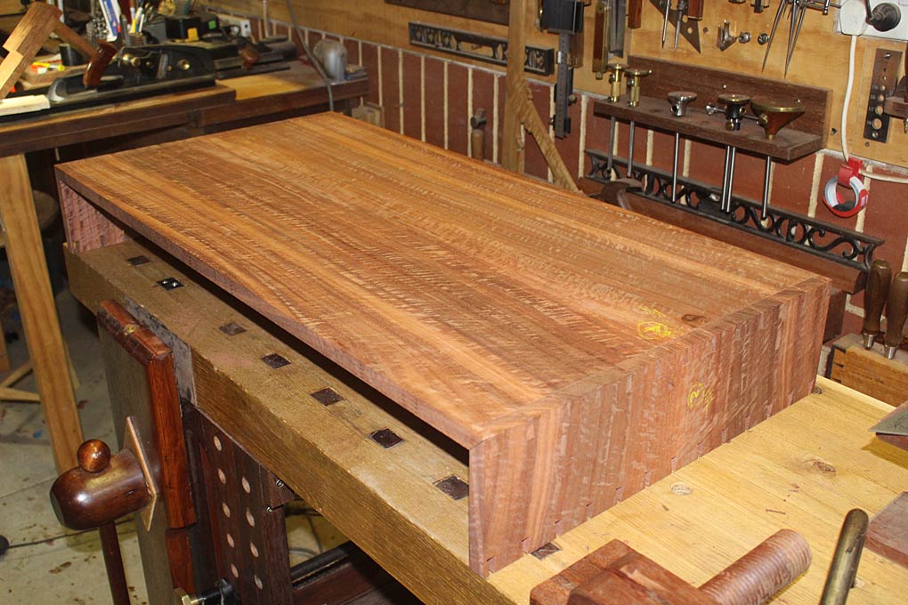
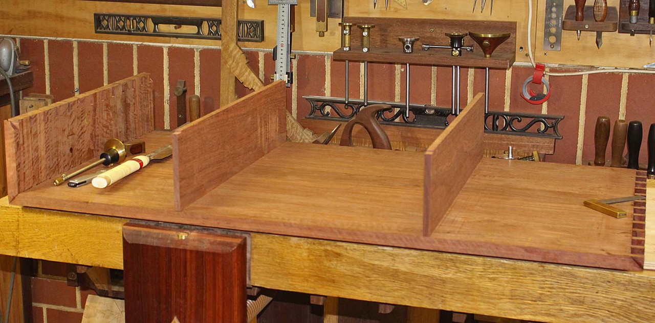
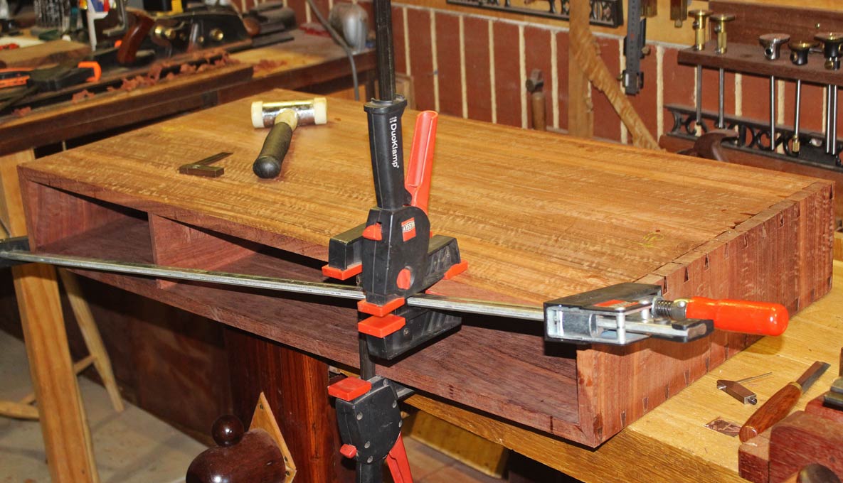
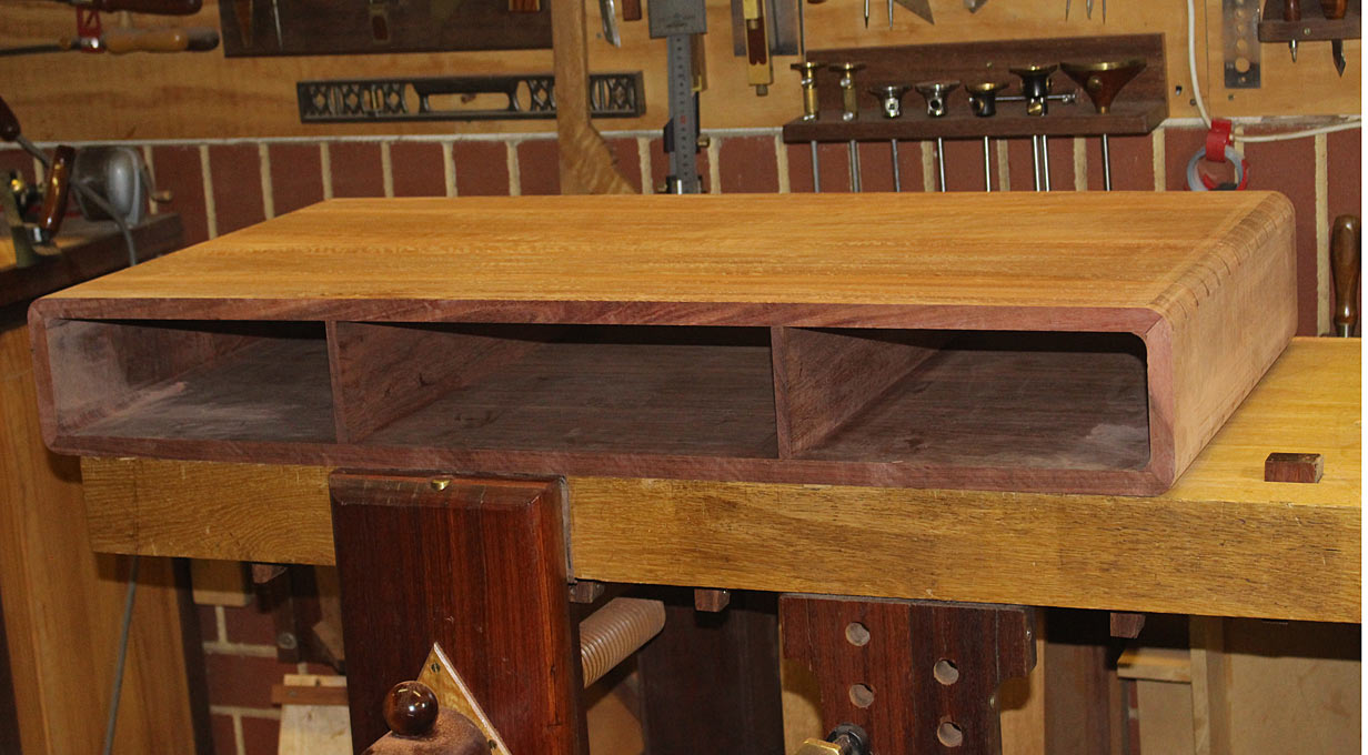
I assembled the carcase today. This began with glueing the one end and, while that dried, fitting the sides of the drawer box ...

2.jpg


4.jpg


Someone predicted that this glue up would be interesting. Was it ever.

I had this plan to glue the ends, attach the drawer box, and then simply drop the top side into place. What could be easier?

Except ... I realised as I positioned the drawer box dividers in their stopped dados - and was just about to glue in the other end - that the ends were tails and the top section had pins ... and they needed to be slid in horizontally, not vertically! The order of assembly should have been: fit drawer box to open base, add top section, now add one end and then the other.

I removed the drawer box parts, and attached the top panel to the already glued end. Lifting the top at an angle, the drawer box dividers were wiggled in. And then I discovered that they were 10mm too high!

Oh **** (or some other descriptive) .. I propped up the top panel, quickly calculated how much needed to be removed on the table saw, did both dividers, rebated the ends again ...

3.jpg


... it fits ... (phew)

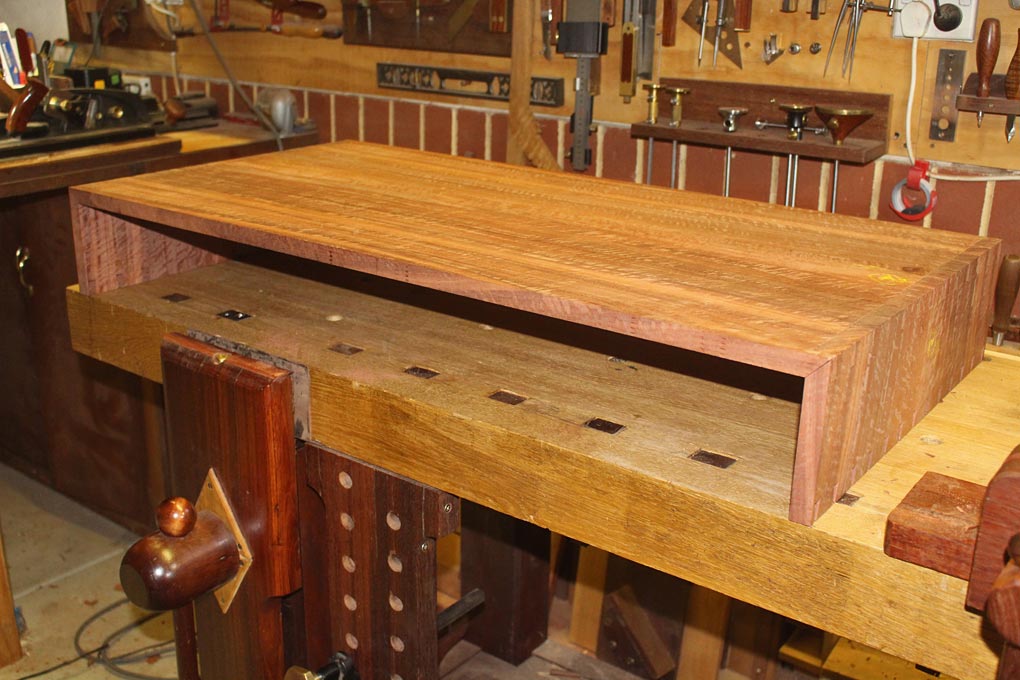
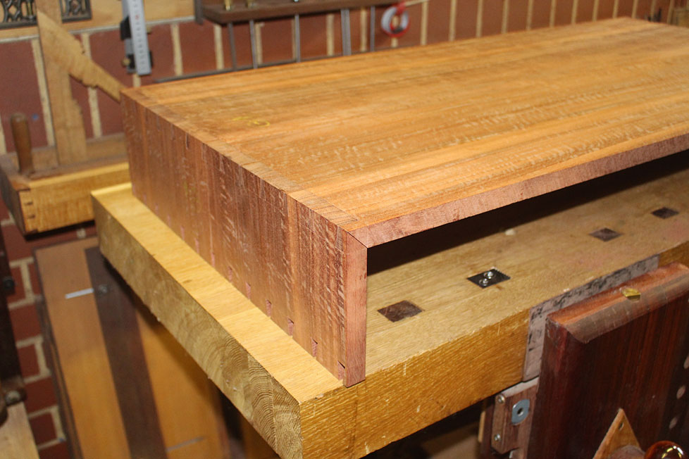
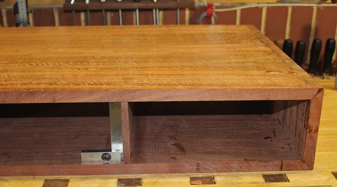
.. up ended the monster (which weighed a bloody ton, but I was now a demon possessed of desperation strength!), glued in the last side, and squared the carcase ....

5.jpg


And everything is square ...

1.jpg


I'll clean it up tomorrow, and then start on rounding the ends.

Regards from Perth

Derek
 
Hi Custard

I did read your pictorial on mitred though dovetails. Several times, in fact. It is excellent ... even if done back-to-front! :)

Incidentally, Wood and Shop website produces videos, and two days ago they posted one by Dave Heller on making London style mitred through dovetails ...

https://woodandshop.com/make-mitered-do ... ve-heller/

Dave had a few interesting comments about the making of London dovetails. I emailed him afterwards, and he emailed back. Nice fellow.

Regards from Perth

Derek
 
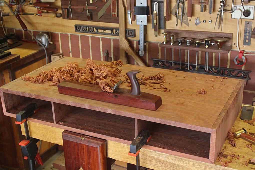
When we left off, it was with the carcase together ...

1.jpg


Step 1: clean up the carcase

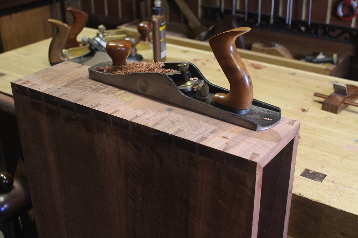
Low angle plane for the end grain and cross grain ends ..

A.jpg


Then the face grain top and bottom ..

12a.jpg


And I had a chance to use a small BU infill smoother I made several years ago on the edges. Perfect for one-handed smoothing ...

13a.jpg


Step 2: Time to round the ends.

In the test piece, it looked like this ..

24a.jpg


This lacked the inside hollowed filet. The build today starts with the making of the filet.

The first decision was that this had to be made of end grain. If it was made of side grain, the sides of the filet would be end grain, which would clash - darken - with the side grain of the carcase when a finish is applied. Fortunately, I had this one last offcut. Just enough ...

1.jpg


The filet is triangular with a hollow on the outside. I first tried shaping this with a hollow plane on a sticking board, having sliced off a triangular section on the table saw. It was impossible to do. No way to hold the wood and plane it. I tried a number of variations. I won't go there. They were all impossible. You do it, you're a better man - or woman - than me. You're probably better anyway :)

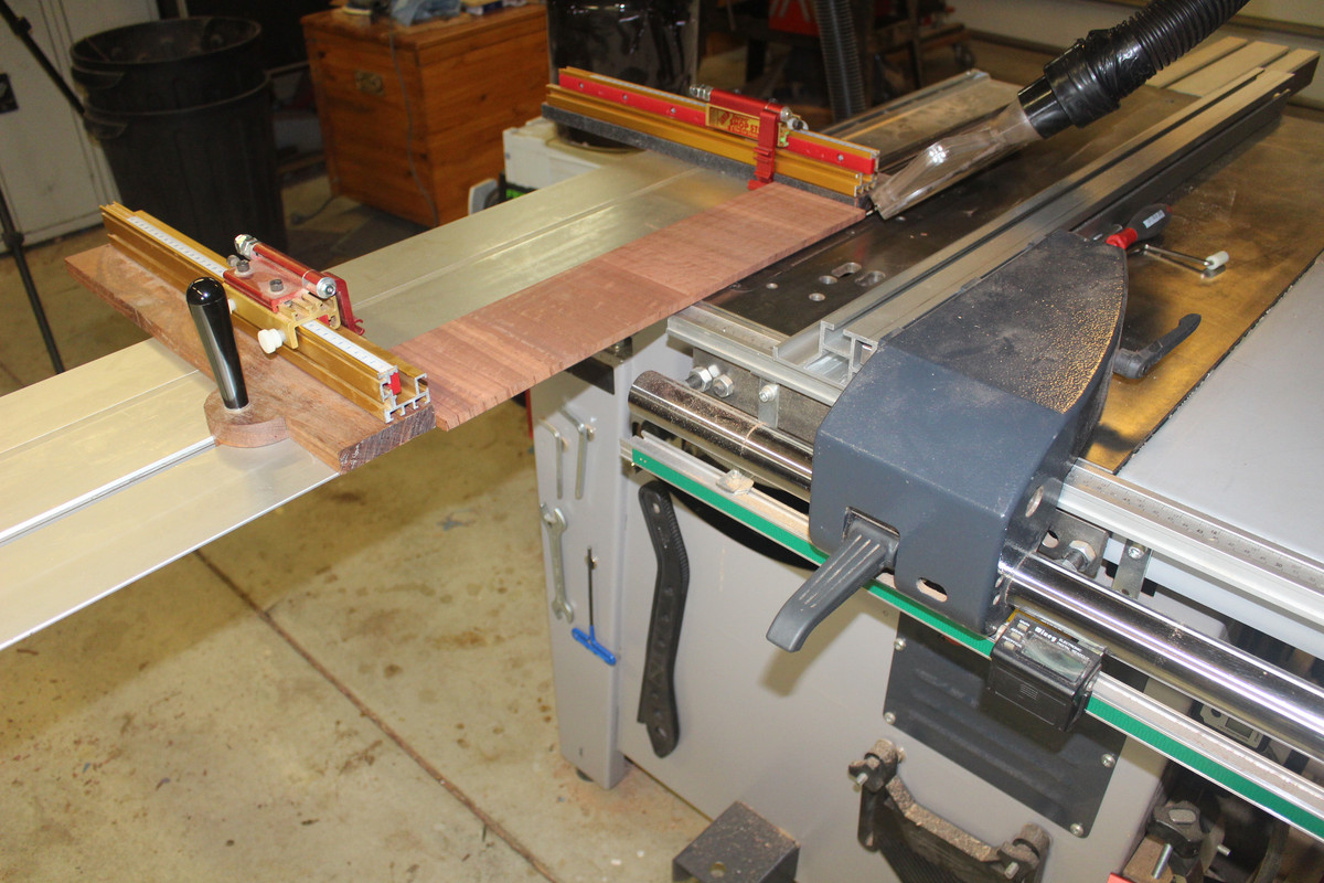
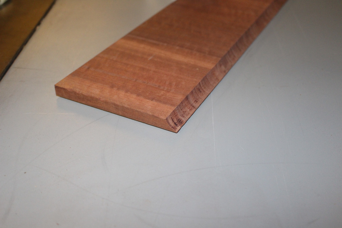
Finally I came up with this. Start with ripping a 45 degree bevel on the table saw (slider here, with board held in a Fritz and Franz jig) ...

2.jpg


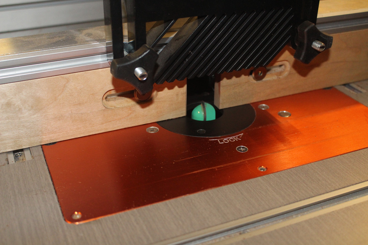
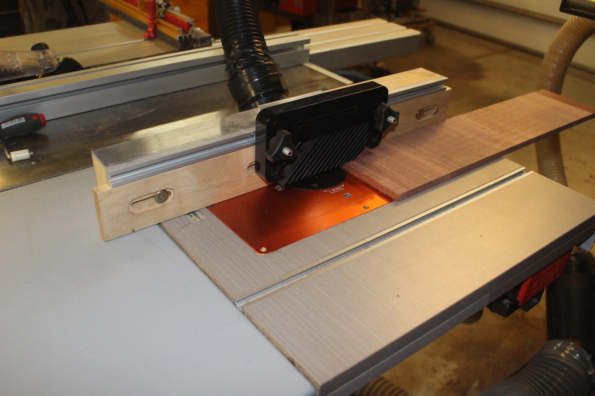
The router table is set up with a round nose bit ...

3.jpg


The mitre can be run past this and the bit will shape a round hollow ..

4.jpg


5.jpg


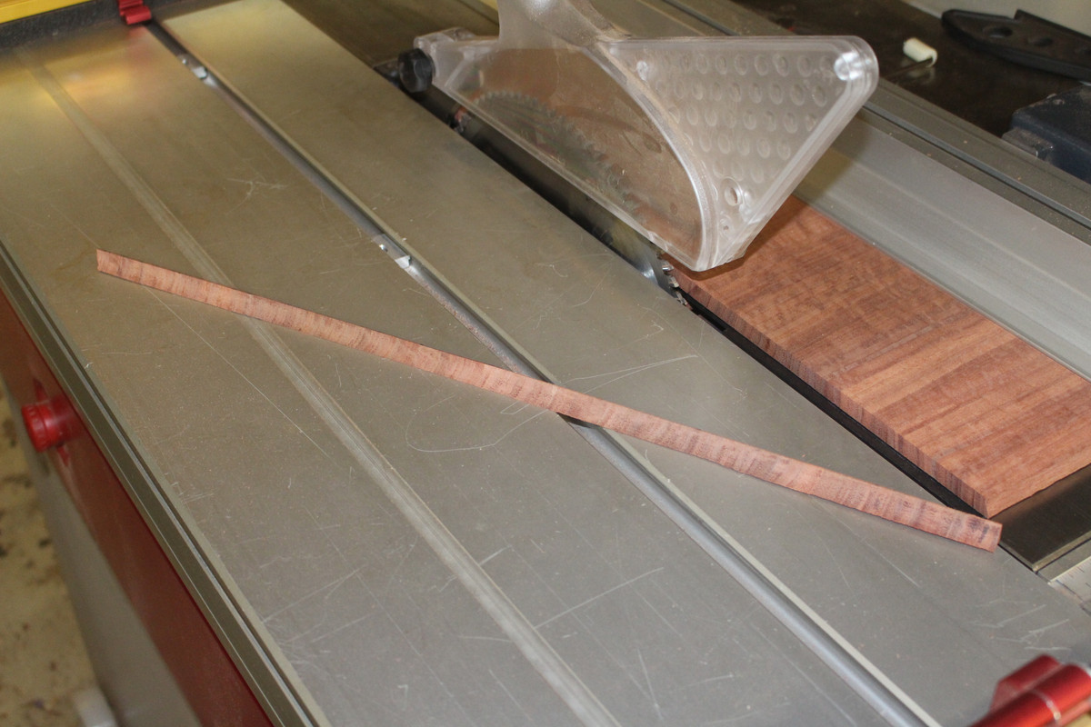
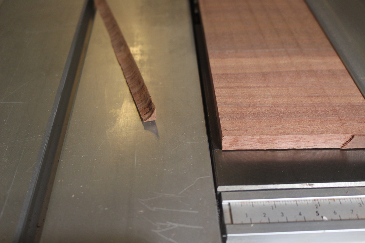
Now saw this off on the table saw ...

6.jpg


7.jpg


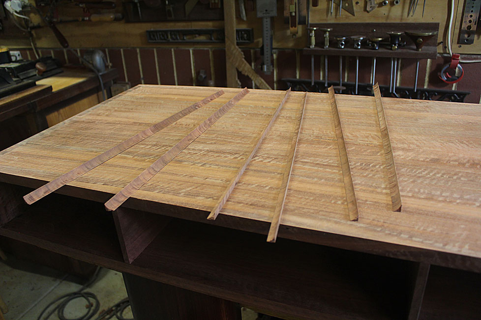
I made a bunch of them (as they are a little fragile) ...

8a.jpg


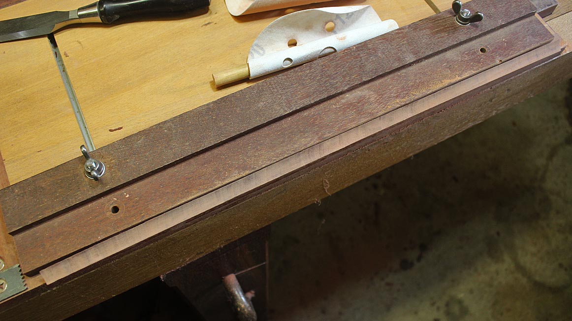
Before glueing them in, each was sanded - 80/120/240 grit on a dowel, with the filet held on the sticking board ..

9a.jpg


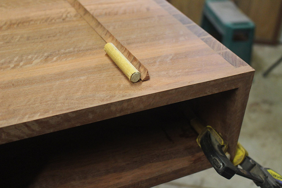
The filets were then glued in (Titebond hide glue for everything). A dowel was used to place pressure evenly on the corners ...

10a.jpg


Step 3: shape the ends

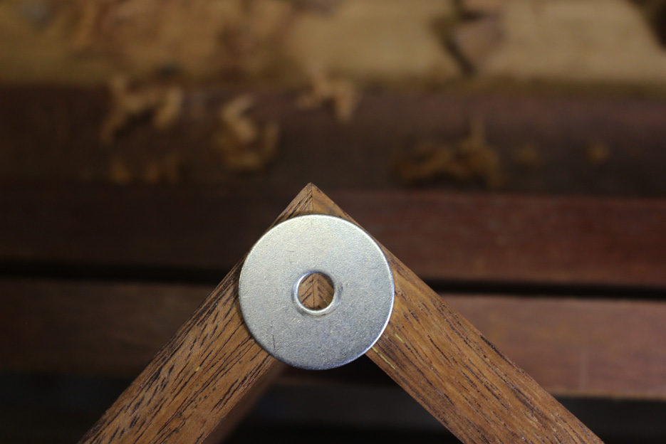
I used a larger washer than this one this time to mark out the curve (as the radius needed to be reduced) ...

23-1a.jpg


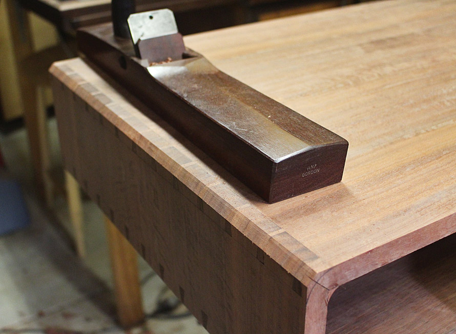
Then began planing ...

14a.jpg


15a.jpg


Refined with a block plane ...

16a.jpg


17a.jpg


... and finished with sandpaper.

19a.jpg


18a.jpg


20a.jpg


That's it for today. Next I begin the tapered and splayed legs.

Regards from Perth

Derek
 
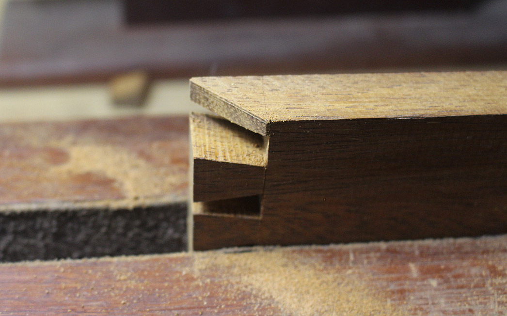
That's it, there, your reward for cutting thousands of really accurate dovetails in hard, solid wood on all your other projects. Dovetails that are gap-free beneath the surface, for as far as you need to go!
It's looking good. :D
 
This is the quality of craftsmanship I can only aspire to!
I hope one day I'll have a workshop large enough to make pieces of this quality.
 
AndyT":2anyaak0 said:
That's it, there, your reward for cutting thousands of really accurate dovetails in hard, solid wood on all your other projects. Dovetails that are gap-free beneath the surface, for as far as you need to go!

That's a really good point, and one I hadn't considered.

If Derek had used the "undercutting" approach to dovetailing that I've seen recommended, then he'd have had the depressing experience of seeing gaps open up as he planed the round over.
 
We are at the stage where the base - rail with tapered and splayed legs - is to be done next. This is the photo of the model ...

Davids-table1.jpg


I like this base, and have chosen to replicate it. The two relevant items are the angle of the splay (which I estimated as 10 degrees), and the positioning of the ends of the legs (these appear to end in line with the carcase).

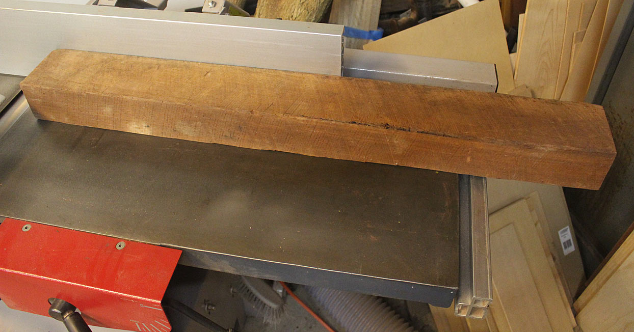
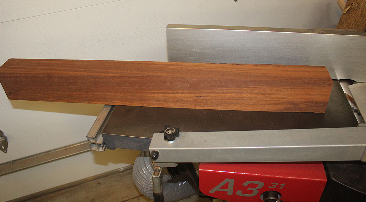
I get my Jarrah these days from an urban salvage yard, but some of it is ex-roofing beams, like this ...

1a.jpg


It is a wonderful moment when it comes out the other end ...

2a.jpg


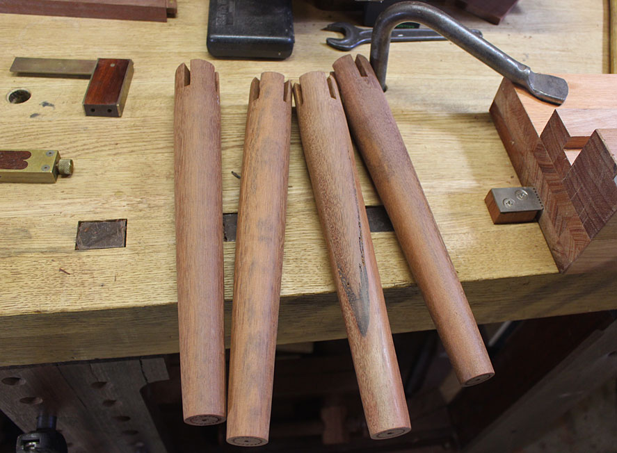
I planed up a couple of these to find 4 blanks that would make the legs. Each is 450mm long. The legs will taper in the round from 40mm at the top to 25mm at the bottom.

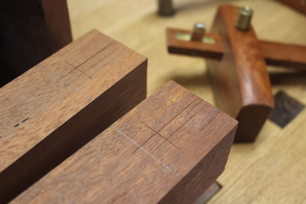
The mortices were marked out ...

3a.jpg


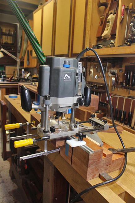
... and routed out (I have a great jig for this - just made for hard, hard woods) ..

22a.jpg


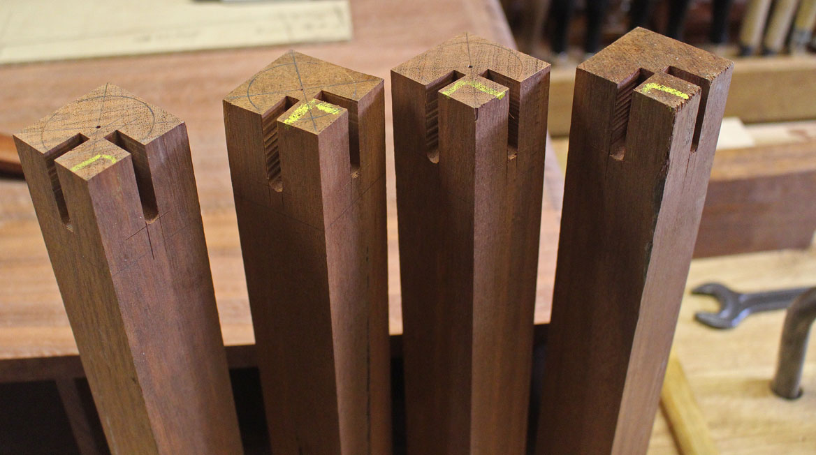
.. leaving ...

4a.jpg


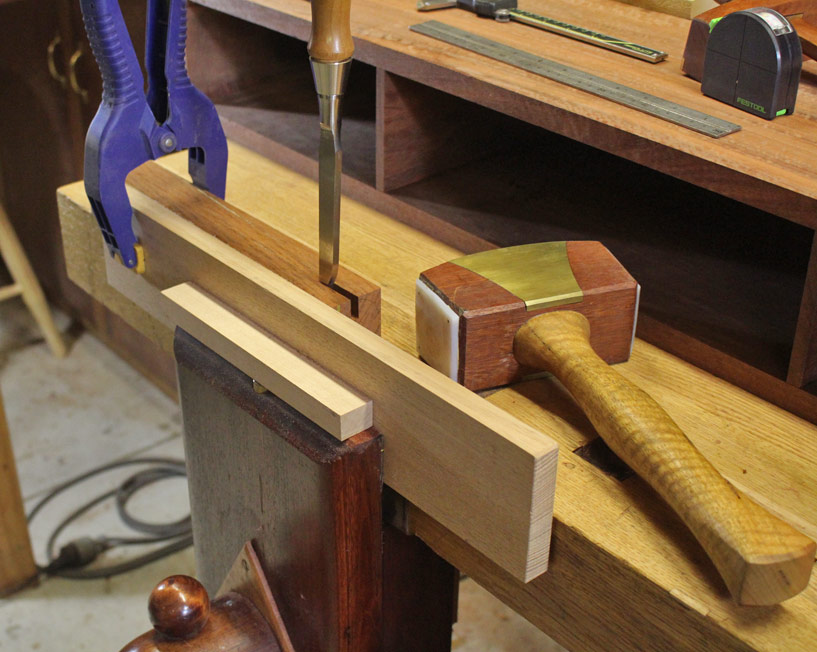
The ends of the mortices are squared up ...

5a.jpg


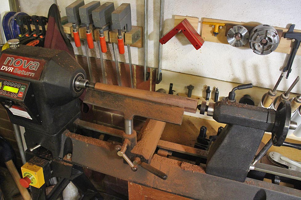
.. and then onto the lathe ...

6a.jpg


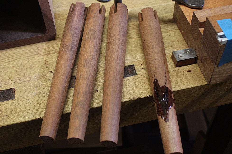
A little tinted epoxy is needed to repair some of the resin holes ...

7a.jpg


8a.jpg


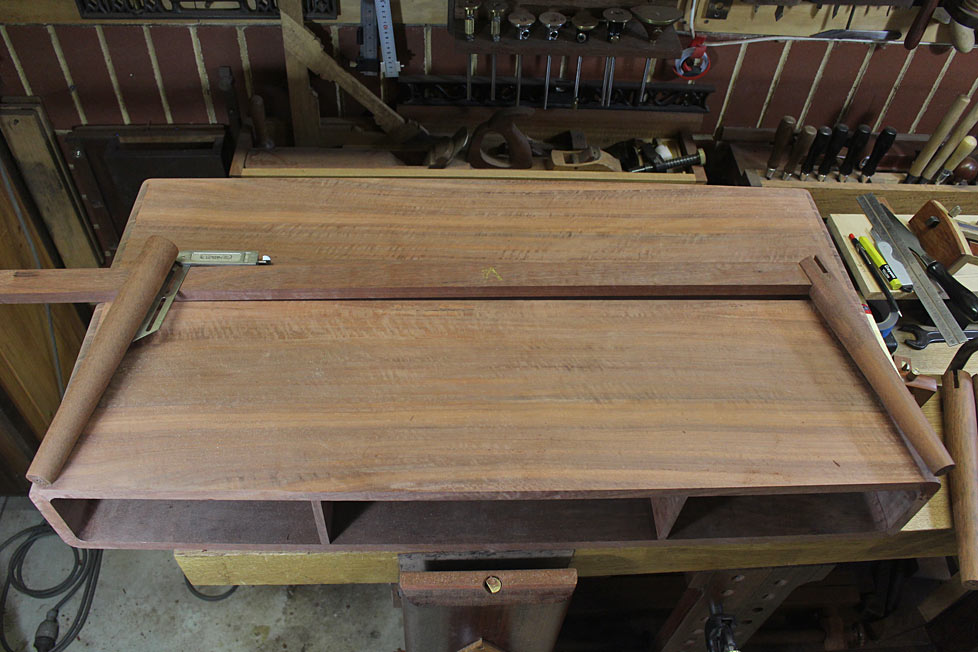
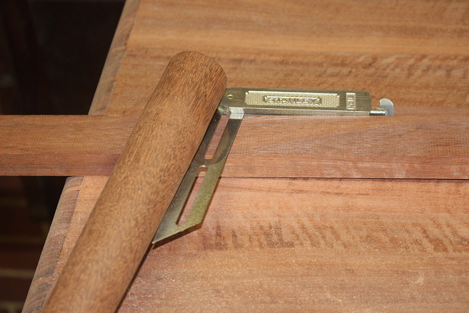
Next step is to determine the length of the rails. This is a no-math process that simply involves laying out the parts, with the legs at 10 degrees ...

10a.jpg


8-1a.jpg


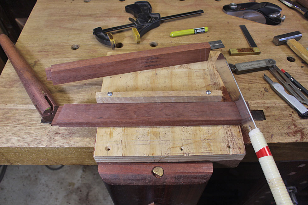
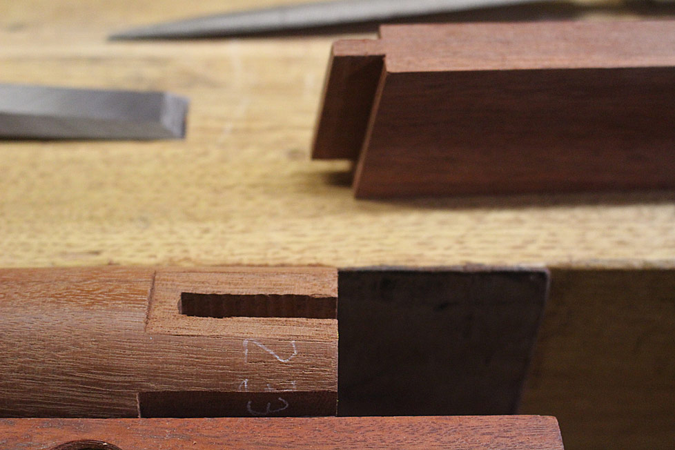
Sawing the tenons is easy enough. The rails are 19mm (3/4") and the tenon/mortice is 1/4" wide ..

9a.jpg


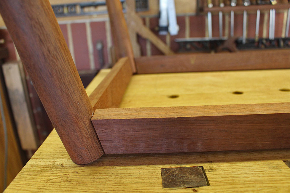
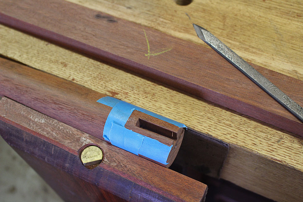
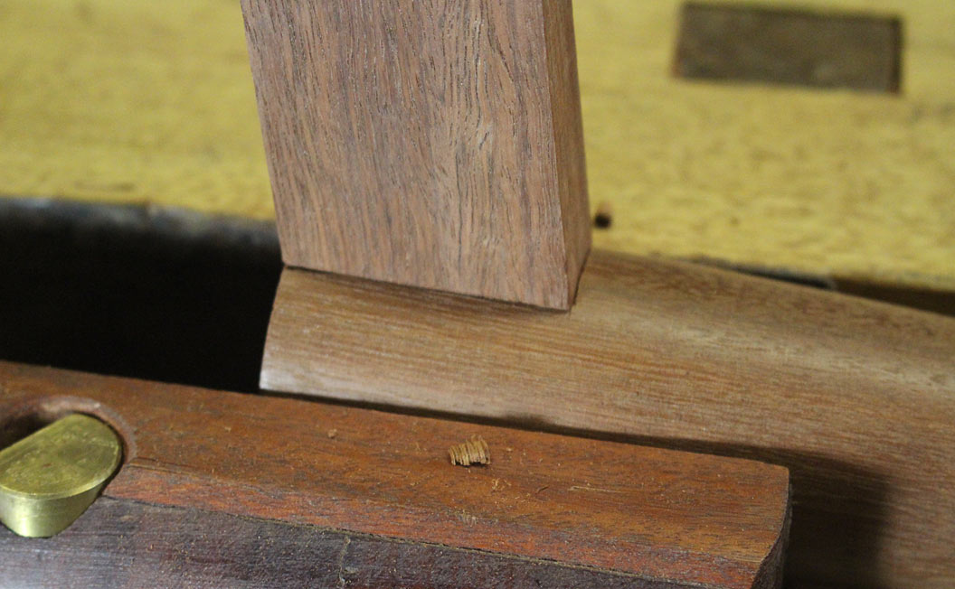
The tenon shoulder needs to be fitted flush with the leg ...

11a.jpg


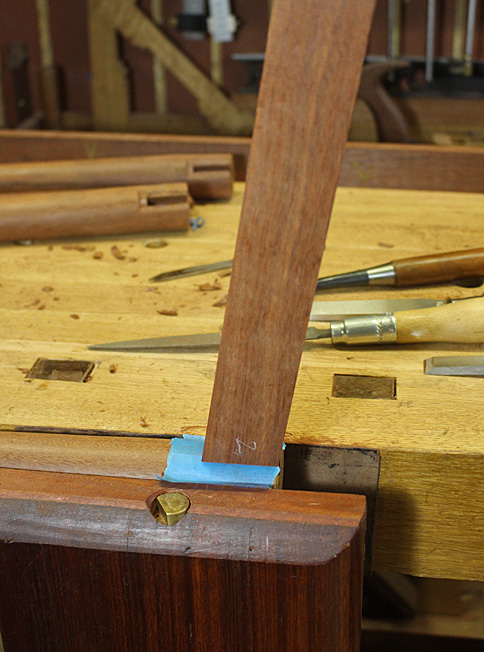
The easiest way is to use blue tape to mark the shoulders ...

12a.jpg


13a.jpg


The shoulder of the mortice is levelled with a chisel and rasp ..

15a.jpg


... until each is a good fit ..

16a.jpg


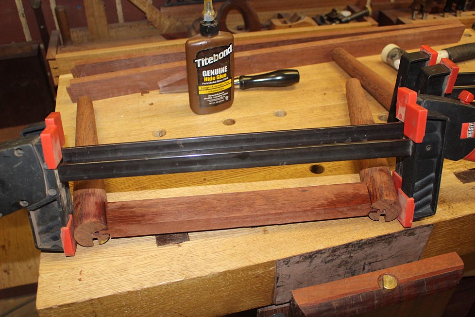
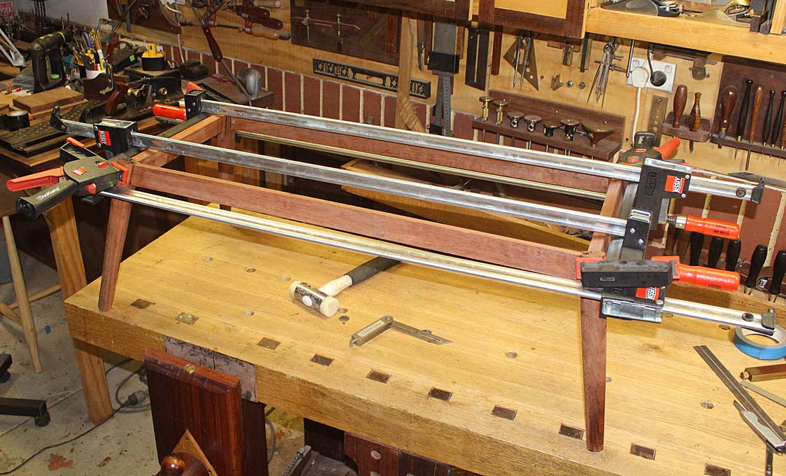
Finally, the glue up begins ...

18a.jpg


20a.jpg


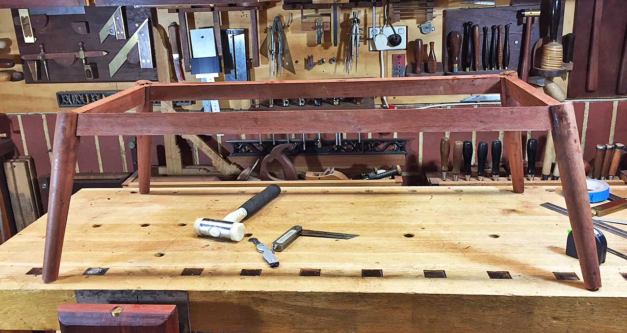
I pulled off the clamps a short while ago ...

21a.jpg


I'll clean it up in the morning.

Regards from Perth

Derek
 
Did you contemplate doing that glue-up in 2 phases, Derek? I'm pretty sure that would have been my preferred approach.
 

Latest posts

Back
Top