CAD - Computer Aided Dilemma?

UKworkshop.co.uk

Help Support UKworkshop.co.uk:

This site may earn a commission from merchant affiliate links, including eBay, Amazon, and others.

Yojevol

Clocking on
Joined
29 Jan 2017
Messages
1,901
Reaction score
1,330
Location
Wotton-under-Edge, Glos
1600340095338.png


This lovely depiction of a cabinet was posted a few days ago as an example of what can be achieved by modern CAD software with comparatively little training. What really impressed me was the standard of rendition to give a really convincing image. I have been using TurboCad for nearly 20 years and I really struggle with it to get a good lifelike image. So much so that I've given up and just rely on basic colouring techniques giving results such as this:-
1600340841704.png


where the colour of the part is merely taken from the linework colour in the basic design model. The glass is achieved by specifying the material as glass but it's not so easy when the material is wood.

Here is another example where all the linework is in brown and so the rendered view is all brown (the various shades are caused by the lighting setup)

1600342025929.png


Now here's a challenge for you budding, or even experienced, CADers; produce a Bucky Ball. An even greater challenge is to make it for real!

Richard's effort above got me thinking 'Is this ultimate realism actually beneficial in the realm of woodworking?'
I think we can consider it from 2 points of view:-
(a) from the designer/maker's and (b) from the eventual customer/owner/user's point of view.

If the designer, maker and customer are one and the same person, there isn't a problem. He can play around with the design and at the same time have in mind how to make it and what he would like to achieve as a finished job. All the capabilities of a good CAD package can help him envisage that.

The dilemma I perceive occurs when the customer is not the designer. The designer, as part of the design process, will want to achieve an outcome to the customers complete satisfaction. So he will need to produce drawings or images at various stages and in various degrees of realism. I know from my own experience that potential clients really appreciate hand drawn sketches in the initial stages. These don't need to be accurate or necessarily realistic, they just need to get over an idea.

So where does that leave you if your not much good at sketching but are an accomplished CADer? I'm somewhere in the middle but my instinct, these days, is to go straight to TurboCad and produce my initial idea there. I haven't used a drawing board for 20 years.
If I think it might be beneficial, I can produce a 'sketch' by taking a print of my CAD model and trace over it to produce a 'hand' sketch knowing that the proportions and perspective will be acceptable.

A further development of this 'cheating' process is to take a CAD view and make it look more 'hand' done by manipulation with a Photoshop type package.
Here is a corner display cabinet I made recently showing (a) the basic line drawing, (b) as rendered using the specified 'wood' material - horrible, isn't it? and (c) Photoshopped into a pencil sketch.
I've thrown in this example here just to illustrate the process, I didn't use it use it in reality.

1600351427152.png


Once the design is agreed and finalised there will be a great temptation to click on 'Full Render', print off the image and present it to the client saying 'This is what I'm going to make for you'
The danger here is that the client's expectations will have been raised to the highest levels of perfection and specification.

I once had a client say to me that it is always a joy to commission a piece of furniture because there's always a little bit of the unexpected when it arrives. It's a bit like commissioning an artist to paint a portrait. You do it based on the artist's style and reputation. You don't know exactly what he will produce but you trust that he will come up with something that will please you.

Well there is a question mark in the title so I hope that some of you CADers will add your thoughts
Brian
 
I’m not very good at drawing, but people value a sketch more than a CAD model, so I used to draw it in CAD, print it off and trace it into my logbook for that “handmade feel”.

Years ago we got in trouble for spending time and money making a concept before it had been authorised... they refused to believe the product on the hospital table was actually computer generated.

Aidan
 
........ people value a sketch more than a CAD model, so I used to draw it in CAD, print it off and trace it into my logbook for that “handmade feel”......

I do that on planning applications sometimes. I'm more than happy to sketch in 3D for clients (sometimes upside down so they can see easier), but when it comes to Planning Applications there is a duty not to mislead, so I make a proper 3D model, print it, then put it up to the window and trace over it relatively roughly.

Apparently there's a programme called "Architect's Wiggle" or something similar, which will take a 3D model and turn it into a wiggly line drawing, as though sketched by hand .
 
I worked at an industrial design firm, and although the designers there were mind bogglingly capable sketch artists, common practice was to create a bare bones skeleton in 3d CAD (pro/engineer, nowadays called creo parametric), and use that as an underlay to create a sketch. It is more efficient that way, it is actually less like cheating, because the proportions will be spot on, less risk of a customer thinking a table would be more svelte looking or a cupboard being more bulky in real life.
 
We’re CGI artists/furniture designers first and woodworkers second (hopefully the other way round soon).

In furniture/interiors sketches were the last word but over the last 10 years I feel it has swung heavily in favour of CGI’s but they have to look very close to what it will be. To the point we get photos of the actual veneers from the mill and use those on the models.

If they’re dropping a fair amount of cash they want to know almost exactly how it will look. That’s our experience anyway.

Edit: also if you use something like solidworks and build it right you can get technical drawings and cuttings lists.
 
Last edited:
Ive been using Autodesk Fusion 360, which is free for hobby or small commercial use. It's great for producing 2D drawings for construction as well as producing renders for customer approval. You can send links to customers, too, so that they can rotate a 3D model in a browser window (and see the 2D drawings). Here's a render of a table from inside.
John Ferguson Render 5.png
 
It's flattering that you picked my drawing to open your thread, Brian. I don't yet have the skills to draw your bucky ball.

However, here are my thoughts on CAD, 2d and 3d.

  • I've never needed anything more than traditional 2D orthographic projections to make furniture or joinery items using traditional woodworking methods, i.e., standard machinery, power tools and hand tools. I have used my CAD drawings to make parts on a CNC machine.

  • I use first angle projection because that's what I learnt first, and I've never seen a reason to switch to third angle. One irritation I experience with some people's CAD drawings is that the CAD jockey sometimes doesn't understand how to set out orthographic projections. They switch from first to third angle, and arrange the elevations on the 'page' randomly so it's hard to follow the logic. In other words, they have great control of the commands, but somehow they've missed out on basic drafting conventions.

  • I haven't used a drawing board and other drafting tools (T square, parallel motion board, etc) seriously for maybe a couple of decades. This is because I like the accuracy and easy repeatability of AutoCAD, the programme I used until recently. For example, if you create a form or shape it's easy to copy it, or mirror it, or get that form out of another drawing and place it in your current drawing.

  • CAD drawings save a lot of paper, but can be stored and printed out (plotted) as needed.

  • 3D stuff, such as that available through Fusion 360, Rhino, and the like is obviously a boon for use with CNC kit, and is essential for a lot of mass production.

  • CNC capabilities, including 3d printing married to CAD offers many opportunities for creativity in one-off or batch production in wood. Having said that I'm aware that most CNC work is pretty repetitive stuff to suit efficient mass production, e.g., cutting up panels and line boring for shelf pins, and boring holes for hinges in flat pack furniture such as kitchens, wardrobes, etc. And there's nothing wrong with that in my opinion.

  • As to presentation drawings I think there's a place for perspective CAD generated versions as well as hand drawn examples. I think the CAD versions can often or usually work well for single items of furniture, such as tables, cabinets, chairs, and so on, as well as for large or more complex projects. For example, they probably work very well for kitchen build outs, especially if the client can virtually 'walk through' the proposed end result. They probably work just as well for larger projects too, such as architectural proposals, but that's a bit of a guess on my part. I'm not so convinced they're always well suited to smaller furniture items; I sometimes wonder if clients expect the finished piece to look exactly like the CAD generated perspective model and are disappointed, or worse, if the reality doesn't match the rendering.

  • Hand drawn renderings of a proposed traditionally crafted furniture item (machines, power tools, and hand tools) possess a 'hand made' feel - they're personal, but get across the essence of what's intended, and the actual piece will have its own slight personal evolution on moving forward from the rendered proposal. In other words, the hand rendered presentation and the built piece of furniture are both within the skills, scope, and personality of the designer and maker. On the other hand, the CAD rendering is more influenced by the programmes tools and their capabilities, and what's put in place by the programme writers and developers and the user selects tools to achieve results. In a sense it's breaking a bit of a link between the designer's imagination and the paper, pencils, markers, brushes, rules and so on that he or she would use to create a rendering.

  • To be honest, I think there's room for both types of perspective rendering, i.e., hand drawn and CAD drawn, all depending on the skill of the designer, and the type of market in which the designer is engaged. I'm not firmly in one camp or another. I'm currently trying to develop skills in Fusion 360, primarily just because I enjoy developing such skills, and it's always nice to have the skill there if I really need it. I also really enjoy drawing by hand. I'm not particularly good at that, but I can generally get by, ha ha. Slainte.
 
I don’t think I’ve ever seen a 1st angle projection drawing. I was asked about the difference between that and 3rd at a job interview once, I explained the difference and it became immediately apparent that the people asking the question didn’t know the difference.

Aidan
 
I don’t think I’ve ever seen a 1st angle projection drawing. Aidan
Interesting Aidan. Throughout my working life I've come across far fewer 3rd angle projection drawings than 1st angle. I'd say probably ~90% 1st angle to maybe 10% 3rd angle. Increasingly though, certainly over the last ten years, I've worked to drawings that were presented neither in 1st or 3rd angle, but presented primarily as dimensioned perspective drawings or perspective with ortho faces drawings, with some additional elevations and sections.

I think 3rd angle projection drawings were/are(?) the standard in engineering, but 1st angle projections more common in furniture and maybe joinery sector. I'm not sure what I've just said is correct, but that's the impression I have. I'm more than happy to be corrected if you know different? Slainte.
 
I think both systems are acceptable as long as the appropriate projection symbol is on the drawings. When I worked for an engineering firm in Virginia, there weren't any CAD systems, so the drafting section had about 15 people working full time at their drafting tables.

One of our projects required a complex bracket to attach a piece of equipment I designed that went inside the crew compartment of the XM-1 battle tank. The task to create the drawings for the bracket was given to a newly hired European engineer. After spending a week on them, his drawings went to QC before being released for prototyping. That is when we learned there is a difference between 1st and 3rd angle projection. The 3rd angle projection was the standard in North America, while 1st angle projection was the standard for the rest of the world. He used 1st angle projection for all of his drawings.
 
I always thought 3rd was standard, however as you say there’s a symbol that tells you and the drawing is only for inspection, you manufacture off the model these days

Aidan
 
This lovely depiction of a cabinet was posted a few days ago as an example of what can be achieved by modern CAD software with comparatively little training. What really impressed me was the standard of rendition to give a really convincing image. I have been using TurboCad for nearly 20 years and I really struggle with it to get a good lifelike image. So much so that I've given up and just rely on basic colouring techniques giving results such as this:-
Based on the two images posted, it seems to be more about choice of texture images (photos of real materials, mapped onto the 3D surfaces), and the choice of renderer that's used to produce a visual from the 3D model.

The second image is what I'd consider fairly normal of mid 1990s rendering systems - limited memory for photorealistic texture images (so leaning more on procedural - mathematically generated - textures), combined with fairly primitive ray tracing (that leads to hard shadows).

The first image is clearly using good quality texture images, along with a more sophisticated lighting algorithm.

Take the two 3D models and swap them (i.e. put the first into TurboCAD's rendering system) and it would take a big hit on the visual quality.

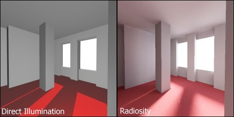
Note that I'm not critiquing the quality of the 3D models; even with a really simple model (see image from Wikipedia below) you can see there's a huge difference in realism with different rendering techniques:
Radiosity_Comparison.jpg
 
Last edited:
I always thought 3rd was standard, however as you say there’s a symbol that tells you ...
Aidan
I'm with you Aidan, though I have never used the symbol on my own drawings. I can't recall ever seeing a 1st angle projection drawing in 70+ years (I started technical drawing at a very young age! ) I'm also not too precious about having the plan view above or below the elevation - sometimes using both for clarity and even neither if there's nothing to show but the outline.
 
What is the difference, anyone got an example done in both so I can see ?
Many very wordy explanations exist...
https://wonderfulengineering.com/di...ngle-projection-mechanical-engineer-explains/
I’ve always described it as in one the part moves relative to you, the other you move relative to it, imagine it in the bottom of a goldfish bowl and being moved north, south, east, west etc.... that’s 3rd.

Eitherway, it’s noting special and once you think that way you can read an engineering drawing like a musician reads music score

Aidan
 
projection.jpg


Some people prefer 3rd Angle because it puts the view in the correct position in relation to the viewpoint, ie, the view looking down onto car roof is placed above the car.
Brian
 
So you're the culprit that gave us the Austin maxi, shame shame shame Brian
:eek:
 
Back
Top