Angles?

UKworkshop.co.uk

Help Support UKworkshop.co.uk:

This site may earn a commission from merchant affiliate links, including eBay, Amazon, and others.

stuartpaul

Established Member
Joined
11 Feb 2003
Messages
1,062
Reaction score
59
Location
Somerset
The idea is to make a couple of boxes similar to the attached. Final sizes haven't been determined yet but in the region of 200 mm by 100 mm and about 100 mm high.

Material will be about 6 - 8 mm thick.

I've been puzzling on the angles for the top which are clearly compound mitres and not just 45 degrees.

Anyone know of a way of accurately calculating them? I know with the inlay I can cheat and use that to fill gaps but I'd like to get it reasonably accurate!
 

Attachments

  • box.png
    box.png
    79.6 KB
It is a mixture of 45 degrees on plan and the pitch of the sides, say 30 degrees.

On a mitre saw or sliding table saw, you need to set the saw angle to one and the saw body turn ( mitre saw), sliding fence (table saw) to the other.

Alternatively on a mitre saw, you could make a saddle to the side pitch, then do your cut at 45 degrees.
 
You do it the trad way. Basically draw a "projection" which is as if the box was thin card folded out flat.
 
You have obviously created your design in sketchup which has the ability to work out all the geometry for you as it creates in 3d, surely you could make all sides into individual components then use the measure angle tool to setup yuor saw
 
Jacob":7tyo0gil said:
You do it the trad way. Basically draw a "projection" which is as if the box was thin card folded out flat.
Actually a bit over simplified. You treat each component as a thin paper box so it'd fold out edges and all.
Easier than it sounds once you get into it, believe it of not!
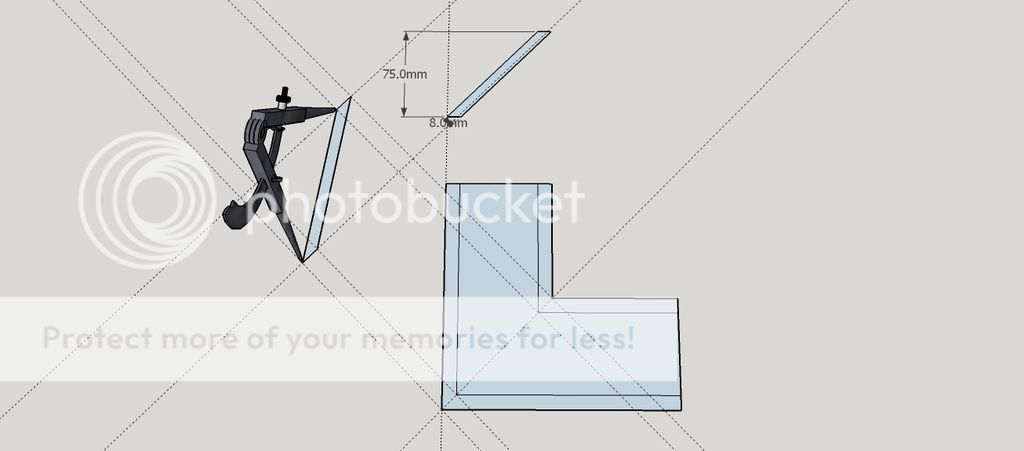
 
I used an online calculator when I made a tray. Google "compound mitre (or miter) angles". I am on my phone or would give you a link. Cutting to a fraction of an angle is another challenge.
 
I had a fiddle with sketchup but couldn't see how I could get accurate angle measurements, - I'm not an advanced user!

Jacob, - that's the route I was heading down until I followed Marcros's advice and found a calculator, - setting up and cutting to those angles is however another question!

Plenty of practice and I suspect plenty of swearing!
 
What angle is formed between the leaning sides and the horizontal? If I know that I can quickly tell you the other relevant information for the compound cuts. Slainte.
 
Sgian Dubh":2fgqke6c said:
What angle is formed between the leaning sides and the horizontal? If I know that I can quickly tell you the other relevant information for the compound cuts. Slainte.
Richard,

According to my calculations (!) it's 33.7 degrees and using one of the online calculators this gives a mitre of 29 degrees and a bevel of 36 degrees. Without a protractor handy these seem a little on the low side to me so if you could double check I'd be grateful.

As the design isn't yet finalised (currently based on double cube) I'd be happy to change things around to provide more convenient angles.

It all seemed so simple when I started ........

Edit - a look at a subsequent siteoffers different angles :roll: of 39 degrees mitre and 23 degrees bevel
 
stuartpaul":19qpsjp9 said:
Edit - a look at a subsequent siteoffers different angles :roll: of 39 degrees mitre and 23 degrees bevel
This set of numbers is correct, or as near as you'll be able to achieve given the limitations of most saw protractors.
I don't bother using parts of a degree for such calculations and go for the nearest whole degree - the numbers are fiddly enough for our purposes without overly complicating the issue. So I used a 34º rise of the sides from horizontal to calculate, and the results are:
* dihedral angle = 133.4º. Halving this gives the requisite bevel (saw tilt) for a mitred intersection of the two planes = 66.7º: set the saw to this to cut it, or the complement of 23.3º if your protractor happens to read that way.
* mitre angle = 50.3º. Set the mitre gauge to this angle, or its complement of 39.7º if that's the way the protractor reads.

You should be able to set both those angles on your saw's protractors to within half a degree or so, which will give you a good result if executed carefully. Slainte.
 
There is of course another way to project the angles by using geometry.

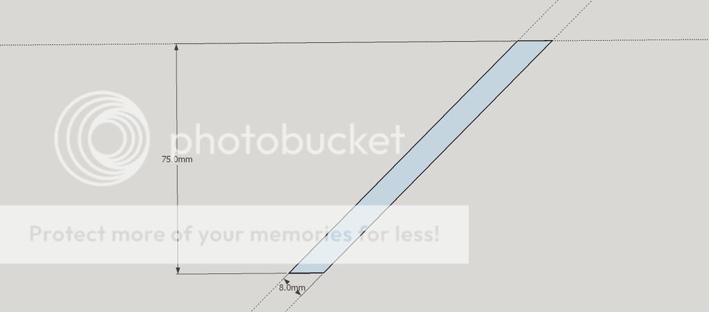
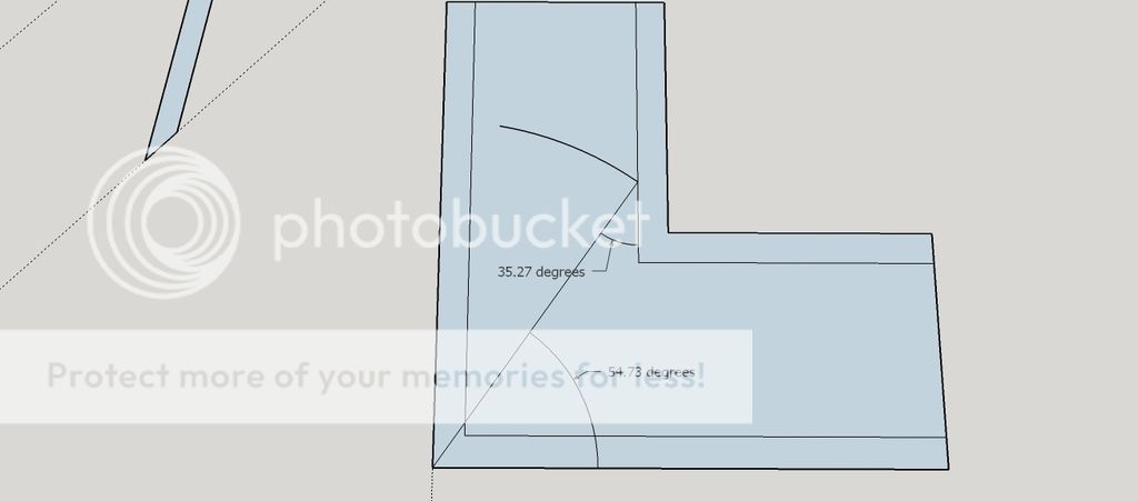
Looking at the original attachment I’ve assumed the pitch of the slopes are 45 degrees and a material thickness of 8mm

Start with drawing a vertical section through one of the slopes as such


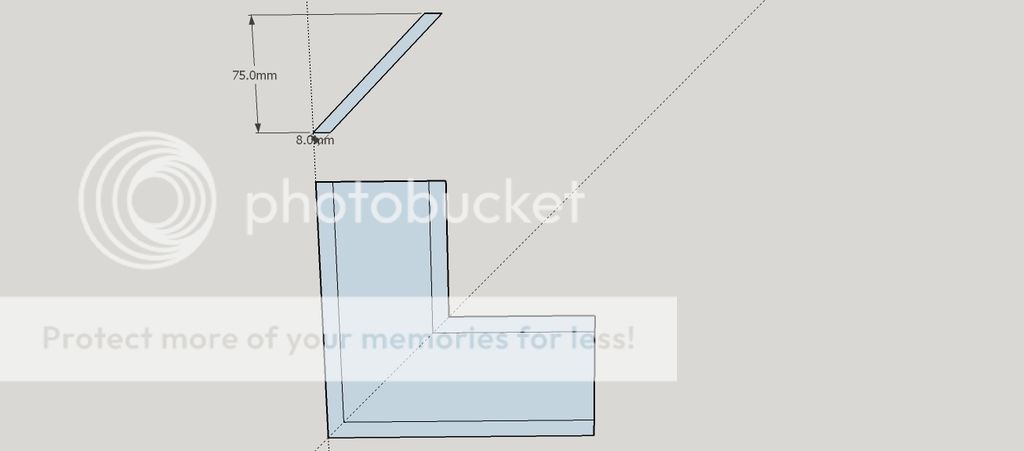
Then from that draw one corner in plan


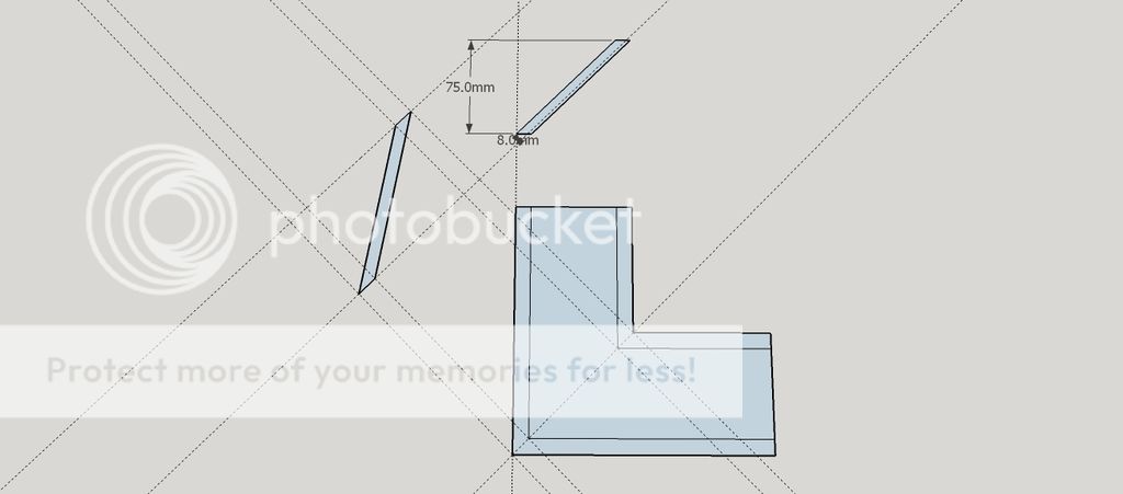
From this project one of the corners at 90 degrees to the 45 degree line, this will give you the true length of one of the corners (or hips in roofing terminology)


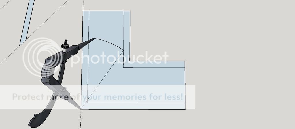
With a pair of compasses set them to the corner length


Then place the compass point on the corner of the plan and mark the point where it hits the outer top edge of the box


Strike a line from this mark to the boxes corner; the two angles formed from the vertical and horizontal on plan are what you are likely to set the mitre fence on the sawbench too


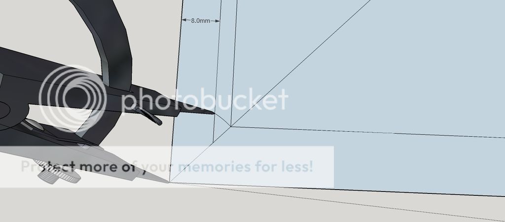
Now for the bevel angle of the mitre. On the plan scribe a line the thickness of the sides (in this case 8mm) in from the edge


Now reset the compasses to the mitre length of on of the sides in plan (including the top/bottom bevel cut) and scribe it round to where it hits the true thickness line


Now again join this point to the corner of the box in plan


And this gives you the bevel to tilt the saw blade too

Therefore you can project all the angles as identified, set your bevels to the angles directly from the drawing and then set the saw up from the adjustable bevels or if used regularly make ply/mdf templates of the angles to set up the machinery

Hope this helps
 
katellwood":12dyxvjr said:
There is of course another way to project the angles by using geometry.

Looking at the original attachment I’ve assumed the pitch of the slopes are 45 degrees and a material thickness of 8mm

Start with drawing a vertical section through one of the slopes as such
................

And this gives you the bevel to tilt the saw blade too

Therefore you can project all the angles as identified, set your bevels to the angles directly from the drawing and then set the saw up from the adjustable bevels or if used regularly make ply/mdf templates of the angles to set up the machinery

Hope this helps
Thank you for taking the time and trouble to go through that and post it.

Interesting approach and shows how lazy I've (and I suspect others have!) got due to this interweb thingy!
 
Hello,

Don't bother with calculations! For a TS:

Rip a length of planed timber to the angle of the 'roof' sides. Screw this to a mitre fence as an auxiliary and set mitre fence to 45 degrees. One just places box sides against auxiliary and crosscut, simples!

For a mitre saw just make angled auxiliary for back fence, set mitre saw to 45 and away you go.

Mike.
 
It's a pyramid with the top cut off. The fact that two sides are longer doesn't matter - the angles are the same.

Simply break the problem down into triangles, and use Pythagoras's theorem and sines/cosines/tangents to get what you need. Triangle angles always add up to 180 deg, too.

Start with what you know: the slope angle of the sides and the length of the ends (long sides don't matter for this, as I said). You can work out everything else from that, pretty easily.

The tablesaw system from Woodbrains will work really well, except that the cumulative error may give you joints that don't fit well, unless you're really careful about setup. If you are careful, it should be great.

. . .

I did an octagonal sloping roof for a bird table a couple of years ago. I didn't have a working table saw, but I did have a good mitre saw, so auxiliary fences weren't really an option.

I bunged the calculations into a spreadsheet (hint: go across - work on a couple of columns and put the result in a third, then do the next bit using that column, and so on). It worked really well, and eventually I could "dial in" the circumference and height I wanted, and the numbers just dropped out. Assembly was simply holding the joints together with masking tape, flat on the bench, then pulling it up into the right shape.

With anything pyramidal, if the angles are slightly sharper than correct, you won't see the gap on the outside, so err that way if you can. The octagon thing has more calculations, but it's essentially the same as for a square pyramid.
 
Here's another method of drawing to ascertain bevel and mitre cuts for roofs, essentially the same angles as required for pyramids. I can't recall the source, but it came out of a standard carpentry and joinery text book. Notice in this drawing I used the same 'roof' pitch as used in my last response, and that the angles given in the drawing are the same as the angles I gave then. Years ago I used to draw these on a parallel motion board to find the requisite information, but no matter how carefully I drew there were always errors large enough to bug me. Errors were caused by everything from the thickness of the pencil lead, to slight movement of the paper, or clumsy use of squares, etc.

Digital drafting, as in the linked drawing above, makes life a great deal more accurate, although even with this there can be slight discrepancies caused by limiting the number of decimal places to maybe none or just one (working in millimetres). The discrepancies are small and insignificant, but nowadays I generally refer to a spreadsheet to find out the required angle settings - it's a lot quicker, ha ha. Slainte.
 
It used to be taught as standard practice, essential for roofs and framing but also for sorting out smaller stuff with funny angles. It's a major part of the almost lost art of graphical calculation techniques*, as used from the year dot in many industries, architecture, ship building etc. and described in detail in all the old books.
And it generates "the rod" - the most useful, powerful and essential technique which all woodworkers should know about. Very accurate and precise work can be set out without calculations, even without any measurements if necessary.
We did saw stools, and I posted up the method here. Full size on ply.
Intimidating at first but you soon get the hang of it!

*PS otherwise known as geometry. We did all that euclidean stuff at school but it wasn't until I became a woodworker that I had much use for it!
 
You're right about drawing out this sort of stuff being standard practice in a previous era, Jacob. I was taught quite a bit of it a long time ago - arches, dihedral angle development, quatrefoils, trefoils, small breaks in mitred mouldings, raking mouldings to horizontal mouldings, oblique cones, and the like. I don't readily recall the method for pretty much any of them now, but luckily, I still have many of the text book instructions which I can turn to when required. Slainte.
 
Back
Top