my DX5000 dust extraction system (with revised section)

UKworkshop.co.uk

Help Support UKworkshop.co.uk:

This site may earn a commission from merchant affiliate links, including eBay, Amazon, and others.

head clansman

Established Member
Joined
7 Jan 2008
Messages
1,562
Reaction score
0
Location
UNITED KINGDOM
Hi all

This is my extraction system started last yr, now just about finished all but for crossing the t.s and dotting the I.s

I wanted to get the best from the system, I didn’t want to spend a heap of money and time fitting all this equipment and then not to be able get the best from it , I first spent a heap of time planning where machines and pipe work would go then slowly a plan came together, first I wanted as much suck as possible so decided to keep pipe runs to a minimum , but with each machine requiring a piped run to the blast chamber at first it was a nightmare I didn’t want all those pipe running over head like a spiders web going off at all different angle and all leading to one blast chamber that you see in so many workshops I decided on one hard pipe feeding all machine , which in turn had to feed the two system that I had decided on, it would also mean a long length of pipe connecting all machine possible running in all direction, this I didn’t like either.

The system incorporates two sizes of pipe work.

50mm 100mm for machinery.

50mm for light dust for hoovering & hand held power tools to cope with MDF dust, hence why I decided to design my own system in the first place.
This bought about my final plan to keep hard pipe work to a bare minimum I decide to split the workshop down the length with machinery on one side and working area on the other this gave me what I wanted the shortest possible hard pipe run of 1.9m including the blast chamber with an air/debris lift of 800mm to the inlet port on the extractor.

In the blast chamber there are three blast gates, the blast chamber is 600mm long from the left black blast gates to the right steel blast gate and there is one 50mm blast gate connected via the 50mm pipe work which is 300mm above the 100mm hard pipe work , plus one 50mm Hoover point .

I also designed it for a minimum lift for all wood debris & dust hence why I didn’t want to go overhead unless I really had to , then only if it was to be lifting dust , so decided to drop as much pipe work to within(600mm) from the floor level . (Minimum lift).

After I got to this stage I could not find a blast gate to fit the 50mm pipe work So I made the blast gates which are a good starting point for this thread.

50MM PVC BLAST GATES

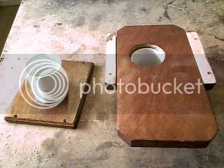
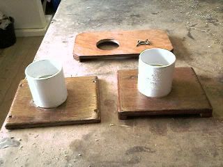
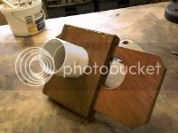
All the 50mm blast gate were made from PVC piping which all came from a company who sells a product called FloPlast here in Weymouth www.floplast.co.uk/ on the trading estate which I’m sure many of you can obtain if you so wish . The blast gates are made from two straight couplings, two short length of pipe, and some off cut of 3/8” plywood left over from when I constructed my workshop, the short lengths of pipe are first glued into one end of both couplings and then the coupling glue into the suction hole in the ply wood which are shown as follows
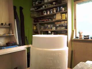
Photo-0014-1.jpg


Above showing short length of pipe work before gluing
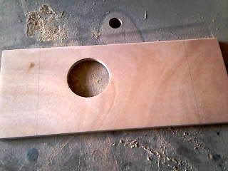
Photo-0127.jpg


Showing suction hole

Photo-0128.jpg


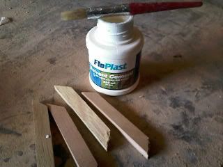
Showing glue bottle and hand grips to be glued
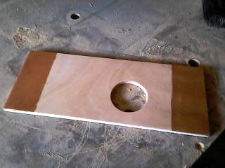
Photo-0129.jpg


The dark areas are wet glue before hand grips were glue
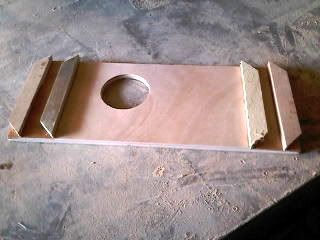
Photo-0130.jpg


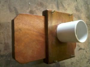
This last photo here shows a double hand grip glued , but that was changed , I didn’t like it so I cut off the outer two at either end, all other were then made with only one hand grip either end.

****************************************************************
This is the revised section that I missed out during the original post.

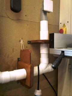
Shown here is how I assembled the blast gates .
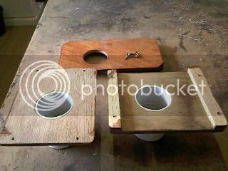
Photo-0049.jpg

Photo-0052.jpg

Photo-0051.jpg

Photo-0053.jpg

Metal strip shown on edge of a completed blast gate so it can be fixed to wall and secure pipe work in position .
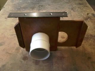
Photo-0051_1.jpg


These two pics here show the blast gates in the vertical position closed and opened , just kept simple with a length of cord and a screw,
(just for you rob (woodbloke))
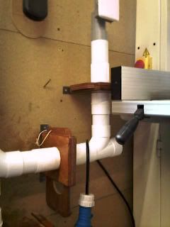
Photo-0049_1.jpg

Photo-0050_1.jpg


END OF THE REVISED SECTION
****************************************************************


These shots are showing the assemble blast gates from various views.
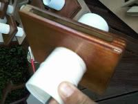
Photo-0123.jpg


Photo-0016-1.jpg


Photo-0015-1.jpg


That just about covers how I went about making these blast gates.

The 100mm blast gates I decided to buy only because I could not find 100mm straight couplers at the time , and partly because of so many other thing going on in my life at that time , but in hindsight I wish I had researched for them a little longer. I used 100mm black plastic ones from Axminster tools, which also can be purchased from just about any good merchants , these get blocked with saw dust in the corners and then the gate won’t close properly so you lose suction, three has broken all replaced with metal blast gates.

50mm & 100mm ducting.

As mentioned, the main hard pipe machine ducting run is a total of 1.9m including the blast chamber of 600mm, so let’s start from the chamber and inlet pipe to the extraction inlet pipe which is 1.4 mm above floor level.

The three photos show the entire length of hard pipe ducting run (left) 1.1m. (Middle) is the blast chamber 600mm width 800mm height. (below) the entire lengths of hard pipe ducting run 1.9m including blast chamber.

Photo-0028.jpg
Photo-0034.jpg
Photo-0036.jpg


flexible pipework.

From the blast gates these run to all machines independently in 100mm flexi .

Circular saw.

I have the saw mounted to on a turntable so no matter what position I lock the turntable in the flexi remains connected at all times along with the overhead saw guard.

Photo-0023_1.jpg


The first photo shows saw set at 90 degrees across the length of the workshop.

Photo-0018.jpg


This photo shows the saw turned another 90degrees to the right still connected to the flexi pipe.

Planer

This again has a100mm pipe fitted permanently so I can easily change from overhead planing by simple opening the Planer beds and changing to thickness mode the flexi length is 2.5m

Photo-0032.jpg
Photo-0030.jpg


I have stated that I split the workshop down the length with all machine to one side of the shop, not quite correct with the one exception of the band saw 100mm and 50 mm Hoover point which I had to go overhead with both pipe runs, this pipes can be seen rising vertical in the centre of the right hand photo of the ducting hard pipe.

Photo-0036.jpg


50MM DUCTING

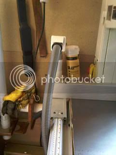
I fitted this for the extraction of dust from all power tools i.e.: router sanders and of course a Hoover system so I could get rid of all portable Hoovers and dust bucket plus leads and flexing pipes everywhere, I found this company www.cvcdirect.co.uk and bought three Hoover socket and a seven meter hose which when I plug into two of the sockets I can reach all corners of the shop from both sides of the shop for cleaning dust , the third socket still to be fitted which will be used outside the shop but plumbed through the wall into existing pipe work , so on those warm sunny day when I get to work out side to work I can Hoover all the decks and keep them clean as well .

Photo-0023.jpg


Showing pipe runs crossing the shop.

Photo-0026.jpg


Showing Hoover point in lower section of photo where the third Hoover point will go out through the shed wall.

EXTRACTION UNIT DX5000 TWIN MOTORS

Photo-0037.jpg


shown here with blast chamber, the steel blast gate will be connect to the lathe on the right via the pipes that can be seen in the photo.

Bits and bobs

Still to complete, the placement of a couple more Roding eyes in the 50mm system and the fitting of one more Hoover point.

Conclusion

The only down side of the hole system is the amount of dust that collects under the saw , I stress here not because of lack of suck but the bad SIP design around the saw blade , which is being discussed here at the moment on this very forum , wish they would hurry up and conclude all the design changes they keep coming up with , I’m following that thread with interest.

Photo-0019.jpg


Well guys & girls hope you have enjoyed and it may be of help to someone out there, I know I enjoyed putting it all together, it’s taken a long time and a lot of money but well worth the effort it’s now finally has come together.
Hmm now what do I do now, ah yes complete my infill planes, my tool cabinet, and then ah yes, start my new bench. hc
 
Cheers, Martin (not least for the link to the vacuum cleaner supplies site!).

I had similar grand plans but, for the time being, I'm sticking to moving a hose between machines / an adaptor for smaller diameter hose. Once I'm satisfied I've got it right then I might create a more permanent set up.

Any chance of a close up of the vacuum cleaner outlets and hose ends (or link directly to the parts on the site you linked to)?

Many thanks.

Matt
 
hi matt

yes i can do some pics i don't have any at the mo on the comp but I'll do you some tomorrow if thats not a problem for you . hc
 
Hi matt

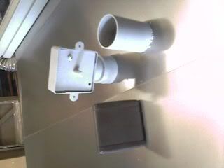
As promised , some pics of the parts you wanted to see ,

Photo-0045.jpg

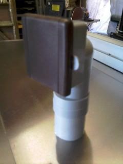
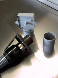
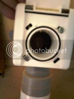
You will need the pipe shown on the (right) which is glued into the holder pipe (centre) wich in turn is glued into the white 50mm ducting pipe

Photo-0044.jpg


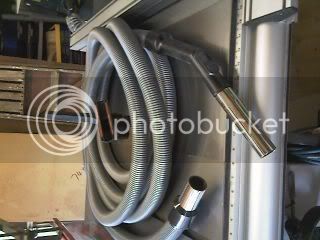
length of hose with some brushes

Photo-0047.jpg


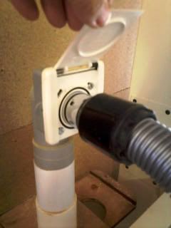
with face plate fitted , it just a tight push in with screw hole if needed

Photo-0046.jpg


face plate fitted to hose connection just a push fit remove face plate to back holder and throw away

Photo-0042.jpg


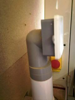
first hoover point fitted into 50mm ducting run

Photo-0041.jpg


in this pic it shows two brass electric 12v point so if you want to connect it up , it will switch on motor of hoover these were design for when you plug in hose to socket .


Photo-0040.jpg


and finally hose plugged in . Hope this of some help to you .
 
head clansman":1etdlw2p said:
Hi all

This is my extraction system started last yr, now just about finished all but for crossing the t.s and dotting the I.s

I wanted to get the best from the system, I didn’t want to spend a heap of money and time fitting all this equipment and then not to be able get the best from it , I first spent a heap of time planning where machines and pipe work would go then slowly a plan came together, first I wanted as much suck as possible so decided to keep pipe runs to a minimum , but with each machine requiring a piped run to the blast chamber at first it was a nightmare I didn’t want all those pipe running over head like a spiders web going off at all different angle and all leading to one blast chamber that you see in so many workshops I decided on one hard pipe feeding all machine , which in turn had to feed the two system that I had decided on, it would also mean a long length of pipe connecting all machine possible running in all direction, this I didn’t like either.

The system incorporates two sizes of pipe work.

50mm 100mm for machinery.

50mm for light dust for hoovering & hand held power tools to cope with MDF dust, hence why I decided to design my own system in the first place.
This bought about my final plan to keep hard pipe work to a bare minimum I decide to split the workshop down the length with machinery on one side and working area on the other this gave me what I wanted the shortest possible hard pipe run of 1.9m including the blast chamber with an air/debris lift of 800mm to the inlet port on the extractor.

In the blast chamber there are three blast gates, the blast chamber is 600mm long from the left black blast gates to the right steel blast gate and there is one 50mm blast gate connected via the 50mm pipe work which is 300mm above the 100mm hard pipe work , plus one 50mm Hoover point .

I also designed it for a minimum lift for all wood debris & dust hence why I didn’t want to go overhead unless I really had to , then only if it was to be lifting dust , so decided to drop as much pipe work to within(600mm) from the floor level . (Minimum lift).

After I got to this stage I could not find a blast gate to fit the 50mm pipe work So I made the blast gates which are a good starting point for this thread.

50MM PVC BLAST GATES

All the 50mm blast gate were made from PVC piping which all came from a company who sells a product called FloPlast here in Weymouth www.floplast.co.uk/ on the trading estate which I’m sure many of you can obtain if you so wish . The blast gates are made from two straight couplings, two short length of pipe, and some off cut of 3/8” plywood left over from when I constructed my workshop, the short lengths of pipe are first glued into one end of both couplings and then the coupling glue into the suction hole in the ply wood which are shown as follows

Photo-0014-1.jpg


Above showing short length of pipe work before gluing

Photo-0127.jpg


Showing suction hole

Photo-0128.jpg


Showing glue bottle and hand grips to be glued

Photo-0129.jpg


The dark areas are wet glue before hand grips were glue

Photo-0130.jpg


This last photo here shows a double hand grip glued , but that was changed , I didn’t like it so I cut off the outer two at either end, all other were then made with only one hand grip either end.

These shots are showing the assemble blast gates from various views.
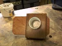
Photo-0123.jpg


Photo-0016-1.jpg


Photo-0015-1.jpg


That just about covers how I went about making these blast gates.

The 100mm blast gates I decided to buy only because I could not find 100mm straight couplers at the time , and partly because of so many other thing going on in my life at that time , but in hindsight I wish I had researched for them a little longer. I used 100mm black plastic ones from Axminster tools, which also can be purchased from just about any good merchants , these get blocked with saw dust in the corners and then the gate won’t close properly so you lose suction, three has broken all replaced with metal blast gates.

50mm & 100mm ducting.

As mentioned, the main hard pipe machine ducting run is a total of 1.9m including the blast chamber of 600mm, so let’s start from the chamber and inlet pipe to the extraction inlet pipe which is 1.4 mm above floor level.

The three photos show the entire length of hard pipe ducting run (left) 1.1m. (Middle) is the blast chamber 600mm width 800mm height. (below) the entire lengths of hard pipe ducting run 1.9m including blast chamber.
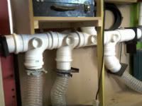
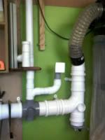
Photo-0028.jpg
Photo-0034.jpg
Photo-0036.jpg


flexible pipework.

From the blast gates these run to all machines independently in 100mm flexi .

Circular saw.

I have the saw mounted to on a turntable so no matter what position I lock the turntable in the flexi remains connected at all times along with the overhead saw guard.
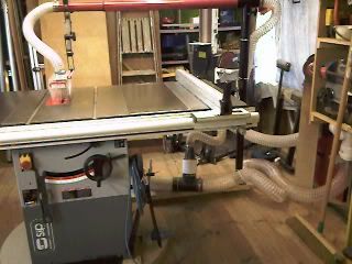
Photo-0023_1.jpg


The first photo shows saw set at 90 degrees across the length of the workshop.
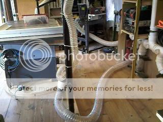
Photo-0018.jpg


This photo shows the saw turned another 90degrees to the right still connected to the flexi pipe.

Planer

This again has a100mm pipe fitted permanently so I can easily change from overhead planing by simple opening the Planer beds and changing to thickness mode the flexi length is 2.5m
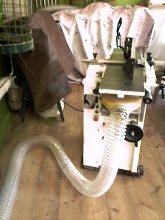
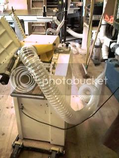
Photo-0032.jpg
Photo-0030.jpg


I have stated that I split the workshop down the length with all machine to one side of the shop, not quite correct with the one exception of the band saw 100mm and 50 mm Hoover point which I had to go overhead with both pipe runs, this pipes can be seen rising vertical in the centre of the right hand photo of the ducting hard pipe.
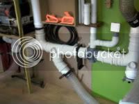
Photo-0036.jpg


50MM DUCTING

I fitted this for the extraction of dust from all power tools i.e.: router sanders and of course a Hoover system so I could get rid of all portable Hoovers and dust bucket plus leads and flexing pipes everywhere, I found this company www.cvcdirect.co.uk and bought three Hoover socket and a seven meter hose which when I plug into two of the sockets I can reach all corners of the shop from both sides of the shop for cleaning dust , the third socket still to be fitted which will be used outside the shop but plumbed through the wall into existing pipe work , so on those warm sunny day when I get to work out side to work I can Hoover all the decks and keep them clean as well .
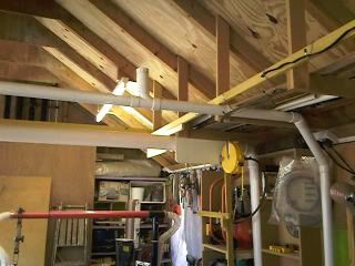
Photo-0023.jpg


Showing pipe runs crossing the shop.

Photo-0026.jpg


Showing Hoover point in lower section of photo where the third Hoover point will go out through the shed wall.

EXTRACTION UNIT DX5000 TWIN MOTORS
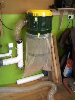
Photo-0037.jpg


shown here with blast chamber, the steel blast gate will be connect to the lathe on the right via the pipes that can be seen in the photo.

Bits and bobs

Still to complete, the placement of a couple more Roding eyes in the 50mm system and the fitting of one more Hoover point.

Conclusion

The only down side of the hole system is the amount of dust that collects under the saw , I stress here not because of lack of suck but the bad SIP design around the saw blade , which is being discussed here at the moment on this very forum , wish they would hurry up and conclude all the design changes they keep coming up with , I’m following that thread with interest.
Photo-0019.jpg


Well guys & girls hope you have enjoyed and it may be of help to someone out there, I know I enjoyed putting it all together, it’s taken a long time and a lot of money but well worth the effort it’s now finally has come together.
Hmm now what do I do now, ah yes complete my infill planes, my tool cabinet, and then ah yes, start my new bench. hc

Boy Martin I wished I had you around here =D> =D> =D> =D> =D> As I said before I have spent a hell of a lot of money on my system, and I am far from happy with it. But hopefully the idea of splitting the system in two and cutting my runs down should see it work better.

What 100mm blast gates did you buy?, because to go along with the spiral pipe work I have the metal ones, and after looking at your 50mm gates I am positive that If I could get 100mm plastic pipe, your design would work a hell of a lot better.

If I am to rip out all of my pipe work and shorten the runs etc, will I be able to make a blast chamber out of metal sprial ducting?

As for the dust collecting under your saw this has been going on for years and SIP's answer in the 12" model was to put a door in so that it is eaier to clean. I am sure that if they sat down and put their brains in gear they could come up with a better design. And if your reading this SIP make sure you sell a kit that owners of older saws can buy and fit.

Many thanks for taking the time to show us your system.

Cheers

Mike
 
hi mike

Now you know what a blast gate is :wink: thanks for the great comments, :D :D .

originally I just used the plastic one's form axminster catalogue which turned out to be useless no disrespect to axminster intended there , there also sold at any tool merchants as well then when these broke i replaced them with 100mm metal ones from axminster, which when fitted to the internal bore of the ducting run is very slack so just wrapped around it duct tape to make up the difference until they fitted snugly.

I Think the 100mm blast gates could be made the same as the 50mm blast gates but could be quite expensive mind, but they would certainly work very effectively and be much better than the plastic or metel one's , you need to buy two straight coupler for each blast gate plus a length of pipe and chop off length to suite, I'm not sure if it's all shown on there web site , take a look and see if not let me know and I'll send you an e mail with a scan of the page, if you need to know any more just let me know. I'll do my best to answer any question for you . hc :lol: :lol: :lol:
 
head clansman":60ejp2bz said:
hi mike

Now you know what a blast gate is :wink: thanks for the great comments, :D :D .

originally I just used the plastic one's form axminster catalogue which turned out to be useless no disrespect to axminster intended there , there also sold at any tool merchants as well then when these broke i replaced them with 100mm metal ones from axminster, which when fitted to the internal bore of the ducting run is very slack so just wrapped around it duct tape to make up the difference until they fitted snugly.

I Think the 100mm blast gates could be made the same as the 50mm blast gates but could be quite expensive mind, but they would certainly work very effectively and be much better than the plastic or metel one's , you need to buy two straight coupler for each blast gate plus a length of pipe and chop off length to suite, I'm not sure if it's all shown on there web site , take a look and see if not let me know and I'll send you an e mail with a scan of the page, if you need to know any more just let me know. I'll do my best to answer any question for you . hc :lol: :lol: :lol:

Hi Martin, your welcome mate.

I don't think I have explained myself properly, because it's the blast chamber (not a blast gate) that I am still unsure about. I cannot get my head around it. I can see the length of pipe work, but what is a blast chamber and what exactly does it do?
If I am to rip out all of my pipe work and shorten the runs etc, will I be able to make a blast chamber out of metal spiral ducting, or would I be better off buying plastic like yours?

Can't you just take a busmans holiday and come up here and do mine :lol: :lol:

Cheers

Mike
 
hi mike

the missus say yes to the busman holiday what part of scotland are you in :?:

this is the blast chamber ,

Photo-0034.jpg


Ok from the left hand side you have the black plastic blast gate on the right there is a metal blast gate pointing downwards and in the middle you have one 50mm blast gate rising upwards and alongside that a square hoover point, ok so far .

now if i close all of the three of the blast gate, because the hoover point is always closed unless i connect the hose there will be one almighty big bang as the plastic bag splits from the suction of the extractor which we don't want to happened :roll: , why has this happened because there is no outlet blast gate open.

If i open only the black plastic blast gate on the left of the chamber it now can suck from any one of the machine connect past that point BUT only if i open it's INDIVIDUAL machines blast gate as well ,in this case i have connected past the left hand chamber gate is a floor pan collection point, the sip saw and the sanding machine all have there own blast gate, it can only suck from that machine as BOTH other blast chamber gates are closed, plus all other gates as well , if i close the last machine i used and NOW close the left hand blast chamber gate. Then if I open the RIGHT hand blast gate I can only suck from what is connected to that blast gate as in THIS CASE in my workshop it will be my lathe, now WHEN I close BOTH left and right hand blastgates and open the 50m blast gate i have that will then shut off the 100mm side of the system and i am now only able to use the 50mm side for hoover and power tools etc .hc :wink: :lol: :lol: hope that helps

PS Mike doing it this way you get to give the full suck to which ever machine you useing at the time your NOT sucking into the lengths of pipe work leading to other machine blast gates as well as the one your operating . the blast chamber controls the direction you want to suck from through which every blast gate you open or shut and through which every size system you choose to use.
 
head clansman":30am7yc2 said:
hi mike

the missus say yes to the busman holiday what part of scotland are you in :?:

this is the blast chamber ,

Photo-0034.jpg


Ok from the left hand side you have the black plastic blast gate on the right there is a metal blast gate pointing downwards and in the middle you have one 50mm blast gate rising upwards and alongside that a square hoover point, ok so far .

now if i close all of the three of the blast gate, because the hoover point is always closed unless i connect the hose there will be one almighty big bang as the plastic bag splits from the suction of the extractor which we don't want to happened :roll: , why has this happened because there is no outlet blast gate open.

If i open only the black plastic blast gate on the left of the chamber it now can suck from any one of the machine connect past that point BUT only if i open it's INDIVIDUAL machines blast gate as well ,in this case i have connected past the left hand chamber gate is a floor pan collection point, the sip saw and the sanding machine all have there own blast gate, it can only suck from that machine as BOTH other blast chamber gates are closed, plus all other gates as well , if i close the last machine i used and NOW close the left hand blast chamber gate. Then if I open the RIGHT hand blast gate I can only suck from what is connected to that blast gate as in THIS CASE in my workshop it will be my lathe, now WHEN I close BOTH left and right hand blastgates and open the 50m blast gate i have that will then shut off the 100mm side of the system and i am now only able to use the 50mm side for hoover and power tools etc .hc :wink: :lol: :lol: hope that helps

PS Mike doing it this way you get to give the full suck to which ever machine you useing at the time your NOT sucking into the lengths of pipe work leading to other machine blast gates as well as the one your operating . the blast chamber controls the direction you want to suck from through which every blast gate you open or shut and through which every size system you choose to use.

Hi Martin, Sorry mate but why are you telling me all this :?: Has someone asked you what a blast chamber is :?: , because I have used one in my system for years :^o :^o and you have got to be a right dummy not to know what it is for :whistle:

Seriously thank you for the explanation. Now that you have told me, it is so obvious that I feel highly embarrassed that I did not see it in the first place, but I was thinking along the lines of a pipe that acted something like a cyclone chamber :roll:

I think the whole problem with my system is the long runs. Even if I am using a machine near to the extractors and have all the blast gates shut, they are still trying to suck from the rest of the ducking running down the shop :roll:

The only trouble is that as I use a sliding table the table saw has to stay in the centre of the workshop. But if I was to set up the blast chamber along one wall, say around 13' of the 26' and split the machines into two 100mm sections, do you think that will work?
As well as the table saw I have permanently set in place a bobbin sander, bandsaw, mortiser, router table, dovetail jig, planer/thicknesser (just used as a thicknesser), a Jet planer, a SCMS, and a big drum sander will be joining these soon. Do you think that I will be able to shorten the runs enough and still have all these in a spilt system?

I am using a Camvac GV386 2200w twin motored extractor who's specs are given in litres 108l/sec (222cfm), an Elektra Beckum SPA 1100 (spec 842 hm3/wy), and a Scheppach HA 2600 (1000 hm3, 1 sec) with a fine filter. I have no idea what these specs mean, or even if they are the figures I should be looking at (can you explain?) But would you sell them all and get one machine to run the lot, just as you have, or could I use them in a spilt system. Would they be powerful enough to use one each side, and the Camvac fitted in somewhere between the two?
As I understand it the Camvac is a hplv machine and the other two are hvlp chip extractors.

Also I note that you have connected your machines to the blast chamber with long length's of flexable pipes. What is the dufference between these and solid or non flexable pipes?

Sorry to high jack your thread mate but you know what you are doing and certainly understand it all.

Cheers

Mike
 
hi mike

don't worry about hi jacking the thread , hmm three extractors and it not working properbly, problems.

mike i think this is one of your main problem move the blast gate to the end of pipe work nearest to where you place the blast chamber so they shut off the length of pipes to what ever machinery is not being used.

I think the whole problem with my system is the long runs. Even if I am using a machine near to the extractors and have all the blast gates shut, they are still trying to suck from the rest of the ducking running down the shop

placing the blast chamber half way down the shop is another good idea, you can split and run off in two or more direction (as i have done) depending on the size of blast chamber (mine 600mm by 600mm with a lift of 800mm) you want just as long as when your using one machine shut all other blast gates on the blast chamber so as i mentioned earlier your only sucking from one machine at a time over the shortest possible length . Remember keep those pipe runs as short as possible draw a sketch of the workshop and move machine about till you can get the shortest possible runs . put some machine on wheels to move about whilst still connected.

the only other thing i would do in your shop as you have more machines than i do ,is the heavier the dust/debris that comes from them the shorter the run lighter dust over the longer runs . see if you can arrange it so it all goes to one extractor . After all your a one man band like mostof us you can only use one machine at a time so why try and suck dust from somewhere if your not using it :?: three extractors hmm not for me but if all else fails. :lol: hc

three extractors hmm not for me but if all else fails.
 
I can't quite get my head round how you're using three extractors on one ducted system, Mike? The reason I'm trying to get my head round it is I'm wondering whether somehow, or other, they are working against each other? Just a thought.

HC - Thanks for the additional pics. I like that idea a lot! I have my TS and Bandsaw on either side of the garage just over half way down. The DX5000 is behind them so I can simply move the pipe from one to the other at the rear. The area where I will be using smaller tools is in front of the TS and Bandsaw so I plan to run a 100mm pipe from behind the TS and Bandsaw reducing down to 50mm and terminating in one of your outlets to connect a smaller hose to. That way I simply plug the extractor in to one of three 100mm ports and I've got the whole shop covered (the lathe is behind the TS and Bandsaw too so I can use it directly over the lathe).
 
hi mike

i missed your comment at the end about the (long) lengths of flexi pipe it used because of the switching to the over and under on the planer which is only 2.5m long and on the saw because it's on a turntable with a length of flexi of 2m all machines stay connected at all times the other to one goes to the sander which is 1.5m and the other one to the lathe which will be about 1.2 maybe . so the longest 100mm run in total length (planer) including every thing up to the inlet port is about 4. 5m, shortest run (lathe) 2.0m . the other to flexi lengths vary between these two measurements. hc
 
head clansman":19x4dcyc said:
hi mike

don't worry about hi jacking the thread , hmm three extractors and it not working properbly, problems.

mike i think this is one of your main problem move the blast gate to the end of pipe work nearest to where you place the blast chamber so they shut off the length of pipes to what ever machinery is not being used.

I think the whole problem with my system is the long runs. Even if I am using a machine near to the extractors and have all the blast gates shut, they are still trying to suck from the rest of the ducking running down the shop

placing the blast chamber half way down the shop is another good idea, you can split and run off in two or more direction (as i have done) depending on the size of blast chamber (mine 600mm by 600mm with a lift of 800mm) you want just as long as when your using one machine shut all other blast gates on the blast chamber so as i mentioned earlier your only sucking from one machine at a time over the shortest possible length . Remember keep those pipe runs as short as possible draw a sketch of the workshop and move machine about till you can get the shortest possible runs . put some machine on wheels to move about whilst still connected.

the only other thing i would do in your shop as you have more machines than i do ,is the heavier the dust/debris that comes from them the shorter the run lighter dust over the longer runs . see if you can arrange it so it all goes to one extractor . After all your a one man band like most of us you can only use one machine at a time so why try and suck dust from somewhere if your not using it :?: three extractors hmm not for me but if all else fails. :lol: hc

three extractors hmm not for me but if all else fails.

Hi Martin,

Yes 3 extractors, they came my way one at a time, and so as I already had them I saw no reason to use them, thinking the more suck the better. How wrong could I be :roll:

Matt wrote;

I can't quite get my head round how you're using three extractors on one ducted system, Mike? The reason I'm trying to get my head round it is I'm wondering whether somehow, or other, they are working against each other? Just a thought.

Hi Matt, Someone else said this, and I think along with too long a length of ducting you have hit the nail on the head.

Can either of you comment on the so called power figures of the above extractors, and what I should be looking for?

Thanks to you both.

Oh by the way Martin tell the Mrs that we live in Fraserburgh :lol:

Cheers

Mike
 
Hello Martin,

Thanks for taking the time to post details and pictures of your impressive dust extraction system. Very informative in deed and much food for thought.

Well done Martin.

All the best, Tony.
 
Martin - thanks for the detailed info on your system...indeed food for thought. I'm intrigued by the wooden blast gates...why are the plastic ones from Axminster NFU? Your wooden ones certainly look easy enough to make.

Which is the best way to mount them, ie is the wooden gate with the hole in it vertical or horizontal? - Rob
 
hi mike

Mike i wish i could tell you what it all means but I'm afraid i cannot it's all double dutch to me, :lol: (no pun intended there to our dutch members) all those figure didn't mean anything to me at all . I read a lot from this forum at the time I think it was Rod (woodbloke) at that time who pointed me in the right direction extraction wise with camvacs twin motors.

I happened to go to yandle a wee while later while i was till mulling things over as you do, they had one ex display unit the DX5000 at a huge discount, After a short demo, I took a chance and bought it.

Can either of you comment on the so called power figures of the above extractors, and what I should be looking for?


Before i started fitting it all I experimented with It , I attached temporary different lengths of pipe , different dia pipes switching from one to the other to see the difference in the power of the suction, this proved invaluable one of the reason why i fitted two size pipes shorter length larger diameter for heavier dust/debris longer length smaller diameter for dust, don't mix the two diameter IMHO keep it so you can switch between both system seperate . hc
 
head clansman":8d99qp35 said:
hi mike

Mike i wish i could tell you what it all means but I'm afraid i cannot it's all double dutch to me, :lol: (no pun intended there to our dutch members) all those figure didn't mean anything to me at all . I read a lot from this forum at the time I think it was Rod (woodbloke) at that time who pointed me in the right direction extraction wise with camvacs twin motors.

I happened to go to yandle a wee while later while i was till mulling things over as you do, they had one ex display unit the DX5000 at a huge discount, After a short demo, I took a chance and bought it.

Can either of you comment on the so called power figures of the above extractors, and what I should be looking for?


Before i started fitting it all I experimented with It , I attached temporary different lengths of pipe , different dia pipes switching from one to the other to see the difference in the power of the suction, this proved invaluable one of the reason why i fitted two size pipes shorter length larger diameter for heavier dust/debris longer length smaller diameter for dust, don't mix the two diameter IMHO keep it so you can switch between both system separate . hc

No problem Martin, If the figures are anything like A/V manufacturers where they give you the maximum power a set of speakers will take (eg a 1000W), when in the real world the figures are more like 300W RMS, then they probably mean nothing anyway.

I think what I am going to do is set up a temporary spilt system and see how each of the extractors preform with the machines and length of ducting, and take it from there. .

Cheers

Mike
 
hi mike

just a thought out of interest post your finding with plenty of pics . hc

ps my dx5000 if your interested had twin 1000w each motor if thats of any help
 

Latest posts

Back
Top