Mitre plane restoration

UKworkshop.co.uk

Help Support UKworkshop.co.uk:

This site may earn a commission from merchant affiliate links, including eBay, Amazon, and others.

richarnold

Established Member
Joined
10 Apr 2012
Messages
419
Reaction score
3
Location
market harborough
While I was at the last David Stanley auction, One of the dealers I know offered me a plane that he had thought I might be interested in . I think I have gained a reputation for taking on old wooden planes that any right minded dealer would consider ready for the scrap heap, and this sorry example certainly fell in to this category. Had it not been such a rare plane I’m sure it would have been broken down for spares. Wooden mtire planes are rare beasts at the best of times, but this example had an unusual feature that made it even more important to rescue. The boxwood mouth closer is usually formed with a slight taper so that when it is driven down into the plane it tightens up due to the wedging action. In this example the insert is parallel and has a brass insert fitted with a cheese headed locking bolt. This engages into a captive steel nut which has been inserted into a mortice formed in the top of the stock. This has been neatly plugged over with a matching piece of beech. The maker of the plane is John Griffiths of Norwich, and apparently there have been two other examples by this maker found with the same feature.


Unfortunately at some time the plane must have stood in a damp location as the sole had suffered from wet rot at some point. It was also worm eaten at the heel of the stock. To add insult to injury, someone had run the sole and the sides over a surfacer!! I decided that the best way to rescue this plane was to graft new sides and base to the body using wood from an old jack plane. I managed to preserve the chamfers from the donor plane for the front end and the top, so it was only the rear that needed re working. The original uncut Sorby iron was badly pitted, but I’m slowly getting it back to a usable condition. All in all I think it was worth saving


Very good Richard. Looks like the invisible menders have been at work.

I can imagine what a state the iron must be in if that's what the damp storage did to the wood ...
 
Marvellous!

I especially like the grafted-on old sides and sole - I've never seen that done before.

If you happen to have a few dozen more pictures and were waiting to be asked -please show us more!
 
Yes please more pictures!

I don't really understand how the inset works or what it does. Could you explain it a bit more?
 
Nice save Rich!

Just how much of the sides did you cut off ?

Pete
 
I have took some more pictures of the repair. As always I’m regretting not taking photos of work in progress. I will try to explain as best I can how I executed the repair. The sides were planed down to the point where the chamfers begin on the top edge. I then planed the base down until it was flat and true. I then took a battered jack plane body and sawed about a ¼” off the base. Then I removed the sides of the jack, leaving the chamfers intact. These were then glued onto the sides of the mitre plane stock, keeping the glue line as close to the edge of the chamfer as possible. The sides were also left protruding from the base by about ¼”. Once they were dry I cut the protrusion back on the inside by about 45 degrees This was achieved with a long paring chisel, and a metal shoulder plane. The piece of wood saved from the sole of the donor plane was then carefully fitted in between the sides. In theory this should have left an invisible joint between the sides and the base, but when everything was cleaned up you can just see the glue joint on the base. The hardest area to finish is the end grain as there is bound to be a visible line to the base and sides. I used to work as a violin, and cello restorer, and a useful tip is when trying to create an invisible glue line is to use what we used to refer to as crack filler. This is actually just a matt cellulose lacquer, or sanding sealer. You can apply it to the joint with a small artists brush. This is done in a few coats until it stops sinking into the crack. Once you have achieved this you can scrape back the excesses with a scalpel blade. This then provides a level surface that any further colouring will not sink into the joint and darken it.
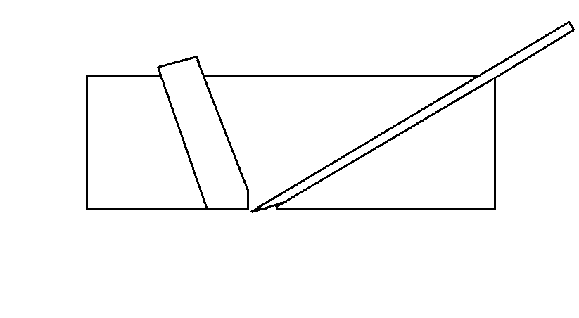
In answer to the question about the mouth insert, the idea is that as the sole of the plane wears down, the boxwood insert can be tapped down to close the mouth up again. This is achieved as the lower edge of the boxwood is bevelled back for a small distance.
Cheers Richard


Corneel":6re8hil0 said:
Yes please more pictures!

I don't really understand how the inset works or what it does. Could you explain it a bit more?

I don't know if Steve Knight's site is still up, bit the planes he made used the same technique, but taken from a Japanese heritage in his case.

BugBear
 
richarnold":iq4a8iwh said:
The original uncut Sorby iron was badly pitted, but I’m slowly getting it back to a usable condition.

As I'm sure you know, but I'll mention just to confirm, I Sorby was the usual brand of blade used in Griffiths planes, which supports the idea that it is the original.

BugBear
 
Wow, thanks a 1000 times! You did a wonderfull job.

So, if I understand it correctly, when the mouth opens, you would tap the insert down, and adjust the small bevel with a file or so, until the mouth gap is correct again? That would mean, the insert is always too thick thoughout the life cycle of the plane?

Somehow I have a hard time to wrap my mind around this. Is it something like this?

 
Corneel -

Not that I have ever had one to play with but it looks like the angle that the mouth - closer is fitted into the plane is all that is needed to maintain the tightness of mouth.

Being Box (usually) it would seem that another function is to keep a hard - wearing, flat area immediately in front of the iron. Which is, as I'm sure you know, bevel up. :)
 
Oops, sorry about the bevel orientation!

I fail to see how the angle of the insert helps to close the mouth, when the insert has parallel sides. Pushing it down doesn't change the mouth.
 
Yes - there is a small bevel at the bottom of the insert as in your drawing and as Richard says above:

"This is achieved as the lower edge of the boxwood is bevelled back for a small distance. "

The angle of the insert pushes the flatter edge toward the iron. It is difficult to visualise with out having one in front of me.
 
Thank you. Then I understood it correctly.

The wooden mitre plane never was a huge succes it seems. Maybe because the low bedding angle gave problems in the wood under the iron?
 
Richard T":u3jvwasb said:
Corneel -

Not that I have ever had one to play with but it looks like the angle that the mouth - closer is fitted into the plane is all that is needed to maintain the tightness of mouth.

Being Box (usually) it would seem that another function is to keep a hard - wearing, flat area immediately in front of the iron. Which is, as I'm sure you know, bevel up. :)

I think most wooden low angle planes are bevel down. It gives a lower EP. In a metal plane, you can go low bedding angle, and bevel up, but wood can't tolerate the super low (e.g. 12 degree) thin bed that results.

BugBear
 
Yes, when I look at this picture, I'd guess a 35 degree angle. That's very low allready for a wooden plane. And 35 degrees is starting to get you troubles with the clearance angle.

001_zps2fd22c5c.jpg


Hmm, copying the adres from the picture doesn't work. I mean, the last picture from Richard's first post.
 
Just to clarify a few points, the angle of the iron is pitched at 25 degrees on this plane which seems to be the most common angle used. My good friend bill carter has been experimenting with making some mitre planes with a 30 degree pitch This is based on a late 19th century mitre plane by Mathieson. All these planes with a box insert to the mouth are always bevel up. Strike block planes have a higher pitch at about 35 degrees and are bevel down. The first mitre plane that I made for myself is pitched at 20 degrees, and so far shows no sign of splitting at the sole. Bill Carter has the theory that a lot of the mitre planes you see that have failed may be due to the beech shrinking at a faster rate than the box across the width of the body. Bill now leaves his inserts loose in the width for this reason. The boxwood insets in most of these planes are slightly wedge shaped in there thickness, so as bill pointed out there is no reason for them to be a tight fit in there width.
I have a mitre plane in my collection by Varvill of York which has failed at the mouth, and if you place a strait edge on the side near the insert there is a definite bulge directly in line with the insert, so bills theory is probably correct . This may be why Mr Grithiths added the bolt to hold the insert into position as it is not a particularly tight fit. It is also parallel in it's thickness with taper at all


richarnold":2fqo6qw8 said:
Just to clarify a few points, the angle of the iron is pitched at 25 degrees on this plane which seems to be the most common angle used. My good friend bill carter has been experimenting with making some mitre planes with a 30 degree pitch This is based on a late 19th century mitre plane by Mathieson. All these planes with a box insert to the mouth are always bevel up. Strike block planes have a higher pitch at about 35 degrees and are bevel down.

I stand corrected, and better informed. Thank you.

BugBear
 
I think you and Bill are right, shrinkage can be seen on lots of wooden planed with cracked cheeks. I have a ones where I had to grind the edges of the iron down as it was tight against the sides, making lateral adjustment impossible.

Pete
 
Thanks for the information Richard. It's a lot like the German Vergatt hobel, allready described in a dictionary in the early 18th century. They were bevel up too, so I should have known.

With a 25 degree bedding you get an effective cutting angle aound 50 to 55 degrees. Hardly ideal for endgrain work. And because a tight mouth isn't really neccessary for endgrain, one wonders why they call this a mitre plane.
 
Back
Top