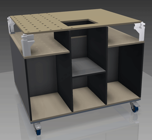
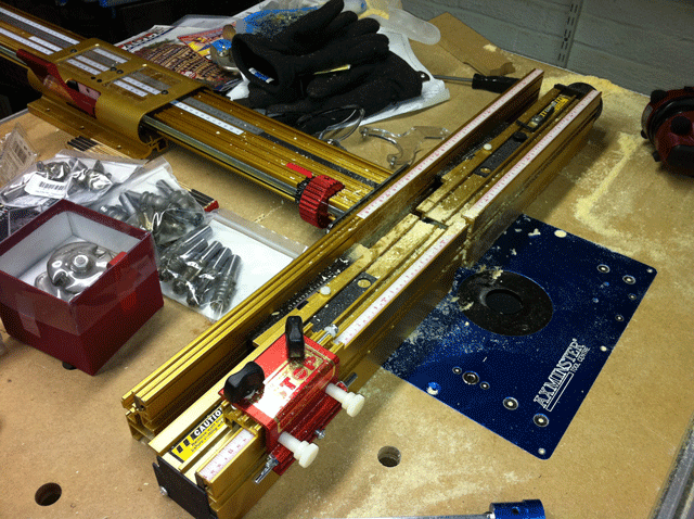
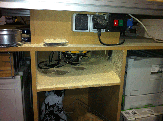
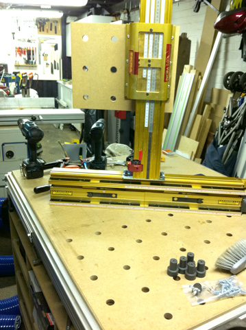
I made my own version of the Festool MFT some time ago, and thought to share how I did the holes, since that is a question I often get.

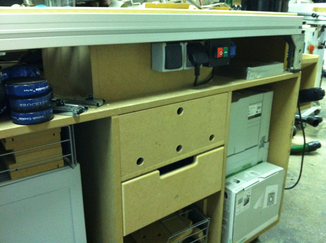
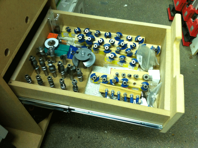
The end result, even though it has been modified with an built in Router table since the picture was taken. But that is for a later thread.

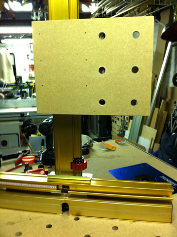
I got the inspiration using "dogs" from one of the Festool forums. The problem many had was how to make the holes parallel and accurate. Some invented great techniques solving the problem, but I wanted a simpler method. So I came up with this, a square with 25 holes accuratly spaced according to the original MFT. I made 2 kind of "dogs", one set for locking the template when routing and one set of "dogs" for normal work.

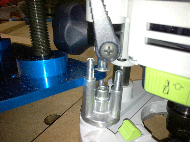
A 30 mm copy ring and a 20mm routerbit was ordered

Ring and routerbit in place, the template is carefully aligned with the corner and edges of the MFT top

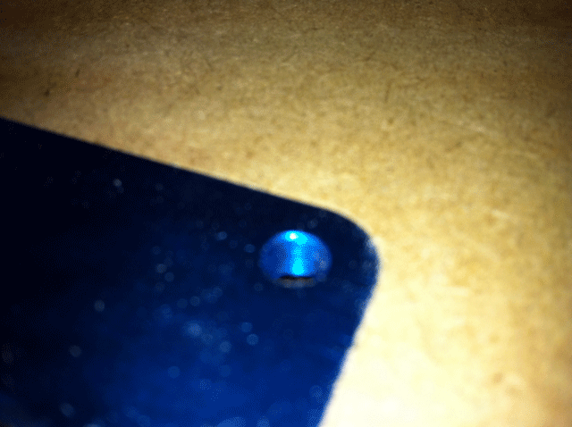
First hole routed, and perhaps now you can see why the first row has a countersunk hole

First locking "dog" in place and flush with the templates top surface.

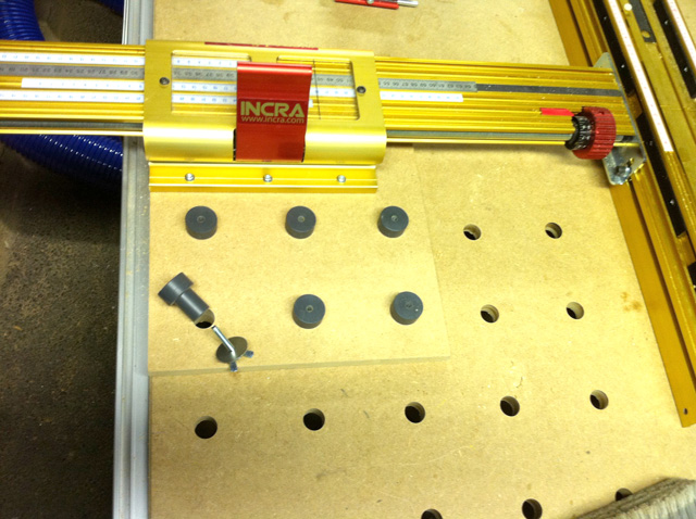
First row finished with the 3 locking "dogs". The template sits rock solid!

All the holes are cut

Now, the locking dogs are removed and the template is moved so that the first row of the template is aligned with the last row that was cut. The locking "dogs" secures the template ones again.

Another angle

Done and finished!
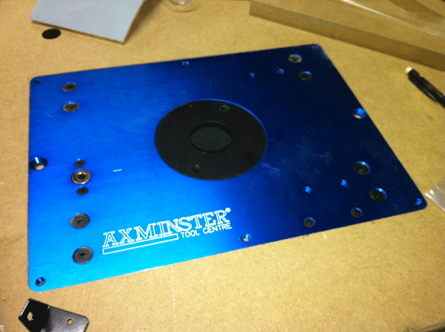
This template can of course be made with as many rows and columns as desired. and I wanted it in acrylic. But the company that laser cut this had this 10mm metal plate laying around so I took that instead!
Take care
/Matt
http://www.solidmind.se

The end result, even though it has been modified with an built in Router table since the picture was taken. But that is for a later thread.

I got the inspiration using "dogs" from one of the Festool forums. The problem many had was how to make the holes parallel and accurate. Some invented great techniques solving the problem, but I wanted a simpler method. So I came up with this, a square with 25 holes accuratly spaced according to the original MFT. I made 2 kind of "dogs", one set for locking the template when routing and one set of "dogs" for normal work.

A 30 mm copy ring and a 20mm routerbit was ordered

Ring and routerbit in place, the template is carefully aligned with the corner and edges of the MFT top

First hole routed, and perhaps now you can see why the first row has a countersunk hole

First locking "dog" in place and flush with the templates top surface.

First row finished with the 3 locking "dogs". The template sits rock solid!

All the holes are cut

Now, the locking dogs are removed and the template is moved so that the first row of the template is aligned with the last row that was cut. The locking "dogs" secures the template ones again.

Another angle

Done and finished!
This template can of course be made with as many rows and columns as desired. and I wanted it in acrylic. But the company that laser cut this had this 10mm metal plate laying around so I took that instead!
Take care
/Matt
http://www.solidmind.se


